Worcester Polytechnic Institute
Digital WPI
Major Qualifying Projects (All Years) Major Qualifying Projects
April 2018
Autonomous Campus Mobility Platform
Dylan Michael RoncatiWorcester Polytechnic Institute Garrison J. Hefter Worcester Polytechnic Institute Md ShamsurRahman Saikat Worcester Polytechnic Institute Mitch Read
Worcester Polytechnic Institute
Follow this and additional works at:https://digitalcommons.wpi.edu/mqp-all
This Unrestricted is brought to you for free and open access by the Major Qualifying Projects at Digital WPI. It has been accepted for inclusion in Major Qualifying Projects (All Years) by an authorized administrator of Digital WPI. For more information, please [email protected].
Repository Citation
Roncati, D. M., Hefter, G. J., Saikat, M. S., & Read, M. (2018).Autonomous Campus Mobility Platform. Retrieved from
Autonomous Campus Mobility Platform
A MAJOR QUALIFYING PROJECT REPORT WORCESTER POLYTECHNIC INSTITUTE
Submitted to Project Advisor: Cagdas Onal, WPI Professor
Submitted by: Garrison Hefter Mitch Read Dylan Roncati
Md Shamsur Rahman Saikat
Date: April 26, 2018
This report represents the work of WPI undergraduate students submitted to the faculty as evidence of completion of a degree requirement. WPI routinely publishes these reports on its website without
editorial or peer review. For more information about the projects program at WPI, please see http://www.wpi.edu/academics/ugradstudies/project-learning.html
1
AUTONOMOUS CAMPUS MOBILITY PLATFORM
Abstract
This Major Qualifying Project (MQP) is based around the development of a robotic vehicle for use in improving mobility. The main objective was to create an autonomous vehicle capable of navigating a person or cargo back and forth from Higgins Laboratory on the
Worcester Polytechnic Institute (WPI) main campus to the Robotics Laboratory located at 85 Prescott Street, approximately 0.6 miles away. An autonomous robot was uniquely designed as a personal mobility platform to navigate its environment using onboard navigation and sensing system.
We considered various levels of autonomy, researched the options for platforms, and established the primary and secondary requirements for our vehicle. Based on the specified requirements and budget we settled on a longboard design for the chassis. The lightweight, compact and portable design makes it ideal for driving on a sidewalk. Battery powered motors along with custom steering assembly and a control system allow for locomotion and navigation through information derived from various interfaces.
AUTONOMOUS CAMPUS MOBILITY PLATFORM
Acknowledgements
The team would like to express many thanks toward our project advisor, Professor Cagdas Onal, for his assistance and guidance throughout this project.
3
AUTONOMOUS CAMPUS MOBILITY PLATFORM
Table of Contents
Abstract 1 Acknowledgements 2 Table of Contents 3 List of Figures 6 1. Introduction 9 2. Background 10 2.1 Levels of Autonomy 102.2 Personal Autonomous Vehicles 12
2.2.1 Powered Wheelchair Bases 12
2.2.2 Scooter Bases 14
2.2.3 Longboard Bases 15
2.2.3 Conclusion 16
2.3 Sensors and Communication Hardware 16
2.4 Motors and Power Sources 18
3. Goal Statement and Objectives 19
4. Task Specifications 20 4.1 Primary Specifications 20 4.2 Secondary Specifications 21 5. Community Interest 22 6. Design Overview 23 7. Mechanical Design 24 7.1 Chassis 24
7.1.1 Longboard Deck Design and Construction 24 7.1.2 Board Design and Removable Handlebar Design 26
7.1.3 Trucks 27
7.1.4 Board and Component Protection Considerations 27
7.1.5 LIDAR Support 29
7.1.6 Longboard Construction 29
7.1.7 Electronic Component Enclosure 31
7.2 Drive System 36
7.2.1 Drivetrain Design and Assembly 36
AUTONOMOUS CAMPUS MOBILITY PLATFORM
7.3 Steering System 41
7.4 Structural Analysis of Steering Assembly 44
7.5 Power Distribution 47
7.6 Thermal Design 48
8. Sensing and Control 50
8.1 Sensors 50
8.1.1 Global Positioning System (GPS) 50
8.1.2 Digital Compass 51
8.1.3 LIDAR 51
8.2 System Architecture 53
8.3 Navigation and Control 53
8.3.1 Program Logic 53
8.3.2 Locomotion and Odometry 55
8.3.4 State estimation using Kalman Filter 57
Prediction Step: 57
Kalman Gain: 58
Update: 58
8.4 Obstacle Avoidance 59
9. Results 60
9.1 Summary of Technical Specifications 60
9.1.1 Primary Specifications 60
9.1.2 Secondary Specifications 62
9.2 Test Results 63
9.2.1 GPS Module 63
9.2.2 Drive Module Test 64
9.2.3 Steering Module Test 64
9.2.4 Simulation Results: 65 Test 1: 65 Test 2: 66 Test 3: 66 Test 4: 68 Test 5: 68 10. Conclusions 69 Bibliography 70 VIDEOS 70
5
AUTONOMOUS CAMPUS MOBILITY PLATFORM
ARTICLES 71
WEBSITES 74
Past MQP Projects 75
Appendices 76
Appendix A - Magnetometer Calibration 76
Appendix B - VESC Tool and Motor Controller Configuration 77 Appendix C - GPS Measurement to Cartesian Coordinates 78
Appendix D - Stress Analysis 79
Appendix E - Future Recommendations 80
AUTONOMOUS CAMPUS MOBILITY PLATFORM
List of Figures
Figure 1: Levels of Vehicle Autonomy (Breznak 2008)... 10
Figure 2: Closed-loop control of autonomous machines can be demonstrated in a flowchart. ... 11
Figure 3: Sensor Components of WPI Semi-Autonomous Wheelchair (Qiao, 2016) ... 13
Figure 4: MIT Autonomous Wheelchair Demonstration (Teller) ... 13
Figure 5: SCEWO Wheelchair with Segway Base (SCEWO, 2017) ... 14
Figure 6: MIT Autonomous Scooter (Hardesty, 2016) ... 14
Figure 7: XTND Board (XTND, 2017) ... 15
Figure 8: Longboard deck shapes left to right: Free rider, Cruiser, Racer, Dancer, ... 24
Figure 9: Preliminary Board SOLIDWORKS Design ... 26
Figure 10: Preliminary Handle Locking design ... 26
Figure 11: Acrylic LIDAR Support... 29
Figure 12: Rough cutting on the bandsaw. ... 29
Figure 13: a) Left: Verifying against pattern b) Right: Trimming with router ... 30
Figure 14: Finish on spindle sander ... 30
Figure 15: Finished longboard deck ... 30
Figure 16: Boring hole in side of vacuum forming machine ... 31
Figure 17: a) Left: Drilling of holes and b) Right: clamping during construction of vacuum ... 32
Figure 18: a) Left: Construction of vacuum forming machine and b) Right: Final ... 32
Figure 19: a) Left: 3D mold and b) Right: Frame view during process of oven... 33
Figure 20: a) Left: Vacuum forming machine and b) Right: Attached vacuum ... 34
Figure 21: Final cover ... 34
Figure 22: a) Left: Construction of cover base and b) Right: Final assembled cover ... 35
Figure 23: Basic Drivetrain setup without belt ... 37
Figure 24: Wheel clamped for drilling bolt holes. ... 37
Figure 25: Assembled drivetrain on rear truck ... 38
Figure 26: Motor mount SOLIDWORKS model... 38
Figure 27: Faces used for fixed geometry constraint ... 39
Figure 28: Modeling of the moment load created by motor weight ... 40
7
AUTONOMOUS CAMPUS MOBILITY PLATFORM
Figure 30: Stress distribution on the mount ... 41
Figure 31: Preliminary model for steering ... 41
Figure 32: Bosch seat motor servo for steering ... 42
Figure 33: Steering assembly view ... 42
Figure 34: Adaptor 2... 43
Figure 35: Base plate hole dimension analysis ... 45
Figure 36: Electrical Diagram ... 47
Figure 37: Temperature sensor points are marked with green squares. ... 48
Figure 38: Enclosure Temperature Readings without Fan ... 49
Figure 39: Enclosure Temperature readings with Fan ... 49
Figure 40: BerryGPS-IMU v2 (left), XV-11 LIDAR (right) ... 50
Figure 41: Raw GPS data format ... 50
Figure 42: XV-11 LIDAR Controller ... 52
Figure 43: LIDAR Calibration Visual ... 52
Figure 44: System Architecture showing communication between processors, sensors and ESCs. .... 53
Figure 45: Flowchart summarizing navigation logic... 55
Figure 46: Kinematic bicycle model for the longboard adopted from Polack et al., 2017. ... 56
Figure 47: Obstacle detection range using LIDAR. ... 59
Figure 48: Google maps view of path chosen for test on WPI track. ... 63
Figure 49: GPS position (orange) given by our sensor along the waypoints from google maps (blue)63 Figure 50: Estimated position using different scale factors compared against measured position. ... 64
Figure 51: Simulated autonomous navigation without obstacle detection. ... 65
Figure 52: Control parameters leading to divergence from trajectory. ... 66
Figure 53: Obstacle avoidance with minimum steering angle. ... 67
Figure 54: Close up view of obstacle avoidance. ... 67
Figure 55: Close up view showing overshoot during steering corrections. ... 68
Figure 56: Simulated proportional control resulting in smooth trajectory. ... 68
Figure 57: Magnetometer readings from rotating the sensor, before and after calibration. ... 76
Figure 58: User interface of the application used to configure the drive motor. ... 77
Figure 59: Rear Truck Support... 79
Figure 60: Drive Truck Support ... 79
AUTONOMOUS CAMPUS MOBILITY PLATFORM
Figure 62: Bottom Bearing Support ... 79 Figure 63: Top Bearing Support ... 79
9
AUTONOMOUS CAMPUS MOBILITY PLATFORM
1. Introduction
This Major Qualifying Project was done to create an autonomous mobility platform to transfer a person from the main WPI campus to the robotics building at 85 Prescott Street. The goal of this platform is to provide a light, effective, and autonomous solution to transportation on and around campus. While there are existing solutions serving similar goals, our design and implementation varies from these to provide benefits in that it offers the possibility of travel to individuals with compromised mobility and those without mobility issues, which is not offered in any other research space currently.
After careful consideration and discussion in the early stages of this project, the team chose to design and build a solid wood longboard chassis as the basis for this mobility platform. This base was chosen for its compact size and portability in contrast to the cumbersome existing wheelchair and scooter technologies. The chassis includes a battery-powered motor for
locomotion, a handle for steering, control system, and various sensors for environmental
orientation. The robot is designed to navigate its environment using GPS navigation system, and LIDAR. Navigational decisions are made by the robotic vehicle via information derived through various interfaces.
This platform completes the following requirements to demonstrate fulfillment of requirements differing from any existing system.
● The platform is light and compact enough for an adult to lift and carry
● The platform is able to autonomously navigate a person or cargo back and forth from a specified location on campus and back.
AUTONOMOUS CAMPUS MOBILITY PLATFORM
2. Background
Autonomous systems have been used at various scales for transportation for decades. They are used in aviation, weaponry, automobiles, industrial robotics, among others. The goal of this project inherently defines the scope as such that it is most relevant to technologies used in autonomous cars and personal mobility devices.
2.1 Levels of Autonomy
The capabilities of autonomous systems generally vary widely upon the application. According to the Society of Automotive Engineers (SAE) standard, vehicular automation can be classified into six levels, Level 0 - Level 5. The classification is primarily based on level of human intervention required to accomplish a task. The following visual (Figure 1) from a report published by the International Transport Forum summarizes these different levels of autonomy:
11
AUTONOMOUS CAMPUS MOBILITY PLATFORM
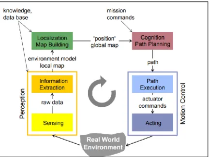
Recent advances in self-driving vehicle technologies have enabled the achievement of Level 4: High Automation, albeit existing systems are still under testing and development. Equipping a system with Level-4 automation requires it to be data driven. Information is required to be constantly fed into the system and processed by complex algorithms in order to monitor changes continuously and perceive the dynamic environment (Autonomous Intelligent Vehicles, 2011). Figure 2 shows a control scheme for a generic autonomous mobile robot.
Figure 2: Closed-loop control of autonomous machines can be demonstrated in a flowchart.
The chain of actions shown in this figure involves four main processes: localization, path-planning, locomotion and obstacle avoidance. In order to move from point A to point B, the robot needs to know its current position and destination, how to navigate in physical space to get to the desired position without hitting obstacles, and how to mechanically drive itself
(Autonomous Intelligent Systems, 2011). Each of these processes require fusion of information from all of the subsystems. Even though the intelligent systems in autonomous outdoor vehicles are based on similar technologies to indoor mobile robots, it is significantly more challenging to integrate them in a vehicular platform. Developing a reliable intelligent transport system requires practical resources and innovation, supply of which can be justified by fulfilling a big market segment. Thus, currently we have large automotive companies competing for self-driving cars and small scale commercial products or research projects for personal mobility platforms as an assistive device. Consequently, there lies an empty niche that can potentially bridge autonomous mobility and personal transport.
AUTONOMOUS CAMPUS MOBILITY PLATFORM
2.2 Personal Autonomous Vehicles
In this section, we examine and discuss the most current existing personal autonomous vehicle technology. Our research into these vehicles allows us to determine the attributes to consider in the development of this project. We explored varying chassis styles, sensor technologies, motors, power sources and sensors.
Determining which chassis to use for our vehicle began with an exploration of existing personal autonomous vehicles with a view toward creating a more lightweight and portable base. We discovered that most personal mobility devices have historically built on either wheelchair or scooter bases where the rider must travel in a seated position. More recently, however, the
development of powered longboards has opened the possibility for upright autonomous mobility.
2.2.1 Powered Wheelchair Bases
There has been considerable research and development into adapting a standard
powered wheelchair base as an autonomous mobility platform. We focused our research on the most recent projects and considered their individual attributes for possible incorporation in our project design.
In 2016, a semi-autonomous wheelchair was developed at Worcester Polytechnic Institute (WPI) using an existing powered wheelchair base. The project was designed to accommodate individuals with compromised physical mobility who are unable to use a traditional joystick controller. In order to accommodate individuals with such a degree of immobility, it is necessary to provide a seated position for travel. This platform included a laser rangefinder (LIDAR) to generate a map of the surrounding environment and localize the vehicle, and ultrasonic and infrared range sensors were used for obstacle and collision avoidance (Qiao, 2016).
13
AUTONOMOUS CAMPUS MOBILITY PLATFORM
Figure 3: Sensor Components of WPI Semi-Autonomous Wheelchair (Qiao, 2016)
Similar autonomous mobility technology on a powered wheelchair base is under
development at Massachusetts Institute of Technology (MIT). This technology is appropriate for people who have lost mobility due to brain injury or the loss of limbs, but who retain speech (MIT 2017). Project objectives center around the implementation of a voice-operated device that learns its environment and is capable of detecting objects and avoiding collisions. This required a speech interface to interpret commands, a wireless location device and motor-control software to direct the wheelchair’s motion (MIT, 2017). This robotic wheelchair is capable of learning the layout of its environment and moving to any previously visited location (MIT, 2017).
AUTONOMOUS CAMPUS MOBILITY PLATFORM
Using a Segway wheelbase, the SCEWO autonomous wheelchair has as project
objectives self-balancing technology to enable it to rotate in place and the ability to climb steps. The design is functional and allows for many adjustments in the seating position but does not allow travel in an upright position.
Figure 5: SCEWO Wheelchair with Segway Base (SCEWO, 2017)
2.2.2 Scooter Bases
Recognizing the limitations of the powered wheelchair as a base, particularly for outdoor road travel, research at MIT has centered on the creation of a door-to-curb-to-highway
autonomous transportation system for the mobility impaired. Rather than the two wheeled power chair base, the chassis is a three-wheeled powered scooter that provides more flexibility and better handling. The system includes several layers of software including low-level control algorithms that enable a vehicle to respond immediately to changes in its environment, such as a pedestrian darting across its path (MIT Scooter). In addition, route-planning algorithms,
localization algorithms and map-building algorithms orient the vehicle to its environment and enable efficient navigation (MIT Scooter). A scheduling algorithm is designed to allocate fleet resources and an online booking system that allows users to schedule rides (MIT Scooter).
15
AUTONOMOUS CAMPUS MOBILITY PLATFORM
2.2.3 Longboard Bases
Powered skateboards and longboards are increasingly popular as a lightweight and portable mode of transportation. Currently, there exist some concept models and startup products that integrate smart technologies with a skateboard or longboard base. For instance, Audi has recently unveiled its autonomous longboard, which is made of aluminum and carbon fiber and can be used in one of three modes. It can be mounted and ridden in a standing position as normal longboard, used as a scooter by deploying the integrated handlebar, or put in a cargo mode where it can be loaded with cargo and follow its user autonomously by tracking a phone or smartwatch (Ziegler, 2016). Audi’s board goes over seven miles on each charge and can travel at speeds up to 18 miles per hour (Ziegler, 2016).
Other longboard designs include Marbel 2.0 and the XTND, both commercial products fundraising on Kickstarter. The Marbel 2.0, already available in the market, was developed by a relatively new e-board brand Marbel based in Tampa, Florida. Their main feature is a
downloadable mobile application that acquires data from every ride to allow the rider to
customize the experience by fine tuning various parameters such as acceleration, speed, braking. The XTND, however, raises the bar significantly higher. With the first release slated for January 2018, the XTND board designed by a Czech startup is reportedly the first of its kind to integrate Artificial Intelligence (AI). In addition to similar capabilities of the Marbel 2.0 in terms of ride customization, this board can also fine tune its own parameters in an intelligent way to assist the rider to learn, as well as offering a smooth ride. Among many other features, the XTND offers route optimization based on previous ride data; has step recognition to sense presence of a rider; anti-collision/fall off system to minimize rapid speed change or vibrations at high speed; and automatic sleep mode to conserve battery.
AUTONOMOUS CAMPUS MOBILITY PLATFORM
2.2.3 Conclusion
While both the autonomous wheelchair and scooter offer the possibility of travel to those with compromised mobility, such bases do not allow for travel in an upright position nor are they an appropriate means of travel for those who do not have mobility issues. Our project aims to meet the needs of both.
There are many individuals with other mobility issues that do not require the use of a wheelchair, autonomous vehicles that require the user to be seated unnecessarily confine and restrict the movement of those who are capable of standing. The presumption that everyone with a mobility issue needs to be seated in order to travel autonomously is unwarranted. There are many types of mobility impairments that may require a mobility aid but do not necessarily preclude the individual from remaining in a standing position. Such impairments may include blindness or visual impairment, heart conditions, respiratory disorders, hearing or other sensory impairments. While individuals with these issues may need assistance with transfers and ambulation, they may not need to be restricted to a seated position to receive it.
Additionally, our project brings autonomous transportation to people who are not disabled but who simply need or prefer a lift to their destination. The ability to travel at speeds faster than and without the effort required for walking is appealing to many.
While there are many electric and powered longboards, our project is distinct in that it provides the ability for both abled and disabled riders to travel autonomously.
2.3 Sensors and Communication Hardware
Autonomous vehicles detect their surroundings primarily using RADAR, LIDAR, GPS, odometry, and camera-enabled computer vision. All the sensory data from the preceding sources is then analyzed by the control system. We researched and investigated various
detection systems to determine which were best suited to the safe navigation of our vehicle. Each system has different attributes, not all of which are relevant to our goals.
Many autonomous vehicles employ forward RADAR for navigation. Forward RADAR involves reflected microwaves used to identify the location and speed, but not always the type, of nearby objects. Radio waves are sent out and bounced off objects. A major benefit of RADAR is the ability to detect objects at great distance. It allows the vehicle to see up to 100 meters away in dark, rain, snow or vision impaired circumstances. While this is an important
17
AUTONOMOUS CAMPUS MOBILITY PLATFORM
consideration for night mobility and all types of weather, RADAR cannot differentiate between objects.
Another popular detection system involves the use of LIDAR, essentially the word laser
and RADAR combined. LIDAR works by sending out light pulses and reflecting them off objects. The distance of an object is then measured by detecting its return signal. LIDAR works well in the dark and offers continuous scanning to provide 3D omni-directional view of
surroundings.
The ability to map surroundings is also critical to autonomous vehicles. Once a local map is updated, software processes this information, plots a path and sends instructions to the
“actuators” on the vehicle which control acceleration, braking and steering (Self Driving, 2017). Hard-coded rules, obstacle avoidance algorithms, predictive modeling and “smart” object
discrimination which determines the difference between a person and an object and help the software follow a desired path and navigate obstacles (Self Driving, 2017). There are two possibilities for mapping: (1) an intensive process of manually capturing a detailed map of the vehicle’s surroundings and programing the vehicle. (2) by teaching the vehicle to learn its environment in much the same way as a person would whereby the vehicle is taken around once on a guided tour, with important places identified along the way using GPS receivers (MIT, 2017). Indoor mapping, however, cannot rely on GPS but may be able to achieve using Wifi signals, with wide-field cameras and laser rangefinders, coupled to computer systems that can construct and localize within an internal map of the environment as they move around (MIT, 2017). GPScombined with high-precision mapping is used to determine a vehicle’s position on the road.
Forward-facing camerauses image-processing software to detect lane stripes, signs, and other objects (Gates, 2016). Cameras take images that are interpreted by computer. This method of detection is limited to interpreting only what the camera can see. Depending on the type of camera and its position on the vehicle, the camera may only be capable of detecting a small portion of the environment. In addition, it relies on the installation and integration of lane stripes and other objects into the surrounding area to facilitate orientation of vehicle.
Autonomous vehicles use computer vision to convert visual images derived from their detection systems into descriptions to interface with other processes and elicit appropriate actions by a machine such as braking or turning to avoid an object (Stephens, 2016). A multidomain
AUTONOMOUS CAMPUS MOBILITY PLATFORM
controller on board the vehicle manages input from mapping and navigation data from the above detection systems to form navigational decisions.
2.4 Motors and Power Sources
Options for power sources for electric longboards are typically either single or dual drives. Each offers benefits worthy of consideration.
Single drive longboards involve one motor, one mount and one Vedder Electronic Speed Controller (VESC). Having one of each component saves space on the board and keeps the board light. A single drive is more economical than having two of each component.
Importantly, a single drive long board can achieve the same speed as a dual drive. However, acceleration is considerably slower and braking and turning are less efficient with only one motor.
Dual drive longboards are more expensive since there are two motors, two mounts. However, there are many benefits to having dual drives. They have the benefit of reducing the stress on each drive system. In a dual drive, each drive shares the amperes so one motor is not doing all of the work. This translates to motors that run cooler, more efficient braking and faster acceleration. In addition, dual drives work better in off road and harsh weather conditions like snow and heavy rain as they provide better traction.
There were several considerations regarding the drive and selection of appropriate power sources, not the least of which was cost. Overall, while speed is the same whether using single or dual motors, the dual motors provide better acceleration and better braking. Clearly, having dual motors is optimal.
In determining whether to use a single or dual drive on this project, however, cost was a driving factor. A single drive does mean inefficient turning, slower acceleration and less
efficient braking. However, with only one motor, one mount and one VESC, the cost is half that of a dual drive. While our vehicle would likely benefit greatly from dual drives, the cost of having to purchase two of everything would have been prohibitive given our restricted budget for this project.
One more motor or actuator is required to steer the board. While steering can be handled in a number of ways, mounting a sprocket to the truck is very simple. The sprocket can be turned with chain back to the motor or actuator.
19
AUTONOMOUS CAMPUS MOBILITY PLATFORM
3. Goal Statement and Objectives
This project aims to find a means of transporting a person or cargo autonomously from one point to another. Our prototype involves the design and creation of a chassis, drivetrain, sensing and control system for a new autonomous vehicle capable of transporting a person from Higgins Laboratory to 85 Prescott and back.
To achieve our overarching aim, the objectives of the project are defined as follows: 1. To produce a robotic mobility vehicle
2. To design and build a powered chassis
3. To design and build a sensor system allowing the robot to navigate efficiently 4. To develop a control system to analyze data from sensors about the
AUTONOMOUS CAMPUS MOBILITY PLATFORM
4. Task Specifications
This project development was based on two main categories of considerations from which individual attributes were developed.
4.1 Primary Specifications
The primary considerations for the project included physical and mechanical attributes, power and performance requirements and parameters for sensing and autonomy.
In terms of physical and mechanical attributes, we have the following specifications encoded in “Task Spec - Primary - Number” format (TSPXX):
• TSP01- The platform must support and carry 200lbs of load, either cargo or a rider.
• TSP02- The platform must be portable with a total mass of less than 10 kg.
• TSP03- The platform must have a safety feature that assists rider to remain on the platform such as a handle, foot straps, or other means of securing the rider or load.
• TSP04- The platform must have a top speed of 10 mph or below.
• TSP05- The platform must be capable of making multiple trips back and forth from Higgins Labs to 85 Prescott Street on one full charge.
• TSP06- The platform must be able to reach full charge in less than 5 hours.
• TSP07- The platform must be able to locate itself outdoors (using global positioning system (GPS)).
• TSP08- The platform must be able to map its environment at a suitable range for obstacle detection, and minimum stopping distance (which will be determined based on features of design components).
• TSP09- The platform must have a load detection system to sense when a rider or load above a weight of 50lbs is present.
• TSP10- The platform must not exceed the measurements of 12 inches wide, 38 inches long, and 8 inches high.
21
AUTONOMOUS CAMPUS MOBILITY PLATFORM
4.2 Secondary Specifications
Additional mechanical attributes that may be taken into account include ergonomic design elements to minimize discomfort for the rider. In terms of these attributes, we have the following secondary considerations encoded in “Task Spec - Secondary - Number” format (TSSXX):
● TSS01- The platform should be waterproof for outdoor use ● TSS02- The platform should have a commute mode ● TSS03- The platform should have a sport mode
● TSS04- The platform should be able to reach full charge in less than 3 hours
● TSS05- The platform should make independent decisions without user intervention ● TSS06- The platform should be capable of adjusting torque according to terrain.
AUTONOMOUS CAMPUS MOBILITY PLATFORM
5. Community Interest
WPI has a total student population of approximately 6,300 comprised of approximately 4,200 undergraduate and 2,100 graduate students. The number of employees including
professors, administrative and other staff is in the hundreds.
To calculate the proportion of students at WPI who could benefit from a robotic campus mobility platform, we conducted a survey to determine the need or desire for an autonomous mobility platform. There were 400 responses were generated and analyzed to determine the results.
The overwhelming majority of responders, 96%, were students with the remaining 4% made up of faculty and university administration. Of the population, 20% indicated that they had mobility issues that affected their ability to navigate on campus. The majority spend between five and ten minutes walking between campus buildings every day, including trips between the main campus and off campus buildings.
The overall results of the survey were positive for interest. Of the surveyed individuals, 70% were interested in using an autonomous platform to get around campus. Of those, 69% indicated that they were likely to use our particular powered longboard campus mobility platform.
The development and applicability of the mobility platform envisioned by this project is not limited to use on the WPI campus. Such technology can have applications in other domains, including commercial development in the same manner as other autonomous transportation technology including personal vehicles, trains, aircraft and undersea vehicles.
23
AUTONOMOUS CAMPUS MOBILITY PLATFORM
6. Design Overview
After careful consideration of the possible chassis options for this project, we narrowed down our selection to a longboard deck. It offers the most universal use and appeal to those needing assistive mobility devices who are not confined to wheelchairs as well as use by those who are completely able bodied.
In order to simplify the overall design process, the platform has been divided into 5
subsystems according to functionality. The subsystems/subassemblies are tabulated as follows:
Chassis Drivetrain Power
distribution
Steering Sensing/Control Unit
Deck Motor 6S2P LiPo Battery Seat motor Raspberry Pi 3 Handle Motor pulley 3V LiPo for
LIDAR
Sprocket Arduino Uno
Trucks Wheel
pulley
Belt/Chain Teensy 2.0
Motor mount Drive Belt Thrust
bearing
LIDAR
Acrylic Support
Wheels Adapter GPS
AUTONOMOUS CAMPUS MOBILITY PLATFORM
7. Mechanical Design
7.1 Chassis
Preliminary design of the structure of the longboard chassis involved research and consideration of various deck designs and multiple considerations for construction, including choice of materials. The design of the handle was conceived to allow it for stability for users in need of extra stability, but with the flexibility of a fold down storage position for those who do not. Trucks and motor mount selections were made with consideration for the overall design and specifications of the longboard deck, drivetrain, power and sensing units.
7.1.1 Longboard Deck Design and Construction
The first step in design conception of the deck involved consideration of six basic deck shapes typically seen in powered longboard construction: cruiser, carver, slider, free rider, racer, and dancer.
Figure 8: Longboard deck shapes left to right: Free rider, Cruiser, Racer, Dancer,
Each of these deck shapes offers a different ride experience and maneuverability. For our purposes, we chose a modified version of the free rider. This design works well on hills and is ideal for speed. The wheel cutouts allow for maximum handling and turning.
Calculating the space needed for the fold-down handle, a single drive, battery and sensing control units, we settled on deck dimensions of a length of 30 inches (76.2 cm) and a width of 9 inches (22.86 cm) at the widest area of the board and a thickness of 0.625 inches (1.59 cm).
25
AUTONOMOUS CAMPUS MOBILITY PLATFORM
Our next consideration involved choosing the materials to build the deck. The choices included Carbon Fiber, Baltic birch and Maple plywood, Bamboo, and Maple. Each material offered a different combination of benefits and inconveniences.
Carbon fiber offers the most ideal attributes for this project. It is lightweight, durable, stable and can be customized to cover the electronic components. This would be extremely beneficial to protect these components from the negative effects of rain and snow. Unfortunately, this material is extremely expensive and given the budgetary considerations of this project, it was not feasible to use it to construct the deck.
Moving forward, we analyzed the characteristics of the remaining materials before making our final selection. Plywood, while cheap and strong is prone to splintering and is very stiff, which may present difficulties in ease of maneuverability. Bamboo is extremely light, which is an asset in keeping the weight of the board under 10 kg, however it is very brittle, cracks easily and is rather expensive. We concluded that construction a deck out of stacked maple allows for easy customization and offers the rigidity we were looking for at a moderate price.
Rather than making a deck from one solid piece of wood, the deck was constructed by layering the wood in a cross-grain pattern to create a strong board that would be highly resistant to warping or splitting, two of the main disadvantages of natural wood. This project achieved construction of the longboard deck using nine layers of pressed maple veneer, laminated together using modern wood glue and clamping techniques.
AUTONOMOUS CAMPUS MOBILITY PLATFORM
7.1.2 Board Design and Removable Handlebar Design
Figure 9: Preliminary Board SOLIDWORKS Design
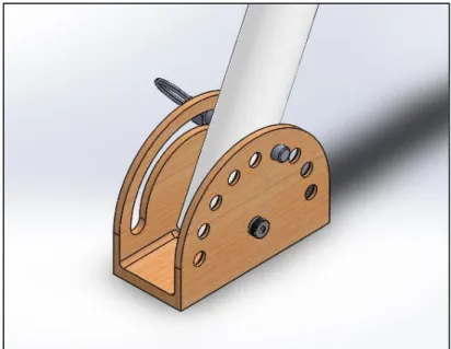
According to our third technical specification (TSP03) the platform must have safety features to assist the rider. One of the safety features we designed was an adjustable handlebar. The handlebar has a max extension of 40.0 in with a minimum collapsed distance of 26.0 in. The 14 in adjustable height allows riders of various heights to hold the handlebar at a position which is most comfortable for them.
Figure 10: Preliminary Handle Locking design
The base for the handlebar is designed so that the handlebar can adjusted to different angles. By pulling the pin and supporting the shaft, the rider can adjust the angle of the handlebar to a comfortable position when riding. The handlebar also has the capability to collapse and lay parallel to the platform for easy storage.
27
AUTONOMOUS CAMPUS MOBILITY PLATFORM
We decided that the most effective way to build the handlebar would be buy the handle and support pieces and to build the base plate. We were able to find precut PVC to dimensions we needed as well as the pull pin we needed on McMaster Carr. We decided to make the base plate out of the maple we used to build the deck. Maple was chosen as it is easy to machine and is strong enough to support the rider and handlebar. This initial design was ultimately not implemented, due to concerns for its appropriateness for a disabled rider.
7.1.3 Trucks
After researching different options, we found that the best way to mount the wheels and steering is using existing longboard trucks that we can purchase, then modify them according to our design. The front truck will need minor modifications to handle steering and the rear truck will need some minor modifications to handle power input to the rear wheels. We have selected a truck set that we have found is the best for our application.
7.1.4 Board and Component Protection Considerations
Electronic components need to be protected from impact and from wet weather. To best achieve this protection, components benefit from dual protection. The first layer of protection usually involves treating the components with a conformal coating. While there are several spray coatings on the market, they are extremely expensive and beyond the budget of this project. For this reason, we decided to not treat our components. Instead, we opted for protection for the electronic components by a protective hard case cover.
The basic considerations for a hard case to protect our electronic components include durability, weight, impermeability, ground clearance and price. There are several such enclosures available for purchase that fit many of our requirements.
We investigated the available designs and concluded that none actually would work perfectly with our specific placement of electronic components on the board. Additionally, after consideration of our budget, we realized that buying a premade enclosure would be prohibitively expensive and not necessarily offer us the characteristics we require in terms of weight and ground clearance.
Instead, we considered three primary ways of creating our own enclosure: 3D printing (ABS or Nylon), repurposing of existing products, and vacuum forming thermoplastic. There are many positive aspects to 3D printing including custom fit, lightweight and easy of creation.
AUTONOMOUS CAMPUS MOBILITY PLATFORM
Depending on the materials used, this type of enclosure has variable durability for our application. We experimented with a basic design in the initial stages of consideration to determine exactly what would be needed.
However, we quickly concluded that the time spent to create the design for 3D printing would likely change throughout the project each time we made adjustments to the placement of our electronic components. In addition, we considered that 3D printing can be time consuming and we may have to print out several prototypes along the way before getting the proper fit. Furthermore, in the event that an enclosure breaks, it would potentially leave our components unprotected and cause delays in testing while we wait for a replacement.
In the interest of budget and time, we briefly considered repurposing materials such as used plastic plant trays and old baking tins as covers for our electronic components. Both are lightweight and waterproof with the plastic being less durable. Neither was particularly pleasing aesthetically, nor did they provide the custom protection we prefer for our components.
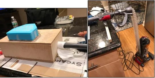
Vacuum formed enclosures provide a custom fit, are lightweight and durable and waterproof. To produce such an enclosure is considerably more work intensive than 3D printing. A vacuum former machine and a mold of the electronic components have to be hand created in advance. The machine consists of a hollow box with a suction port and a grid of holes.
Inexpensive thermoplastic ABS or polycarbonate sheets are heated close to their melting point and then placed on the machine over a mold of the components. Air is vacuum pulled out of the box with a wet dry vacuum and the plastic sheets harden over the mold. This yields an
absolutely custom enclosure.
After careful consideration, we determined that the vacuum forming machine was best suited to our purposes and needs. While initially quite labor intensive, once the vacuum forming machine and mold were and constructed, we could use them to make as many enclosures as we wanted, allowing us to quickly experiment with different designs along the way without losing time.
29
AUTONOMOUS CAMPUS MOBILITY PLATFORM
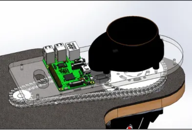
7.1.5 LIDAR Support
On the front of the board we designed, and laser cut an acrylic support to hold the
LIDAR, Arduino and Teensy as well as protect the sprockets and chain from being stepped on by the rider.
Figure 11: Acrylic LIDAR Support
7.1.6 Longboard Construction
Nine thin sheets of maple veneer were coated with standard polyvinyl acetate wood epoxy and then stacked and put into a press to set. To get the strongest bond, the glue was allowed to dry completely for several days before attempting the shaping of the board.
AUTONOMOUS CAMPUS MOBILITY PLATFORM
A pattern for the board was made based on the design specifications. The pattern was transferred by tracing onto the blank deck. The board was rough shaped first on a table saw to cut down on the length. From there, the ends of the board were shaped on a bandsaw. Because of the curves in the design, this took several passes, each time removing a bit to avoid splitting the deck or overcutting the rounded areas.
Figure 13: a) Left: Verifying against pattern b) Right: Trimming with router
Once the shape of the board closely matched the pattern, we used a router all around the perimeter of the board to trim off and refine the shape.
Figure 14: Finish on spindle sander
31
AUTONOMOUS CAMPUS MOBILITY PLATFORM
7.1.7 Electronic Component Enclosure
Construction on the vacuum forming machine began with a design in the woodshop based on the size of our board and budgetary considerations. We used available scrap materials to cut down on costs. We constructed the frame of our hollow box out of maple so that it would be solid and hold up to the air pressure that would be present during the vacuum forming
process. We cut the boards in two lengths so that when constructed they would form a
rectangular box a bit larger than our desired enclosure. In one of the sides, we bored a hole the size of the hose of a standard shop vacuum.
Figure 16: Boring hole in side of vacuum forming machine
There are several methods to joining the wood together to form the box. We had to be mindful of the force of the air pressure during the vacuum forming process and ensure that our joints were solid. Rather than attach the sides of the frame with glue and brads, we opted to use a joiner and biscuits. In this method, a machine is used to cut slots into each piece of wood to be joined. Compressed wood biscuits are placed in slots and glue is added to strengthen the bond. The parts are clamped and allowed to dry completely overnight. This procedure for joining is especially effective when dealing with 90degree angles such as those in our box construction. We were lucky to have access to a Domino, a tool that creates flat biscuits that resist torqueing. This process, while also work intensive, gave our box much stronger joints and better resistance in our application.
AUTONOMOUS CAMPUS MOBILITY PLATFORM
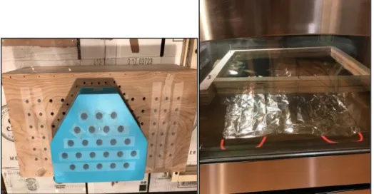
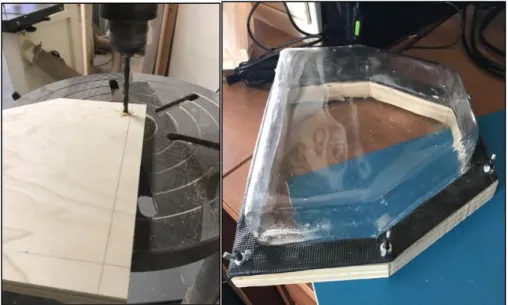
Figure 17: a) Left: Drilling of holes and b) Right: clamping during construction of vacuum
For the top grid plate, each hole was drilled using a bench drill. The placement of the holes was designed so that air would be removed uniformly across the thermoplastic sheet during the forming process.
Figure 18: a) Left: Construction of vacuum forming machine and b) Right: Final
In addition to the box, we had to construct a double frame to hold the thermoplastic sheets inside during the heating and forming process. Again, we chose maple for durability and used the same procedure to join the sides with the Domino to ensure resistance to air pressure during the vacuum sealing process. The dominoes were reinforced with polyvinyl acetate wood glue, clamped and allowed to dry overnight.
33
AUTONOMOUS CAMPUS MOBILITY PLATFORM
The final step in finalizing the vacuum forming machine was to create a mold of the layout of our components. The mold was 3D printed based on the size and configuration of the electronics placed at the front of the board. Unfortunately, the printing of the mold could not be achieved without holes which created significantly difficulty in the vacuum forming process. As a result, the holes had to be covered and solid wood molds were created in the same shape to facilitate the thermoforming process.
We were fortunate to have several sheets of commercial grade polycarbonate donated to our project by Mayfield Plastics of Sutton, Massachusetts to be used in creating our custom cover. Polycarbonate is a difficult material to work with as it is sensitive to temperature and humidity. Before attempting to form the enclosure on the vacuum forming machine, each sheet had to first be dried in the oven to prepare it for the process. Although the polycarbonate sheets all were similar in appearance, the time required for drying each varied considerably. On
average, the drying process required two hours of baking at 250 degrees Fahrenheit under careful scrutiny to avoid over drying and cracking. Each sheet had to be dried immediately prior to the thermoforming process and could not be done in advance. Sheets were individually placed in the wooden frame constructed for this process.
Figure 19: a) Left: 3D mold and b) Right: Frame view during process of oven
Once dried, each sheet was subsequently heated until the material achieved a softened and pliable state necessary for thermoforming. If the polycarbonate was heated for too long, bubbles formed, and it became stiff. Inadequate heating left the polycarbonate rigid and unable to form around the mold. After much trial and error, we determined that heating the
AUTONOMOUS CAMPUS MOBILITY PLATFORM
polycarbonate to 350 degrees Fahrenheit for thirty-two minutes yielded the ideal conditions for creating a cover on our vacuum forming machine.
Once removed from the oven, however, the polycarbonate would seize up quite quickly and become totally unusable for our purposes. Having the box and mold in place with the vacuum attached reduced the risk of loss of use of each polycarbonate sheet.
Figure 20: a) Left: Vacuum forming machine and b) Right: Attached vacuum
Several attempts were made to obtain a cover that was clear and free of bubbles and folds. Our final model was refined with the help of a heat gun used to smooth out the folds on the corners. After many attempts, we achieved a clear cover in the appropriate shape and size required for our purposes.
Figure 21: Final cover
Once the cover was ready, we needed to design a base with which the polycarbonate could be attached to the board. We determined that attaching the polycarbonate directly to the board would ultimately result in issues with possible breakage and damage to the board each time the fasteners needed to be undone. Realizing that the cover would likely need to be
35
AUTONOMOUS CAMPUS MOBILITY PLATFORM
removed frequently to access the electronics, we needed to consider alternate ways of attaching to the board. Our main focus was to maintain the integrity of the board and cover while allowing accessibility to the components.
To resolve this issue, we designed a base out of one piece of solid maple for rigidity and durability. After the design and pattern was created, the base was cut on a band saw. Holes were drilled in both the base and polycarbonate cover. We subsequently permanently affixed the maple base to the board with screws and the polycarbonate to the base with wing nuts. This design allows for easy removal of the cover for access to the electronic components. A watertight seal was added around the perimeter of the cover to further protect the electronics from the elements during operation.
AUTONOMOUS CAMPUS MOBILITY PLATFORM
7.2 Drive System
7.2.1 Drivetrain Design and Assembly
The drive motion of the longboard is achieved by a high torque motor connected to one of the rear wheels by a belt drive. There are four parameters that primarily contribute towards the design of the drivetrain:
i) the gear ratio (mG) - dictates the mechanical advantage at the wheel
ii) motor Kv - RPM per volt input (without load attached)
iiI) wheel diameter (d) - determines distance covered per revolution of wheel iv) voltage input to the motor - power supply to the system
Combination of these parameters give us the desired top speed and acceleration. According to the task specification, the maximum speed is 10 mph. Using the parameters defined above, we can calculate the maximum speed, 𝜐, output as follows:
𝑀𝑜𝑡𝑜𝑟 𝑅𝑃𝑀 = 𝑀𝑜𝑡𝑜𝑟 𝐾𝑣 × 𝑉𝑜𝑙𝑡𝑎𝑔𝑒 𝜐 = 𝑀𝑜𝑡𝑜𝑟 𝑅𝑃𝑀 × 𝑑 × 𝛱 × 1/𝑚𝐺 × 𝜀
𝑡𝑟𝑎𝑛𝑠𝑚𝑖𝑠𝑠𝑖𝑜𝑛
In the above equation, 𝜀 is multiplied to factor in the estimated efficiency of the
transmission. The drive train had been initially constrained by the wheel diameter size in order to ensure the steering motion does not cause collision of the wheels with the deck. Thus, the
diameter was limited to below 3.5” which gives the necessary clearance between the deck and the wheels. Second parameter that partially constrained the design was the teeth ratio of the timing belt pulleys commonly available for purchase and were small enough to fit under the board. Taking these constraints into account, with some iterations the following were finalized: 83 mm wheel, 16 teeth motor pulley, 36 teeth wheel pulley, 260 Kv brushless DC motor. Estimating an efficiency factor of 0.7, the required 10 mph is achieved with a voltage supply of 13 V.
Another parameter considered in the design were center distances of the pulleys. An optimum distance of 65-70 mm was determined to maximize the number of teeth in mesh to prevent belt slippage and minimize force acting on the motor mount. Thus the optimal belt length was calculated to be 265 mm.
37
AUTONOMOUS CAMPUS MOBILITY PLATFORM
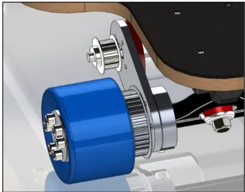
Figure 23: Basic Drivetrain setup without belt
Once the components were selected, we began the assembly by attaching the wheel pulley with the rear wheel. The aluminum pulley originally comes with tapped holes for fastening. It was securely attached to the wheel using 6 M5 bolts. However, first the
polyurethane wheel had to be drilled in the same bolt pattern using a hand drill and 6mm drill bit for the bolts to go through.
Figure 24: Wheel clamped for drilling bolt holes.
After attaching the pulley, the belt was put around the teeth, and the wheel was attached to the truck using a locknut. The motor pulley was secured on the motor shaft using a 3X3 mm key and two grub screws. Before tightening the screws, a small amount of Loctite was applied for thread locking to ensure robust assembly. The motor was mounted using four M4 bolts through counterbored slots on the motor mount. The slots allow sliding of the motor along the
AUTONOMOUS CAMPUS MOBILITY PLATFORM
length of the mount in order to adjust the tension in the belt. Once the belt was taut, the set screws on the motor mount were tightened to complete the drivetrain assembly.
Figure 25: Assembled drivetrain on rear truck
7.2.2 Motor Mount
The motor was mounted on the truck using a 2-piece motor mount. The first piece is a collar around the truck and is fixed to the truck using 4 set screws radially. The second piece is a 6 mm thick plate that is bolted to the collar on the truck and on the other side contains
counterbored slots to mount the motor using bolts. The 2-piece mount provides a rigid fixture preventing bending of the mount or relative motion between the components.
39
AUTONOMOUS CAMPUS MOBILITY PLATFORM
During our background research, we came across a number of reports that inadequately designed motor mounts undergo bending and warping. Thus, we decided to conduct a static analysis in SOLIDWORKS in order to simulate the forces the motor mount would withstand and the results thereof.
In this study, the material Al 6061 was assigned to the part. It has a yield strength of 270 MPa. It is assumed that the bolt connections between the mount and the collar around the truck create a fixed geometry on the faces highlighted in the figures below.
The back side of the mount where the collar acts as support, is also assumed as fixed geometry.
Following the fixtures, the loads were assigned in 2 parts. First load simulates the moment created by the motor’s weight acting towards the end of the mount. Since the weight acts at a distance away from the longitudinal axis of the mount, the moment was calculated as:
𝑀 = 𝑊 × 𝑟 = 10𝑁 × 0.025 = 0.25 𝑁. 𝑚
AUTONOMOUS CAMPUS MOBILITY PLATFORM
Since this moment could not be directly applied in the software, we assumed a distributed loading on the footprint of the motor on the mount, equivalent to the moment about the longitudinal axis. The figure below shows the load distribution from the back and side view.
The second load simulates the motor torque. We assume the worst-case scenario and use the value of the motor stall torque for maximum loading. The 2.7 Nm torque is applied to the faces where the bolts connect the mount and motor, shown in figure below.
Figure 29: Motor torque load
With these fixtures and loading, we ran our study and obtained the following results. The image below shows the stress distribution and an over-scaled deformation. The red zones show maximum stress occurring where the bolts are connected in the slot. The von Mises stress in that
41
AUTONOMOUS CAMPUS MOBILITY PLATFORM
area is 45 MPa, which sums up to a safety factor of 1.2. Since we already assume the worst-case scenario, the small safety factor was deemed acceptable.
Figure 30: Stress distribution on the mount
7.3 Steering System
Figure 31: Preliminary model for steering
Steering will be handled by one high-power servo motor driving a 16-tooth sprocket, via chain, to a 48 tooth sprocket that is attached to the front truck, thereby enabling steering of the board. The servo motor we are using is a Bosch seat motor commonly used for raising and lowering powered seats, generously donated by andymark.com (Figure 32, below).
AUTONOMOUS CAMPUS MOBILITY PLATFORM
Figure 32: Bosch seat motor servo for steering
The rated stall torque of 22 Nm with a 3:1 reduction, assuming a transmission efficiency of 90%, provides a maximum output torque of
Tout = (22 Nm)(48/16)(.9) = 59.4 Nm
to the front truck assembly, in order to allow turning of the wheelbase and thus, steering. The wheelbase has a diameter of 180 mm, thereby applying tangential forces of
((59.4 Nm)/2)/((.180 m)/2) = 330 N
to each of the wheels, which was deemed sufficient to allow turning under regular use. The top assembly plate holding the sprocket is bolted to the lower plate via four ½” bolts, and rests on an off the shelf thrust bearing in order to minimize friction between the mating surfaces (Figure 33, below). The thrust bearing is secured into the cutout in the board by a pair of counterbored plates, with the mating surfaces resting on it, with the aforementioned bolts passed through the central opening. The lower assembly is itself bolted to the truck mounting plate by an additional four ½” bolts, thus completing force transfer in a fairly efficient manner.
43
AUTONOMOUS CAMPUS MOBILITY PLATFORM
This design was chosen due to its relative simplicity, and the inexpensive (in terms of direct, budgeted costs) process of milling extruded aluminum bar stock into the desired form using the university’s machining resources. Of course, in production the machining process would actually represent one instance of an additional cost over the prototype, since the
machining equipment and time could no longer be provided for free by the university and MQP students, respectively.
All of the custom-made components of the board were first designed on SOLIDWORKS and then run through simulations. Once the parts were made we were able to test different materials to see which would not fail under the constraints we had. At first we decided on steel which passed the simulation tests and seemed like the best choice. Once we started machining the parts and assembling the board we realized that steel was too heavy to use so we went back to the SOLIDWORKS models and tested the components using 6061 Aluminum. After
analyzing each component, a second time we determined that 6061 Al is a more suitable material. We came to this conclusion but figuring out that the component with the greatest stresses on the part “adaptor_2”.
Figure 34: Adaptor 2
For the adaptor_2 component we applied a force of 200 lb acting down on the board. The adaptor_2 component is attached to the sprocket using four of the eight holes on the part. Since only four of the holes are being used we applied a disturbed torque of 380 ft.lb across the alternating holes. Using a tensile strength of 310 MPa for 6061 Aluminum the simulation provided a safety factor of 5.3 which deemed reasonable for this component. Since the component with the greatest stresses acting on it was efficient we concluded that all the components would work. We then machined the parts out of aluminum and installed the
AUTONOMOUS CAMPUS MOBILITY PLATFORM
components. Once the components were installed we stood on the board to and tested with various weights and none of the Aluminum components fractured. We also tested the Aluminum parts as a steering assembly and the wheels turned with minimal friction resulting in smooth data. The rest of the analyses of the other components can be seen in the Appendix D.
7.4 Structural Analysis of Steering Assembly
Assume a 200 lb person is traveling along at a leisurely pace of 1.4 m/s (normal walking speed for an average person). They hit a large buried rock, or the motor seized up, or anything happens to stop them dead. The handlebars stop their forward momentum in 0.1s (quick arrest being vital for the disabled rider to have any chance of maintaining balance).
𝐹 =𝐽
𝑡 =
(90.72 𝑘𝑔)(1.4 𝑚/𝑠)
0.1 𝑠 = 1270 𝑁
average force is exerted by handlebars on rider. Assuming the handle is a three-foot lever arm, torque is applied on the base plate.
(1270 𝑁)(0.9144 𝑚) = 1161 𝑁 ⋅ 𝑚
Assuming a brand-new assembly with no wear, defects, or loose fasteners, assuming the steel bolts do not cause the weaker aluminum to yield at all, either through shearing off the threads or pulling through the 0.08” (< 1.5*diameter = 0.195”) of material between the edge of the bolt and edge of the part on the bottom aspect, and assuming 80% of the counter torque is taken up by the bearing surface (design RoT),
(1161 𝑁 ⋅ 𝑚)(0.20)
0.01194𝑚 = 9,728 𝑁
tension is applied through the single loaded M4 bolt in the baseplate to supply the remaining counter torque.
The minimum ultimate tensile load of M4x0.7 grade 4.6 bolt (per AMES calculator) is 3,510 N << 9,728 N. Assuming the bolts were grade 12.9 and the handle was turned perfectly so that two bolts were engaged evenly, so in this case the bolts would not fail given these assumptions.
9728 𝑁
2 = 4,864 𝑁 < 10,700 𝑁(MUTL for grade 12.9 M4X0.7 bolts),
45
AUTONOMOUS CAMPUS MOBILITY PLATFORM
since the application of load over time will place significant stress on the hole edges, which are a scant 0.08” (0.61*hole diameter) from the edge of the plate on the inferior aspect, and four of the six bolts are 0.117” (0.9*hole diameter, see Figure 34) from the edge of the large bolt
counterbores on the superior aspect. These stresses are apt to result in small deformations, particularly in light of the grain structure of the extruded bar stock from which the part was turned, the play from which will make these sorts of failure even more likely.
Figure 35: Base plate hole dimension analysis
Assuming the bolt is threaded and engaged for the entire depth of the part, and again
assuming brand new parts with no creep and none of the above-described non-idealities we have
(0.5)(𝜋)(10.668 𝑚𝑚)(4 𝑚𝑚 − (0.64952𝑡ℎ𝑟)( 1
0.7 𝑡ℎ𝑟/𝑚𝑚) = 51.48 𝑚𝑚 2
effective thread shear area. Given the above-described scenario,
51.48⋅109728 𝑁−6 𝑚 2 = 189 𝑀𝑃𝑎 < 207 𝑀𝑃𝑎 (typical shear strength of 6061 aluminum). Now, assuming that no shearing of the threads occurs, tear out through the plate can be considered. If an M4 bolt is torqued in such a manner as to bear toward the counterbore of the large bolt on the superior face, and the plate edge on the inferior edge, it is therefore relying on .08” of aluminum (0.61*bolt diameter) on the inferior face and .117” (0.9*bolt diameter) on the superior face to retain it. To oversimplify a complex situation, considering this scenario as a simple shear tearout through the strongest aspect,
𝐹𝑓𝑎𝑖𝑙 = (30000 𝑝𝑠𝑖)(2)(0.117" + 0.065")(0.20") = 2,184 𝑙𝑏𝑓 = 9,714 𝑁,
somewhat greater than the order of what has been encountered in the other settings. Determining a value for the force applied is difficult given all that is going on, but failure here
AUTONOMOUS CAMPUS MOBILITY PLATFORM
also seems unlikely, despite the grain structure of extruded aluminum, which would make the plate more prone to fracture along that grain.
Finally, turning the handle against an immobilized wheelbase would result in single shear on the six bolts. For grade 4.6 bolts,
𝐹𝑓𝑎𝑖𝑙 = (6)(𝑈𝑆𝑆)(𝐵𝑆𝐴) = (6)(310 𝑀𝑃𝑎)(8.78 𝑚𝑚 2) = 16,330 𝑁.
This shear force would result from an axial torque of 𝜏𝑓𝑎𝑖𝑙 = (16330 𝑁)(0.0238 𝑚) = 388.6 𝑁 ⋅ 𝑚.
Assuming the handlebars are one foot wide from grip to grip, an applied torsional force of 𝐹𝑏𝑎𝑟 =388.6 𝑁⋅𝑚
0.1524 𝑚 = 2,550 𝑁
at the handlebars would be sufficient to shear the M4 bolts off, so were the stop to occur in such a way that the wheels were immobilized, and one side of the handlebars took the brunt of the force, failure is somewhat likely.
Analysis: given the multiple possible modes of failure, securing the joint with the weaker fasteners may be necessary in order to act as a mechanical fuse. Grade 4.6 bolts provide the lowest bar to failure in all areas, and therefore would serve this purpose of failing without destroying the assembly. Notably, assumptions had to be made regarding the stopping time; no consistent and reliable information could be located on reasonable values, and we lacked the equipment to test this empirically. This means that, depending on the stopping time, the
calculated stresses experienced could be higher or lower. Due to this, more rigorous testing will have to be implemented prior to release of the project as a product, and a software-based speed control to limit the forces experienced will have to be implemented to ensure safe operation of the device.
The remaining parts have the same bearing surface area and the same number of the same-sized fasteners resisting the same loads as the first part in compression and tension, and thus should yield the same (well within any reasonable margin of safety) results in those aspects, so we will forego repeating those calculations.
For the adaptor, tearout through the “plate” edge, assuming the minimum diameter throughout, much higher than is likely.
47
AUTONOMOUS CAMPUS MOBILITY PLATFORM
For all of the parts secured for torsion by four ¼” bolts, assuming the single-shear
characteristics are the same, and the bolts are grade 2, if the bearing part is immobilized and a force is applied to the part in question, produces single shear failure of the four bolts.
𝐹𝑓𝑎𝑖𝑙 = (𝑈𝑆𝑆)(4)(𝐵𝑆𝐴) = (45000 𝑝𝑠𝑖)(4)(0.04908 𝑖𝑛 2) = 8,716 𝑙𝑏𝑓 = 38,770 𝑁
This corresponds to an axial failure torque of much greater than that of the M4 bolts.
𝜏𝑓𝑎𝑖𝑙 = (𝐹)(𝑟) = (38770 𝑁)(0.01397 𝑚) = 541.6 𝑁 ⋅ 𝑚,
Analysis: the remaining parts, all essentially thick plates with large bearing surfaces, taking minimal load and secured by four large fasteners, are not likely points of failure for this assembly.
7.5 Power Distribution
The board components are all powered by a 6S2P (6 series, 2 parallel) 18650 (Samsung 20R cells) battery pack, sourced from diyelectricskateboard.com and designed for this specific purpose. This particular pack contains both the standard 6S (6*3.7 V = 22.4 V) output, as well as two USB ports providing standard USB 5V to power a Raspberry Pi and an Arduino, as well as an integrated battery management system designed for motorized skateboards such as this one. Power was drawn from the battery via all three routes, as seen below in Figure 35.
Figure 36: Electrical Diagram
The primary (6S) power output was routed to the electronic speed controller (ESC) for the motor, which in turn managed the power supplied to the drive motor, and thus ultimately the drive speed. The control electronics, specifically the Raspberry Pi and Arduino, were powered by the two USB ports, as per the designs on diyelectricskateboard.com. The steering servo
AUTONOMOUS CAMPUS MOBILITY PLATFORM
motor was powered via a Pulse-Width Modulation (PWM) output from the Arduino; there was initially concern that the current supplied by the Arduino might not be sufficient to provide adequate torque for this purpose, but that does not appear to have been an issue with appropriate mechanical advantage from the chain and sprocket described elsewhere.
Using the provided 2A charger, the skateboard battery was able to be charged in 2-3 hours, again per the given specifications, thus fulfilling the secondary specification TSS04. This could be further improved by purchasing the 4A fast charger also offered by
diyelectricskateboard.com, though it was ultimately decided to forego this for budgetary reasons, particularly as the specification had already been achieved.
The 6S2P 18650 pack provides 4000 mAh rated, for 25.2 V * 4 Ah = 100.8 Wh rated power supplied, while typical power consumption from the ESC under typical conditions was found to be 13V. From our experiments the battery last 2 hours at 50% idle time.
7.6 Thermal Design
The inside of the electronics enclosure contains many heat-sensitive components and heat generating components. The steering motor controller is the largest heat generator. As the
steering motor has a worm gearbox it is <20% efficient. This lack of efficiency causes the motor and motor controller to give off the excess energy as heat. We ran a simulation in
SOLIDWORKS to estimate the heat generation and temperature inside the enclosure.
To validate the study, we placed temperature sensors inside the enclosure at the points specified in figure 36.
49
AUTONOMOUS CAMPUS MOBILITY PLATFORM
First, the board was switched on and steering was run intermittently for 10 minutes without a fan on the motor controller. The temperature was recorded with an Arduino Uno and all components were allowed time to cool. The fan was then mounted onto the motor controller and the test was re-run. The results from these tests are shown in figures X and Y.
Figure 38: Enclosure Temperature Readings without Fan
Figure 39: Enclosure Temperature readings with Fan
The normal operating temperature of the enclosure drops approximately 5 degrees with the addition of a fan on the motor controller.
Time (s) Temperature (c)
Time (s) Temperature (c)
AUTONOMOUS CAMPUS MOBILITY PLATFORM
8. Sensing and Control
8.1 Sensors
The sensors used on this robot serve two primary purpose- robot localization and obstacle detection. In order to aid localization of the robot in the global coordinate frame, we have used a Global Positioning System (GPS) module and a magnetometer as