Open Loop and Closed Loop Power Control Analysis on
LTE
Norma Amalia1*,Eka Setia Nugraha2, Muntaqo Alfin Amanaf3
1,2,3Institut Teknologi Telkom Purwokerto
1,2,3 Jl. D.I Panjaitan No. 128 Purwokerto, Banyumas, Jawa Tengah, Indonesia
*Corresponding email: [email protected]
Received 11 September 2018, Revised 02 October, Accepted 26 November 2018
Abstract - LTE downlink is using Orthogonal Frequency Division Multiple Access (OFDMA) multiple access system which have high invulnerability from multipath problem. One of the weakness of OFDM system is the high level from Peak to Average Power Ratio (PAPR) that requires higher level transmit power for maintaining the Bit Error Rate (BER) requirement. Using uplink scheme with Single Carrier FDMA (SC-FDMA) which is OFDMA modification, will be offered better level of PAPR than its conventional OFDM. The main problem of using OFDMA is the high level of PAPR, while using SC-FDMA the problem is intra-cell interference. Intra-cell or inter-cell interference is the common problem that can reduce the LTE performance. Minimizing received power for each users (UE) which is still at acceptable tolerance parameter, can be used for reducing the interference problem to another UE. Power control is the appropriate solution for minimizing the interference level. In this paper will be analyzed the power control using open loop and closed loop scheme at LTE network. The simulation result shows that without power control schemes, the transmit power of UE was 23 dBm. While, after applying power control scheme, the transmit power was 18.8 dBm at α=0.4 of open loop condition and 9.05 dBm at closed loop condition. Using this transmit power value as the UE power can improve the SINR performance. The SINR average value without power control scheme was only 20.38 dB which is lower than using open loop scheme was achieved 22.44 dB, and 24.02 dB at closed loop scheme.
Keywords – LTE, power control, open loop, closed loop, SINR
All rights reserved.
I. INTRODUCTION
The development of telecommunication was increasing rapidly, especially at cellular communication technology. There are many significant enhancements technology from GSM to the LTE network at cellular communication tecnology [1]. Long Term Evolution (LTE) is designed to comply the necessary of high data rate and high capacity communication media at 100 Mbps peak data rates of downlink (DL) and 50 Mbps for uplink (UL) [2]. Those ability requirement can be achieved by some functional modification of LTE involve its multiple access technology. At LTE downlink, the recently used of multiple access technique is Orthogonal Frequency Division Multiple Access (OFDMA) that can reduce multipath effect [3]. While the OFDMA disadvantage is high level of Peak to Average Power Ratio (PAPR) which is required high level of transmit power for
holding the Bit Error Rate (BER) requirement [4]. The suitable scheme for uplink is Single Carrier FDMA (SC-FDMA) [3] that is modified OFDMA for receiveing better level of PAPR.
Using orthogonal transmission scheme for eliminating the mutual interference between users (UE) at the same cell, is called as intra-cell interference. However, the transmission scheme at the neighbour cell is not orthogonal that can make interference between UE to its neighbour cell which called inter-cell interference. This condition can be restricted the capacity performance of this system. 3GPP LTE is designed for maximizing the spectrum efficiency, such as frequency reuse 1 at downlink and uplink condition. It means that all cell at those networks will be used same frequency. Using frequency reuse 1 make data and control channel sensitive to the inter-cell interference condition. The Copyright © 2018 JURNAL INFOTEL
cell edge performance and cell cite capacity can be confined by inter-cell interference [5].
The commonly problem at SC-FDMA technology is intra-cell interference. All types of interference involve intra-cell and inter-cell interference can reduce the network performance. At multi user environment, some UE have to share the same radio resource for achieving the spectrum efficiency [6]. Using the same channel can cause the signal for certain UE will cover the other UE which is make interference and also quality performance reduction.
Using low power level that still at acceptable tolerance parameter for UE is one of solution for minimizing the interference level. Low power level can be obtained from power control method [7]. The role of power control is giving the required SINR to preserve received level at eNB to the UE communication link. Power control will also manage the interference level from its neighbour cell.
Many researchers have been implemented the power control method to the various field such as, devive to device (D2D) communication [8], cognitive radio networks [9], and also LTE power control system. LTE power control scheme has been studied before at [10]-[13]. Power control techique that have more advantage than before will be used for determining some criteria at using closed loop correction has been proposed in [10]. Using nonlinear Potential Feedback Control (PFC) for applying open loop power control technique at LTE uplink transmission has been evaluated by [11]. Open loop scheme from [12] [13] are also analyzed according to its FPC scheme at SINR performance which can give sub-optimal configuration for interference scenario and its limited noise.
Power control is also implemented to the heteregeneous network. Heteregeneous network application is development from LTE-Advanced which have various resource such as femtocell and small cell network. The result from [14] showed that open loop power control scheme for femtocell network is effectively reduce interference level and also improve the LTE-Advanced performance especially at SINR, throughput and Bit Error Rate (BER).
According to the previous research, power control is the effective method for improving the performance, optimizing the capacity and also intensify the lifetime of battery. In this research will be analyzed the power control system using open loop and closed loop scheme at LTE uplink transmission.
The main concept of power control is using minimum power level to get the required SINR. In this
paper, we analyzed two conditions of UE i.e. with and without power control scheme. In without power control scheme, all UE was using the same value of power level resource whereas after applying the power control, the value of power level resource was different that depends on the scheme type of power control. The received power of UE was assumed at random condition based on the distance to the eNB and also its received losses. The analysis parameters of this research were transmit power level, SINR, throughput and interference level power at those two conditions, before and after power control implementation using open and closed loop scheme.
II. RESEARCH METHOD A. Network Topology
There are three main steps of this research, those are LTE network modeling system including the UE and eNB position, apply the open loop and closed loop scheme of power control system with some various alpha parameters, and analyze the simulation result.
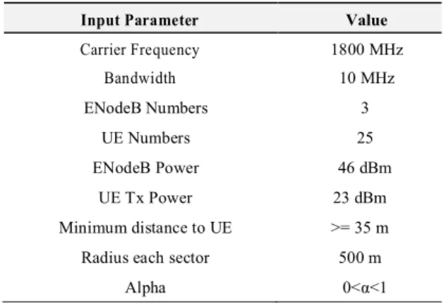
In this simulation will be modeled LTE network with some uniformly UE at line of sight (LOS) condition. LTE which is macrocell network is called by eNB. eNB network layout design will be described in hexagonal cell that have three sectors. There are 25 UE dropped uniformly at each eNB sectors. The relevant guidelines of simulation are listed in Table 1 which is used for eNB and UE at LTE uplink transmission.
Fig.1. LTE Modeling System
There are three numbers eNB of this system as shown at Figure 1. The main eNB will be contained the uniform UE of each sector. While the other eNB are assumed as neighbour cell that make interference to the main eNB system. This research was using frequency 1 deployment. It means that the three eNB using same
frequency. The transmit power of eNB is constant at 46 dBm. Due to the uplink power control system, the transmit power of UE will modified from 23 dBm to the certain level based on result from power control system.
Table 1. Input Parameter
Input Parameter Value
Carrier Frequency 1800 MHz Bandwidth 10 MHz ENodeB Numbers 3 UE Numbers 25 ENodeB Power 46 dBm UE Tx Power 23 dBm Minimum distance to UE >= 35 m Radius each sector 500 m
Alpha 0<α<1
LTE propagation models are vital in the calculation pathloss from eNB to the UE. The developed system is based on eNB to UE pathloss model from 3GPP standarizations. The pathloss between eNB and UE in LOS condition is calculated as:
= 15.3 + 37.6 [ ] (1)
R is the distance of UE to the eNB in meters. The distance calculation is adopted from euclidean calculation as:
= ( − ) + − [ ] (2) x,y are representation of transmitter or receiver coordinates from its random position. Due to the uplink transmission of this system, the received power is calculated from UE to the eNB. The equation for calculating received power of eNB from UE is derived as:
Pr = − − ℎ [ ] (3) The received power calculation are determined from transmit power of UE 23 dBm subtracts with PL from eq. (1) and shadowing value. In this paper we assumed shadowing at 4 dB for urban environment condition. B. Power Control System
The goal of power control is manage the transmit power level output from the transmitter. There are two types of power control according to its transmission mechanishm. Downlink power control can manage the transmit power level at BTS side, while the uplink transmission will control the transmit power level at UE side. Uplink power control mechanism was used in this system. The transmit power of UE with some
parameters that have been received at eNB (PPUSCH)
can be calculated using following equation:
= { , + 10. + . } [ ] (4) is the maximum power level that is allowed by system, the value of maximum power was 23 dBm adjust to the UE transmit power. M is the Physical Resource Block (PRB) number which was 50 PRB numbers. While α is the pathloss compensation factor at the range of 0 to the 1. P0 is the cell spesific
parameter in dBm unit. The value of P0 can be obtained
by summing maximum value of received power eNB to UE and its maximum pathloss value for each sector.
= max , , + max , , [ ] (5)
C. Open Loop Power Control
Open loop power control is the ability of UE as the transmitter to control the uplink power which is suitable for the receiver. This controlling scheme is adjusted to the eq (4) calculation. Basically, the open loop is adopted to the conventional power control scheme. The election of α value depends on some conditions. If α = 1 is compatible for conventional power control scheme, while 0<α<1 is for fractional open loop power control scheme. In this paper we used fractional open loop power control scheme for determining the α value.
D. Closed Loop Power Control
The difference of closed loop power control to the open loop power control is the additional step of loop correction value which is also known as transmit power control (TPC) commands. The advantage of closed loop can estimate the SINR of received signal with the desired SINR target value. TPC command will request to the UE for raising or reducing the power level if the SINR is below the SINR target. The UE adjusts its uplink transmit power based on TPC command which is received from eNB [5]. The correction value for this closed loop power control scheme is derived as:
( ) = ( − 1) + − 4 [ ] (6)
TPC command [-1, 0, 1, 3] dB was used during the simulations. f (0) = 0 and 4 were the transmission time intervals. According to the correction value, the closed loop power can be calculated using following equation:
= min{ , ( ) + ( )} [ ] (7)
Closed loop power control is also calculated using open loop power control reference (POL) that is added
by correction value. According to the power control calculation, the performance of SINR and throughput can be determined.
E. SINR, Throughput, dan Interference Level
In this simulation the performance influence of the open loop and closed loop power control to the SINR and throughput value will be analyzed. SINR performance can be modeled by this following equation:
SINR = 10 log
, ,
[ ] (8)
SINR is calculated using received power of eNB to the UE at uplink transmission (Pr) to the N as the noise
and interference level total. N is the thermal noise in this system. While IeNBUE is the interference level of the
eNB at uplink transmission from the other nearest neighbour cell. The interference source of the eNB based its interference source was calculated by this equation:
I = ∑ Pr (9) Interference level can be calculated from received power level of co-channel eNB (Prn) at uplink
transmission. In this system, there are two neighbour cells of eNB. Then, throughput performance system can be expressed by Shannon formula as:
Throughput = B log (1 + SINR) (10) B is the number of bandwidth on each resource block user at 180 KHz.
III. RESULT
In this section will discuss the simulation result to the determine the effect of open loop and closed loop power control deployment in LTE network. Compare and analyze the interference level power, SINR and throughput performance of system when using normal transmit power and minimizing power output from power control scheme.
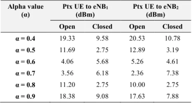
Table.2. UE Transmit Power after Power Control
Alpha value (α) Ptx UE to eNB1 (dBm) Ptx UE to eNB2 (dBm) Open Closed Open Closed α = 0.4 19.33 9.58 20.53 10.78 α = 0.5 11.69 2.75 12.89 3.19 α = 0.6 4.06 5.68 5.26 4.61 α = 0.7 3.56 6.18 2.36 7.38 α = 0.8 11.20 2.75 10.00 2.75 α = 0.9 18.38 9.08 17.63 7.88
This Simulation measure Ptx UE to eNB1 and eNB2 to simulate the power transmit of UE when using Open loop and Close loop power control method. The measurement Result at table 2 Ptx UE to eNB1, for alpha 0.4 to 0.9, open loops have a higher Ptx average than the closed loop. However, when alpha 0.6 and 0.7 closed loop has higher Ptx than the open loop. At alpha 0.6 and 0.7, the UE transmit power is the smallest. Table 3. Average Performance of SINR and Throughput Before and After Power Control
Average Performance Interference Power (dBm) SINR (dB) Throughput (Mbps) Without Power Control -105.41 22.41 0.35
Using Power Control Open Closed Open Closed Open Closed
α = 0.4 -108.44 -115.66 24.42 26.85 0.39 0.45 α = 0.5 -116.07 -112.16 27.38 28.05 0.47 0.49 α = 0.6 -123.70 -123.42 28.25 28.24 0.501 0.501 α = 0.7 -125.43 -122.92 28.32 28.18 0.504 0.49 α = 0.8 -117.80 -125.58 27.68 28.33 0.48 0.504 α = 0.9 -111.31 -116.5 25.63 27.16 0.43 0.46
The analysis for the result of interference power, SINR and Throughput show that both power control method can decrease interference power and can increase SINR, Throughput. If both power control open loop and closed loop compared to the parameter alpha 0.4 to 0.8, it can be concluded that until alpha 0.8, closed loop power control method decreases
interference power also increases the SINR and throughput than open loop power control.
Fig.2. Throughput Average
In Fig.2, we can see that without power control graph has lower average throughput than with power control scheme. It shows the Probability under 0,2 Mbps at Without power control method is about 0.2, it is lower than with power control method. The comparison of both methods, power control between open loop power control and close loop power control, could be showed by the alpha 0,4, the closed loop method has the higher throughput than open loop. When throughput more than 0.4 Mbps close loop power control method has probability 0.5 whereas open loop power control 0.4. The alpha or propagation affects the throughput at open loop power control method.
Fig.3. SINR Average
Figure 3 shows that the close loop power control method has the higher Average SINR than open loop power control method and without power control method. The effect of alpha mostly affects the open loop power control method. It makes the SINR become
higher. When alpha 0.4 to 0.8, the higher alpha make the Average SINR increased.
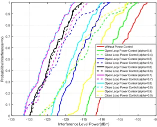
The Interference level power for the alpha 0.4 at both power control method concludes the close loop power control has the lower interference level power than open loop method. The effect of alpha makes the interference higher. At alpha 0.4 to 0.8, the higher alpha makes the interference level power increasing. The comparation power control method and without power control method is shown at the Fig 4 the scenario without power control has the higher interference level power.
Fig. 4. Interference Level Power
IV. DISCUSSION A. Transmit Power Level Modification
There was some reduction power transmit level of UE after adding power control scheme at this system. The transmit power level of UE at normal condition was 23 dBm. While at power control deployment, the transmit power of UE decreased to the 19.33 dBm for eNB neighbour 1 and 20.53 dBm eNB neighbour 2. This reduction of each neighbour cell is different due to the pathloss influence of the UE to its neighbour. This condition shows that using power control scheme has lower transmit power than without power control. Using lower transmit power will influence the interference level performance which is discussed at the next section.
B. Performance Analysis of SINR and Throughput Based on the simulation result, the interference level without using power control was -105.41 dBm that is larger than using open loop power control with α = 0.4 the interference level was only -108.44 dBm. Reducing the interference power level will boost up SINR value, on the contrary, increasing this will lower
0 0.2 0.4 0.6 0.8 1 1.2 1.4 Throughput Average(Mbps) 0 0.1 0.2 0.3 0.4 0.5 0.6 0.7 0.8 0.9 1
Without Power Control
Open Loop Power Control (alpha=0.4) Close Loop Power Control (alpha=0.4) Open Loop Power Control (alpha=0.5) Close Loop Power Control (alpha=0.5) Open Loop Power Control (alpha=0.6) Close Loop Power Control (alpha=0.6) Open Loop Power Control (alpha=0.7) Close Loop Power Control (alpha=0.7) Open Loop Power Control (alpha=0.8) Close Loop Power Control (alpha=0.8) Open Loop Power Control (alpha=0.9) Close Loop Power Control (alpha=0.9)
P ro b a b ili ty (S IN R < = x) -135 -130 -125 -120 -115 -110 -105 -100 -95
Interference Level Power(dBm)
0 0.1 0.2 0.3 0.4 0.5 0.6 0.7 0.8 0.9 1
Without Power Control Open Loop Power Control (alpha=0.4) Close Loop Power Control (alpha=0.4) Open Loop Power Control (alpha=0.5) Close Loop Power Control (alpha=0.5) Open Loop Power Control (alpha=0.6) Close Loop Power Control (alpha=0.6) Open Loop Power Control (alpha=0.7) Close Loop Power Control (alpha=0.7) Open Loop Power Control (alpha=0.8) Close Loop Power Control (alpha=0.8) Open Loop Power Control (alpha=0.9) Close Loop Power Control (alpha=0.9)
SINR value. It proves that using open loop power control the SINR performance was greater around 2.01 dB at 24.42 dB, while without power control the SINR performance was only 22.41 dB.
The increasing of SINR at open loop power control deployment is directly proportional to the increasing of throughput performance. It shows, the throughput value without power control was lower 0.04 Mpbs than using power control at 0.39 Mpbs. Therefore, using power control deployment can reduce the interference level that can improve the SINR and throughput performance of this system.
C. Open Loop dan Close Loop Power Control In this sub section will discuss the simulation result to compare and analyze the performance of this system after using open loop and closed loop power control scheme. Based transmit power level data which was presented at Table 2, the transmit power value using closed loop scheme is lower than using open loop scheme. Using open loop scheme with α = 0.4, the transmit power level UE to the eNB1 was 19.33 dBm while using closed loop was only 9.58 dBm. The main factor which caused the transmit power result was the closed loop scheme calculation was using open loop power with normal as the reference comparison. According to that calculation, the output result of closed loop power was definitely lower than open loop power. As well as using α = 0.8, the transmit power level at closed loop scheme was only 2.75 dBm and open loop scheme was 11.20 dBm. Furthermore, the TPC command also supported the minimizing power of closed loop scheme.
The lowest transmit power of neighbour cell will influence directly to the interference level of this system. Using closed loop scheme the interference level is -115.66 dBm which is lower than open loop scheme at -108.44 dBm. The interference power level reduction will also influence to the SINR performance. The closed loop scheme deployment have SINR value with the range of 20 dB to 35 dB. While using open loop scheme has some lower SINR at 0.4 to 0.9 CDF only achieved < 30 dB as shown at Fig. 3. The SINR improvement of using closed loop scheme can make the increasing to the throughput performance also.
V. CONCLUSION
In this paper propose power control deployment at LTE uplink network. The power control deployment is using open loop and closed loop scheme based on alpha modification. The closed loop scheme based on TPC command and open loop power level reference provides better performance at SINR and throughput
result. The performance of this system represented as SINR and throughput CDF graphic. The performance result from open loop and closed loop power control is better at alpha 0.8. The lower transmit power of closed power scheme given highly to SINR and throughput performance is around 0.25 times better than without power control.
ACKNOWLEDGMENT
This research is supported by Kemristekdikti Indonesia from grant assistance of Penelitian Dosen Pemula (PDP) in period of 2017-2018.
REFERENCES
[1] Tran, Thien-Toan, Yoan Shin, and Oh-Soon Shin.
"Overview of enabling technologies for 3GPP
LTE-advanced." EURASIP Journal on Wireless
Communications and Networking 2012.1 (2012): 54. [2] Talukder, Z. H., et al. "Cell coverage evaluation for
LTE and WiMAX in wireless communication system." World Applied Sciences Journal, vol.22, no.10, pp. 1486-1491. 2013.
[3] Arfianto, Muhammad Dimas, Ridha Muldina Negara,
and Indrarini Dyah Irawati. "Analisa Performansi Algoritma Penjadwalan Proportional Fairness Dan Log Rule Dengan Skenario Multicell Pada Sistem 3GPP LTE." Jurnal Infotel, vol. 8, no. 1, pp. 24-34, 2016.
[4] Paredes, Martha C. Paredes, and M. García. "The
problem of peak-to-average power ratio in OFDM systems." arXiv preprint arXiv:1503.08271 (2015).
[5] MUHAMMAD, Bilal; MOHAMMED, Abbas.
Performance evaluation of uplink closed loop power control for LTE system. In: Vehicular Technology Conference Fall (VTC 2009-Fall), 2009 IEEE 70th. IEEE, 2009. p. 1-5.
[6] RACHMAPRAMITA, Arum; ADRIANSYAH,
Nachwan Mufti; SYIHABUDDIN, Budi. Analisis Koeksistensi Jaringan LTE Non Lisensi dan Wi-Fi Pada Frekuensi 5GHz. JURNAL INFOTEL, [S.l.], vol. 9, no. 3, pp. 299-304, aug. 2017
[7] Chiang, Mung, et al. "Power control in wireless cellular networks." Foundations and Trends® in Networking, vol.2, no. 4, pp. 381-533, 2008.
[8] KWAK, Yongjun, et al. Performance evaluation of
D2D discovery with eNB based power control in LTE-advanced. In: Vehicular Technology Conference (VTC Fall), 2014 IEEE 80th. IEEE, 2014. pp. 1-5.
[9] Amalia, Norma, and I. Wayan Mustika. "Study on
feasible solution of power control in cognitive radio
networks." Smart Green Technology in Electrical and
Information Systems (ICSGTEIS), 2014 International Conference on. IEEE, 2014.
[10] Quintero, Nestor J. "Advanced power control for
UTRAN LTE uplink." Master of Science Thesis, Aalborg University (2008).
[11] Phan, Dat-Duong, et al. "Potential feedback control for the power control in LTE." IEEE Transactions on Automatic Control, vol. 60, no. 9, pp. 2506-2511, 2015.
[12] Berger, Sascha, et al. "Dynamic Range-Aware Uplink
Transmit Power Control in LTE Networks:
Establishing an Operational Range for LTE's Open-Loop Transmit Power Control Parameters $(\alpha, P_ {0}) $." IEEE Wireless Communications Letters, vol. 3, no. 5, pp. 521-524, 2014.
[13] CASTELLANOS, Carlos Ubeda, et al. Performance of
uplink fractional power control in UTRAN LTE. In: Vehicular Technology Conference, 2008. VTC Spring 2008. IEEE. IEEE, 2008. pp. 2517-2521.
[14] FEBRYANTI, Safirina; HENDRANTORO,
Gamantyo; KUSWIDIASTUTI, Devy. Analisis
Kinerja Metode Power Control untuk Manajemen
Interferensi Sistem Komunikasi Uplink
LTE-Advanced dengan Femtocell. Jurnal Teknik ITS, vol. 2, no. 2, pp. A355-A360, 2013.
[15] 3rd Generation Partnership Project; Technical
Specification Group Radio Access Network; Evolved Universal Terrestrial Radio Access (E-UTRA); TDD Home eNode B (HeNB) Radio Frequency (RF) requirements analysis (Release 13) 3GPP TR 36.922 V13.0.0 (2016-01).