www.dimond.co.nz 0800 ROOFSPEC (0800 766 377)
As part of Dimond’s policy of continuing product and system development the company reserves the right, at any time and without notice, to discontinue or change the products, materials, design advice, features or specifications represented in this Manual without incurring any liability. The information in this Manual is issued for general application in New Zealand, and should not be treated as a substitute for detailed technical advice in relation to requirements for individual projects in New Zealand or overseas. To the extent permitted by law, Dimond disclaim any liability for loss or damage incurred by the use of the information in this Manual unless it is covered by a specific warranty agreement.
Dimond, a division of Fletcher Steel Ltd
June 2013
ROOFING AND
CLADDING
SYSTEMS GUIDE
This guide is an extract from the Dimond Roofing andCladding Systems Manual and it is to be read in conjunction with the full Dimond Roofing and Cladding Systems Manual available at www.dimond.co.nz under the Architects/Specifiers section. This guide will not be updated by Dimond and it is intended that the user updates this guide using the current Dimond Roofing and Cladding Systems Manual on our website.
For online technical information
visit the Architects section at www.dimond.co.nz
Contact your Dimond Sales Centre:
0800 DIMOND (0800 346663)
For Sales, Delivery, Availability & Pricing Information
Roofing & Wall Cladding Systems 2.1.1.2 Environment
2.1.1.3 Warranty
2.1.3.1 Profile Span & Curvature Quick Guide 2.1.3.3 Dissimilar Materials
2.3.1 Handling & Storage 2.3.2 Layout & Fastening 2.3.3 Flashings / Penetrations 2.3.4 General Workmanship
ROOFING AND
WALL CLADDING
SYSTEMS GUIDE
THE WAY TO INSPIRED
DESIGN CHOICES…
DIMOND ROOF, WALL AND
GUTTER SYSTEMS
RAINW A TER SYSTEMS MET AL TILE SYSTEMS NA TURAL LIGHTING & CURVED ROOFING SYSTEMS SPECIFIC DESIGN B Y PROFILE ROOFING & W A LL CLADDING SYSTEMSRoofing and Wall Cladding Systems Performance
May 2006
2.1.1.2 ENVIRONMENT
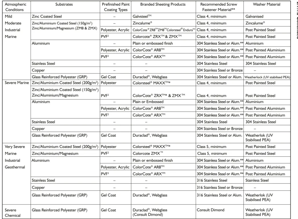
AS/NZS 2728: 1997, (Australia/New Zealand Standard – Prefinished / Prepainted Sheet Metal Products For Interior / Exterior Building Applications – Performance Requirements), classifies the atmospheric environment into 7 categories and provides a guide to the selection of prefinished products in these categories.
In Table 2.1B and 2.1C overleaf we have created a guide showing which categories the more common roofing and cladding materials and coatings can be used in. Only 6 of the 7 categories defined by the standard are covered, as the 7th one, Tropical, is not relevant in New Zealand.
For further classification information please refer to AS/NZS 2728:1997
Table 2.1B Atmospheric Classification Definition
Mild sheltered areas that are far inland (very few in NZ)
Moderate areas that are protected from marine influence. Are inland areas other than those d n a l n i r a f e r a t a h t
Industrial industrial areas that are inland
Marine large parts of NZ including areas 100m – 400m from the shoreline in sheltered areas (inner harbour and estuaries) and more than 1 km from breaking surf shoreline. Can extend up to 30kms inland depending on topography and prevailing winds.
Severe Marine areas that range from 100m to 1km from breaking surf shoreline. In high wind areas the distance inland will increase. It also includes areas that are less than 100m (but can extend up to 400m depending on prevailing winds) from the shoreline in sheltered areas.
Very Severe Marine in areas up to and including 100m from breaking surf. Will extend inland 400m or more where strong prevailing winds exist.
Industrial & areas of high corrosion including chemical plants and geothermal areas. Geothermal
Severe Chemical unusually harsh conditions due to moisture generation and/or chemical usage or Environments storage (eg. cool stores, animal shelters, fertiliser storage). Will require specific (additional to material selection for sheeting, fasteners and netting. Contact Dimond.
R
oofing and W
all Cladding Systems P
erformance June 2013 c i r e h p s o m t
A Substrates Prefinished Paint Branded Sheeting Products Recommended Screw Washer Material
Conditions Coating Types Fastener Material**
Mild Zinc Coated Steel – GalvsteelTM Class4,minimum Galvanised
Moderate Zinc/Aluminium Coated Steel (150g/m2) – Zincalume® Class4,minimum Zincalume®
Industrial Polyester, Acrylic ColorCote®ZR8 ZM8 Colorsteel EnduraTM Class4,minimum Post Painted Steel
Marine PVF2 Colorcote® ZRXTM Class4,minimum Post Painted Steel
Aluminium – Plain or embossed finish 304 Stainless Steel or Alum.** Aluminium
Polyester, Acrylic ColorCote® AR8TM 304 Stainless Steel or Alum.** Post Painted Aluminium
PVF2 ColorCote® ARXTM 304 Stainless Steel or Alum.** Post Painted Aluminium
Stainless Steel – – 304 Stainless Steel 304 Stainless Steel
Copper – – 304 Stainless Steel or Bronze –
Glass Reinforced Polyester (GRP) Gel Coat Duraclad®, Webglass 304 Stainless Steel or Alum. Weatherlock (UV stabilised PEA)
Severe Marine Zinc/Aluminium Coated Steel (200g/m2)
Zinc/Aluminium Coated Steel (150g/m2)
Polyester Colorsteel® MAXXTM* Class4,minimum Post Painted Steel
PVF2 ColorCote® ZRXTM* Class4,minimum Post Painted Steel
– Plain or Embossed 304 Stainless Steel or Alum.** Aluminium
Polyester, Acrylic ColorCote® AR8TM 304 Stainless Steel or Alum.** Post Painted Aluminium
2
PVF ColorCote® ARXTM 304 Stainless Steel or Alum.** Post Painted Aluminium
Stainless Steel – – 304 Stainless Steel 304 Stainless Steel
Copper – – 304 Stainless Steel or Bronze –
Glass Reinforced Polyester (GRP) Gel Coat Duraclad®, Webglass 304 Stainless Steel or Alum. Weatherlok (UV
Stabilised PEA)
Very Severe Zinc/Aluminium Coated Steel (200g/m2) Polyester Colorsteel® MAXXTM* Class5,minimum Post Painted Steel
Industrial Aluminium – Plain or embossed finish 304 Stainless Steel or Alum.** Aluminium
Geothermal Polyester, Acrylic ColorCote® AR8TM 304 Stainless tee oS l r Alum.** Post Painted Aluminium
304 tainless S l or Al m.*
Stainless Steel – – 316 Stainless Steel Stainless Steel
Copper – – 316 Stainless Steel or Bronze –
Glass Reinforced Polyester (GRP) Gel Coat Duraclad®, Webglass 316 Stainless Steel or Alum. Weatherlok (UV
Stabilised PEA)
Severe Glass Reinforced Polyester (GRP) Gel Coat Duraclad®, Webglass Consult Dimond Weatherlok (UV
Chemical (Consult Dimond) Stabilised PEA)
*Use of coil on cut edge protection lacquer may be required. Alum. = Aluminium Alutites for timber only. ** Stainless steel fasteners must be installed with clearance and separation to avoid contact with Aluminium.
®
PVF2 ColorCote ARXTM S tee u * Post Painted Aluminium
Table 2.1C Environment Categories and Suitable Sheeting and Fastener Materials
2.1.1.2 Continued
& ZMXTM
& ZMXTM
Zinc/Aluminium/Magnesium PVF 2 Colorcote ZMX TM
Class 5, minimum Post Painted Steel
Zinc/Aluminium/Magnesium (ZM8 & ZMX)
Marine
TM ® TM
Aluminium
Roofing and Wall Cladding Systems Performance
June 2013
2.1.1.3 MATERIAL WARRANTY
Warranties for commercial applications are issued on a job by job basis. It is imperative that care is taken during the planning process to choose the Roofing, Wall Cladding, guttering and Fastener system that will provide the life expectancy in the environment in which it will be installed, as incorrect selection could result in no warranty being available. Any warranty is not Dimond’s responsibility and will be subject to the coil suppliers conditions. The site may affect the warranty term and/or product suitability so it is vital that the customer supplies accurate site information and that the designer is fully aware of the suitability of products specified.
To assist you in determining the system that will best meet your warranty expectations Dimond have in place a Warranty Inquiry Service. Your design decisions on product type, material thickness, profile, paint coating type and colour, along with site details including address, distance from sea and degree of exposure will be required to enable us to provide a meaningful warranty. To access the service, please contact your Dimond Key Account person or phone 0800 DIMOND.
All warranties will carry a required maintenance clause, which must be complied with to ensure the warranty remains valid. Often aspects of design such as roof shape and roof pitch can influence the maintenance requirements. Due consideration of these factors during the design process is wise.
As a general guide, provided the materials are correctly selected and installed from Table 2.1C for the environment and coil on cut edge protection lacquer used if required by the coil coater, and building design does not impact on durability, it is reasonable to expect the following warranty periods will be available for your roofing and wall cladding. please note that no warranty is available for Galvsteel material regardless of which environmental category it is used in. Paint products from different suppliers should not be mixed on the same job. This applies when the roofing is
from one material supplier and the flashings from a different material supplier. No warranty would be available on either material.
Warranties only apply to roofing and cladding and guttering situations and not when used as fences, shower liners or planter boxes.
Guideline Warranty Periods
Steel substrate with appropriate paint coating:
15 years to perforation of substrate and fastener strength retention. 15 years to paint coating peeling, flaking or excessive fade.
Up to a maximum 30 years to perforation of substrate and fastener strength retention. Up to a maximum 20 years to paint coating peeling, flaking or excessive fade.
Aluminium (unpainted):
15 years to perforation of substrate.
Aluminium substrate with appropriate paint coating:
15 years to perforation of substrate and fastener strength retention. 15 years to paint coating peeling, flaking or excessive fade.
30 years up to and including Severe Marine, and 20 years in Very Severe Marine, to perforation of substrate and fastener strength retention.
15 to 20 years dependent on environment to paint coating peeling, flaking or excessive fade. Duraclad
Roofing and Wall Cladding Systems Performance
July 2011
2.1.1.3 Continued
Routine Maintenance
Washing
All metal surfaces must be kept clean for best durability. Warranty conditions require regular washing either by natural rainwater or by manual washing and scrubbing with a soft bristle brush.
The frequency of washing must be sufficient to prevent build up of debris, dirt or salt deposits and will vary depending on location and degree of protection from rainfall.
As a general guide the following frequencies can be used as a starting point.
Environment Washing Frequency
Moderate / Marine Every 6 – 12 months
Severe Marine Every 3 – 6 months
Very Severe Marine Every 3 months
The need to wash can be reduced by building design that avoids the creation of metal roof or wall surfaces that are sheltered from natural rainfall.
t6OXBTIFEBSFBTTVDIBTFYQPTFEVOEFSTJEFPGSPPmOHJOTPGmUTBSFOPUXBSSBOUJFECVUDBOCFTQFDJmFE
as double sided paint surfaces to offer better durability to exposed roof undersides. Minimum coil quantities apply. Regular washing of these areas are still required. However they are not covered by the material warranty.
Overpainting
Substrate in Good Condition
Clean the surface and overpaint with 2 coats of an acrylic roof paint system, following the paint manufacturer’s instructions.
If the roof or wall cladding has had less than 2 years exposure to weathering, the acrylic paint manufacturer should be consulted for advice on pretreatment of surface to ensure adequate adhesion.
Substrate Requires Refurbishment
Clean the surface and coat any surface corrosion with a suitable conversion treatment and primer, then overpaint with 2 coats of an acrylic roof paint system, following the paint manufacturer’s instructions. Check and replace any fasteners exhibiting advanced corrosion.
Rubbing
Hard rubbing on the unpainted Zincalume surface can cause black marks on the Zincalume surface if the clear coating is worn through. If rubbing is unavoidable we recommend it be kept to a minimum to avoid the wear through of the protective clear coating.
Roofi ng and Wall Cladding Systems Performance
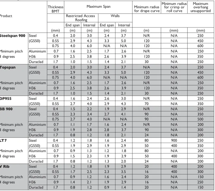
2.1.3.1 PROFILE SPAN AND CURVATURE - QUICK GUIDE TABLE 2.1H
This table is a quick reference guide on span and curvature limitations for all Dimond Roofi ng and Wall Cladding profi les. For detailed Serviceability and Ultimate Limit State design, please refer to Section 2.1.4 – Specifi c Design by Profi le Performance.
Basis to the tables:
Rooi ng – the spans are for roofs with restricted access or where the ultimate wind load capacity does not exceed 1.5 kPa. A restricted access roof is where there is occasional foot traffi c, that is educated to walk on the purlin lines, in the profi le pans, or carefully across two profi le ribs. Walkways will be installed where regular traffi c is expected and “Restricted Access” signs placed at access points.
Walls – spans are limited by acceptable appearance or an ultimate wind load of 2 kPa.
Rooi ng fasteners – average of 4 screw fasteners per sheet per purlin. Based on Hex-head screws without washers. The number of fasteners can be reduced by specifi c design (refer to Section 2.1.4 – Specifi c Profi le Performance).
Drape curve – radii are limited by acceptable roof appearance, refer to Section 2.4.2.
Crimp and roll curve – radii are limited by machine capabilities.
Overhang – for restricted access roofs. The unsupported area is not intended to be used as an access way.
February 2012
Thickness BMT
Maximum Span Minimum radius for drape curve
Minimum radius for crimp or roll curve Maximum overhang unsupported
Product Restricted Access Walls
Roofing
End span Internal End span Internal
(mm) (m) (m) (m) (m) (m) (mm) (mm)
Steelspan 900 Steel 0.4 2.0 3.0 2.4 3.7 N/R N/A 250
(G550) 0.55 2.9 4.3 3.3 5.0 120 N/A 450
0.75 4.0 6.0 N/A N/A 120 N/A 600
Minimum pitch Aluminium 0.7 1.6 2.5 1.7 2.6 N/R N/A 250
3 degrees H36 0.9 2.5 3.8 2.6 3.9 120 N/A 350
Duraclad 1.7 1.0 1.5 1.4 2.1 30 N/A 250
Topspan Steel 0.4 2.0 3.0 2.4 3.7 N/A N/A 250
(G550) 0.55 2.9 4.3 3.3 5.0 120 N/A 450
0.75 4.0 6.0 N/A N/A 120 N/A 600
Minimum pitch Aluminium 0.7 1.6 2.5 1.7 2.6 N/R N/A 250
3 degrees H36 0.9 2.5 3.8 2.6 3.9 120 N/A 350
Duraclad 1.7 1.0 1.5 1.4 2.1 30 N/A 250
BB 900 Steel 0.4 1.5 2.2 1.9 2.9 N/R N/A 250
(G550) 0.55 2.3 3.4 2.7 4.1 90 N/A 350
0.75 2.7 4.0 N/A N/A 90 N/A 500
Minimum pitch Aluminium 0.7 1.1 1.7 1.6 2.4 N/R N/A 200
3 degrees H36 0.9 1.9 2.8 2.8 3.7 90 N/A 300
Duraclad 1.7 0.8 1.2 1.8 2.1 24 N/A 200
LT7 Steel 0.4 1.2 1.8 1.6 2.4 80 900 250
(G550) 0.55 1.9 2.9 1.9 2.9 50 400 350
Minimum pitch Aluminium 0.7 0.9 1.3 1.2 1.8 80 N/A 200
3 degrees H36 0.9 1.5 2.3 1.9 2.9 50 400 300
Duraclad 1.7 0.8 1.2 1.3 2.0 24 N/A 200
V Rib Steel 0.4 1.2 1.8 1.9 2.9 20 400 200
(G550) 0.55 1.7 2.5 2.3 3.5 16 400 300
Minimum pitch Aluminium 0.7 0.9 1.2 1.6 2.4 20 N/A 150
4 degrees H36 0.9 1.4 2.1 1.9 2.9 16 N/A 250
Duraclad 1.7 0.8 1.2 0.9 1.4 20 N/A 150
DP955 Steel 0.4 1.6 2.4 2.6 3.0 N/R N/A 250
(G550) 0.55 2.7 4.0 2.9 4.3 70 N/A 350
Note: N/A = not available, N/R = not recommended, * = Roll curve only. Refer to Section 2.1.4 – Specific Design by Profile for a manufacturing locality guide for each profile.
2.1.3.1 Continued
Thickness BMT
Maximum Span Minimum radius for drape curve
Minimum radius for crimp or roll curve* Maximum overhang unsupported Roofing
Restricted Access Walls End span Internal End span Internal
(mm) (m) (m) (m) (m) (m) (mm) (mm)
Styleline Steel 0.4 1.0 1.6 1.6 2.4 80 900 200
(G550) 0.55 1.5 2.2 2.0 3 40 400 250
Min pitch 3º Aluminium 0.7 0.8 1.2 1.2 1.8 80 N/A 100
H36 0.9 1.1 1.7 1.7 2.6 40 400 200
Duraclad 1.7 0.7 1.1 1.1 1.7 12 N/A 100
VeedekTM Steel 0.4 1.0 1.6 1.6 2.4 N/R N/A 200
(G550) 0.55 1.5 2.2 2.0 3 N/R N/A 250
Min pitch 3º Aluminium 0.7 0.8 1.2 1.2 1.8 N/R N/A 100
H36 0.9 1.1 1.7 1.7 2.6 N/R N/A 200 Duraclad 1.7 0.7 1.1 1.1 1.7 N/R N/A 100 Corrugate Steel (G550) Steel (G550) 0.4 0.7 1 1.1 1.7 12 450* 100 0.55 1 1.5 1.6 2.4 10 450* 150
Min pitch 8º Aluminium 0.7 0.5 0.8 0.8 1.2 12 450* 75
H36 0.9 0.8 1.2 1.4 2.1 10 450* 150
Duraclad 1.7 0.6 0.9 0.9 1.3 8 N/A 100
Dimondek 630 Steel (G550) 0.48 2.0 3.0 1.4 2.1 250 N/A 150
0.55 2.4 3.7 1.7 2.6 250 N/A 250
Dimondek 400 Steel
(G300)
0.55 1.1 1.6 1.0 1.3 70 N/A 250
0.75 1.5 2.2 1.3 1.9 70 N/A 300
Min pitch 3º Aluminium
H36 0.9 0.9 1.3 0.7 1.0 70 N/A 200
Copper
0.55 0.9 1.4 0.7 1.1 70 N/A 200
1/2 hard
Dimondek 300 0.55 1.3 2 1.2 1.9 N/R N/A 250
Min pitch 3º 0.75 1.5 2.3 1.5 2.3 N/R N/A 350
Aluminium H36 0.9 1.1 1.6 1.0 1.5 N/R N/A 200 Copper 0.55 1.1 1.8 1.1 1.7 N/R N/A 200 1/2 hard Super Six Duraclad 1.7 1 1.2 1.8 2 28 N/A 250 Min pitch 3º Dimondclad Steel (G550) Steel (G550) 0.4 N/R N/R 0.9 1.4 N/R N/A 100 Aluminium 0.7 N/R N/R 0.9 1.4 N/R N/A 75 H36 0.9 N/R N/R 0.9 1.4 N/R N/A 100
Baby Corrugate Steel 0.4 N/R N/R 0.4 0.6 N/R N/A 75
(G550) 0.55 N/R N/R 0.4 0.8 N/R N/A 75
Wall cladding only Wall cladding only
Wall cladding only
Fineline 0.55 N/R N/R 0.3 0.3 N/R N/A N/R Aluminium 0.9 N/R N/R 0.3 0.3 N/R N/A N/R H36
Note: N/A = not available, N/R = not recommended, * = Roll curve only. Refer to Section 2.1.4 – Specific Design by Profile for a manufacturing locality guide for each profile.
December 2012
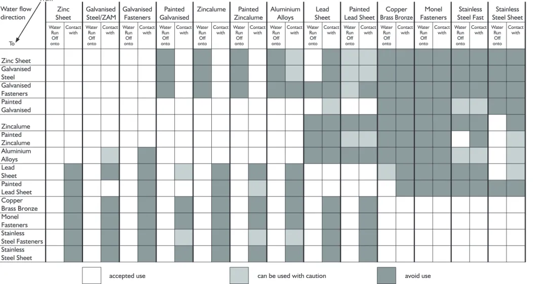
Corrosion from dissimilar materials usage may have two origins:
• Contact between different metals, producing a galvanic cell which causes the more active metal to corrode. • Water run-off from particular materials on to a metal, causing corrosion.
Surface oxide, relative surface areas, water purity and environmental factors can inluence the outcome, so the consequences may not relate strictly to the well-publicised Galvanic Series.
Table 2.1I shows which metals and materials can be used together in a roof and/or gutter installation and which should be avoided.
If dissimilar metal usage cannot be avoided then contact and/or water run-off must be avoided by insulating surfaces. Separation by rubber seal or coating the surfaces and maintaining the coating as an effective barrier for the life of the roof will be required. For further important information refer to the MRM code of practice www.metalrooing.org.nz.
Contact with non-metal materials and water run-off from them can also cause corrosion problems. Well-known examples are:
• Inert catchment - where water running from a non-zinc surface onto unpainted galvanised steel can cause rapid consumption of galvanising. The guilty surfaces include glass, plastic including GRP sheeting, painted or unpainted Zincalume®, painted galvanised steel, concrete tiles and butyl rubber. (The effect is often seen
on the unpainted interior surface of galvanised gutters where rust spots will appear at each water drip point).
• Timber - particularly copper treated including treated timber walkways. Any contact with wet timber should be avoided.
• Lime cement and concrete. • Wet insulation.
• Soot or sulphur.
• Carbon (lead pencil or some black sealing washers), which causes Zincalume® to corrode.
• Netting must be used under aluminium rooing, where galvanised netting has not been correctly isolated and has made contact with the Aluminium roof underside, piting of the aluminium will occur. Either avoid using galvanised netting or isolate contact with inert strip such as a Dimond purlin protection strip or install over a vented drainage mat. Building paper can not be relied on as an inert strip especially in severe marine environments.
• When stainless steel ixings are used through aluminium roofs a clearance hole around the ixing and a proiled washer and EPDM seal have not been used, any moisture especially salt laiden air creates a corrosive cell between the stainless steel and the Aluminium which results in rapid corrosion of the Aluminium. Clouts or staples are another good example to avoid when in contact with aluminium roofs. • Alternatively an aluminium ixing could be used into non copper treated timber, in place of the stainless steel. Table 2.11 Dissimilar Metals Guide - Overleaf
June 2013
2.1.3.3 DISSIMILAR MATERIALS
R
oofi
ng and W
all Cladding Systems P
erformance Zinc Sheet Galvanised Steel Galvanised Fasteners Painted Galvanised Zincalume Painted Zincalume Aluminium Alloys Lead Sheet Painted Lead Sheet Copper Brass Bronze Monel Fasteners Stainless Steel Fasteners Stainless Steel Sheet Zinc Sheet Galvanised Steel/ZAM Galvanised Fasteners Painted Galvanised Zincalume Painted Zincalume Aluminium Alloys Lead Sheet Painted Lead Sheet Copper Brass Bronze Monel Fasteners Stainless Steel Fast Stainless Steel Sheet Water Run Off onto Contact with Water Run Off onto Contact with Water Run Off onto Contact with Water Run Off onto Contact with Water Run Off onto Contact with Water Run Off onto Contact with Water Run Off onto Contact with Water Run Off onto Contact with Water Run Off onto Contact with Water Run Off onto Contact with Water Run Off onto Contact with Water Run Off onto Contact with Water Run Off onto Contact with e s u d i o v a n o i t u a c h t i w d e s u e b n a c e s u d e t p e c c a Water fl ow direction To From 2.1.3.3 Continued
Table 2.11 Dissimilar Metals Guide
Example – Zincalume: to check the compatibility of Zincalume with other material, locate Zincalume along the top (horizontal axis) and check the water run-off and contact columns for compatibility with other materials. This indicates, for example, that water run-off from Zincalume onto unpainted galvanised steel must be avoided, but that direct contact between Zincalume and galvanised steel is acceptable.
May 2006
2.3.1 HANDLING AND STORAGE
Correct handling of profiled metal roofing and cladding products is critical to ensure damage does not occur during transportation and storage of the material. The following comments are made as guidelines to be used when inspecting Dimond Roofing and Wall Cladding Systems during the installation process.
Visual inspection of materials when they are delivered to the site should be carried out to ensure they are dry and free from damage. All components stored on site must be kept dry.
Site storage of sheet material requires dunnage evenly spaced to provide a surface for the materials to be placed on that is in plane.
Covers must be placed over the material to ensure it does not become wet during any storage period, and must remain clear of the material surface so air can circulate freely around the bundle. Product with strippable film applied must not be exposed to direct sunlight during storage.
The need to keep the sheets dry applies to all metal types. If aluminium is stored wet it will suffer black staining that detracts from appearance. If pre-painted Zincalume® products are stored wet, the paint finish will blister due to moisture absorption and eventual under-film corrosion. If unpainted Zincalume® products are stored wet, the surface will stain and can suffer loss of protection that will show up in time as premature corrosion. If the sheets have remained in this wet condition for more than 3 days, they should not be used. If sheets do become wet and remained wet for less than 3 days, they must first be removed from the stack, immediately dried thoroughly and re-stacked with timber fillets being placed evenly between the sheets to ensure air can circulate freely over the sheet surfaces.
Sheets must always be lifted clear of the stack, never dragged.
Adequate support must be given along the length of sheets when lifting, whether it be single sheets by hand or bundles of sheets by crane or other lifting device. When lifting by mechanical means, spreader bars must be used to ensure the fabric strops do not damage the edge of the sheets as they are lifted.
The following comments are made as guidelines to be used when inspecting Dimond Roofing and Wall Cladding Systems during and after installation.
a.Netting
Netting should be run across purlins and tensioned to remove unnecessary sag. Fastening to timber should be with either galvanised staples or 25mm clouts avoiding contact with the roofing, and to steel with flat head screws. Fixings should be at 150mm centres on end purlins in such a way that the netting cannot pull past the fixing. Edges of the netting should be tied together or twitched at 300mm centres and fixed to each purlin. Safety mesh should be installed to safety mesh manufacturers recommendations.
b. Roofing Underlay
Horizontal Application: underlay is unrolled across the roof parallel with purlins and secured as necessary. Joins should be lapped by a minimum of 75mm and supported on netting if roof pitch is below 8 degrees for self supporting and have the side edges supported on purlins.
Vertical Application: underlay is unrolled vertically up the slope of the roof from guttering to ridge and secured to the purlins as necessary before laying the roof sheet and fixing down. Joins should be lapped by a minimum of 150mm. Supports such as netting or safety mesh must be used on pitches below 8 degrees, or when using self supporting underlays on purlin spacings greater than 1200mm.
When used under roofing, all underlays must be supported on wire netting or strapping at 300mm maximum spacings. Self sufficient underlays can be used on purlins spacing up to 1200mm without support.
Underlay should overlay into the gutter at least 20mm and not more than 50mm, and avoid lapping into the water flow. Maximum single underlay sheet lengths shall be 10m for bituminous and fire retarded kraft papers. Longer runs are to be end lapped 150mm. Synthetic underlays have no limit on their run length.
In general it is recommended that prolonged exposure of the underlay to the weather is avoided by fixing the roofing over the same day. Always follow underlay manufacturers recommendations.
c. Roofing and Cladding Sheets Supporting Structure
• Rooing and wall cladding sheets should not be installed until the rooing contractor is satisied that the
support structure is complete, sound, and correctly aligned. This includes support around penetrations and openings.
• Purlin and girt spans both end and internal spacings must be in accordance with Dimond recommendations for
profile, metal type and thickness, as well as the expected level of foot traffic. If in doubt, check.
• Curved roofs(whether draped/rolled or crimped) require purlin alignment within ±5mm to minimise the risk
of unacceptable finished appearance.
• Spacers must be ixed to steel purlins to allow insulation to it between and to create a 25mm air gap between
underlay and insulation. Do not compress the insulation.
Where the building is under the scope of E2/ASI there is a requirement to install horizontal wall cladding onto
a cavity batten system to achieve a 20mm air space between the back of the cladding and wall framing on all
walls in accordance with NZBC E2/ASI. Dimond proiles that come within the scope of E2/ASI are: Corrugate,
Styleline, VeedekTM, DD300, DD400 and V-Rib.
Vertical run cladding does not require a cavity batten system on any risk matrix wall provided the details and
installation is carried out in accordance with recommendations in this manual, which are based on past history where Dimond profiles have successfully been fixed.
Installation in this way will not be in accordance with E2/ASI: June 05 and is an alternative solution.
Continued on next page ...
June 2013
2.3.2 LAYOUT AND FASTENING
June 2013
2.3.2 Continued Sheet Layout
• Firstly, the sheet should show no signs or evidence of transport damage or storage damage including wet storage effects. If the sheets are damaged they must not be fi xed down, and the Dimond supplying branch should be informed as soon as possible.
• Care should be taken to ensure sheets are laid parallel to the lines of building ends, and perpendicular to ridges and gutters. If possible, the direction of laying should be such that the sheet side laps face away from the prevailing wind direction, or, in the case of wall cladding, away from the most common line of sight.
• Side laps must be properly engaged such that the overlap rib fi ts correctly over the underlay without obvious gaps or insuffi cient cover.
• Roofi ng sheets should run continuously from ridge to gutter, avoiding end laps. Long lengths separated for thermal expansion or handling reasons should join at a step in the roof. Where end lapping of straight and curved sheets cannot be avoided, a correctly formed 150mm minimum sealed lap is required, with a bead of neutral curing silicone sealant each end of the lapped sheets.
• Sheet ends should form an even line (within a workable tolerance) and roof sheeting should overhang into gutters by at least 50mm and must allow clearance to enable ease of gutter cleaning.
Sheet Ends
• All roofi ng and wall cladding sheet ends that terminate under fl ashings (regardless of pitch) should be
formed with a full vertical dog-eared stop end to the full height of the profi le rib. Where a full height dog-eared stop end cannot be achieved, a pull up stop end a minimum 28mm high on all profi les excluding Corrugate must be provided in conjunction with foam profi le closures.
• For roofs below 8 degrees pitch the drip edge sheet end should be formed with a down turned lip. Sheet Fastening
• Sheet must be fastened to every purlin (or girt) to transfer outward loads evenly to every structural member. • The fastener system used should meet specifi cation requirements and have a durability to at least match that
of the sheeting, and be in accordance with Dimond literature for that profi le.
• Fasteners must be perpendicular to the sheeting and tightened suffi ciently to effect a durable seal without over tightening that results in seal washer distortion or profi le crest dishing and depressing. Fixings must be to a line.
• Concealed clips used to fasten Dimondek 300, Dimondek 400 and Dimondek 630 products should not exhibit screw or nail head protrusion such that damage to the roof sheet and coating may result.
• Whenever oversize holes are required to accommodate expansion, profi led washers and seals must be used. • Profi led washers and seals should be used whenever specifi ed to provide extra wind uplift capacity.
• Note should be made to ensure there are suffi cient fasteners, evenly distributed. In particular the perimeter zones of roofs, where maximum wind uplift occurs, must have suffi cient fasteners.
• No areas on the roof should hold water that will cause ponding long term. The structure may require realignment and if the profi le is damaged, this should be replaced.
Wall Cladding Underlay
• Can be laid either horizontally on steel girts or vertically on timber studs.
• When run horizontally lap upper sheet over lower sheet a minimum of 75mm. Adequately secure to framing at 300mm centres. When installed in high wind areas fi x through a reinforced tape such as Danband branded polypropylene tape.
• Run lengths to be no greater than 10m.
• End laps to be no less than 150mm over studs of vertical joints. • The underlay should be pulled taut as possible.
• Best practise is to Clad on the same day as the installation provided the product is kept dry and undamaged.
Continued on next page... Installation Information
• Maximum period that the underlays are exposed to the weather is contained in Underlays manufacture literature.
June 2013
2.3.2. Continued Side Lap Fastening
Steel
All metal profi les must have side laps fastened (either by primary fasteners through to the purlins, or by stitching the top sheet to the underlay sheet) to comply with the following maximum spacings.
Material Thickness (mm) Maximum Side Lap Fastener Spacing (mm)
Rib height 30mm or less Duraclad (GRP)
Rib height greater than 30mm
Wall Cladding Side Lap
Side lap stitching on pan fi xed wall cladding is recommended to improve the lap weather tightness, when the distance between fi xings is greater than 1.5m. Side lap fi xings should not exceed 750mm centre to centre. The recommended side-lap fasteners for stitching sheets together are:
Metal Sheeting
10 – 16 x 16mm Hex head Tek® screws 10 – 12 x 20mm Hex head Type 17 screws Duraclad
Bulb - Tite Rivet
or Bolt and compressible rubber sleeve d. Duraclad
The above comments for roofi ng and cladding sheets generally apply. Additional attention should be given to: • S topendsshouldbecorrectlyformedbyattachingameta l(usuallyaluminium)foldedangletothesheetend,
and sealing it in place.
• The supporting structure must be free of abrasive surfaces or irregularities. If used over netting or safety mesh, a barrier strip must be installed to prevent abrasive damage to the sheet surface.
• Fastening of Duraclad requires pre-drilling of the sheet with a hole size that is at least 2mm greater than the fastener diameter. Additional hole size may be required to accommodate thermal expansion of the sheeting. • 32mm Weatherlok washers must be used as specifi ed.
• Provision should be made during installation to enable foot traffi c movement across the roof without applying point loads to the Duraclad sheeting. Planks or temporary walkways are recommended.
• Safety Mesh must be installed underneath Duraclad if the sheet thickness is less than 1.7mm. (If general foot traffi c is expected, consult Dimond for the use of products specifi cally designed for the purpose.)
e. Natural Lighting Products
Refer to Section 2.4.1.3 for installation of these products.
Installation Information 0.40 0.55 0.75 1500 2000 2400 Aluminium 0.70 0.90 1500 2000 1.7 1.7 Duraclad (GRP) 750 1000
May 2006
2.3.3 FLASHINGS / PENETRATIONS
The following comments are made as guidelines to be used when inspecting Dimond Roofing and Wall Cladding Systems during and after installation.
Material
Must be the same material and coating as the roof or wall cladding to give a similar durability and compatibility as the roof/wall system.
Fabrication
Flashings should be fabricated to achieve sufficient cover width and to maintain falls to avoid water ponding. They must be without noticeable micro-cracking and be fixed without damage such as dings or crushing, and should be free of scratches and swarf the same as for roofing.
Flashing joins must be sealed at both ends of the lap, and the fasteners must pass through the sealant at the leading edge. Spacing of fasteners should be no greater than 50mm apart. Laps to be 150mm min.
Fastening
Wherever possible, flashings should be screw fixed through to the supporting structure, with sufficient slope or fall to ensure ponding does not occur. Stitch screws should be the preferred means of attaching flashings to sheeting ribs. If aluminium rivets are used, the minimum size should be 4.8mm diameter.
All fasteners should be of sufficient size and frequency to withstand the loads that may be applied through wind uplift or thermal expansion, throughout the life of the roofing material. As a guide, where flashings cover the roof, use the same fastener that has been used to fasten the roof.
As a guide, the fastener frequency for fixing flashings should be: Wind Zone* Fasteners Per Metre
Low (32 m/s) 1
Medium (37 m/s) 2
High (44 m/s) 3
Severe (50 m/s) 4
*in accordance with NZS 3604
Sensible allowance should be made to allow relative thermal expansion between flashings and sheeting if sheet lengths exceed 12m.
Expansion joints in the flashings should be considered for steel flashings greater than 18m and aluminium flashings greater than 12m in length.
Flashing lapping over roofing should be in accordance with Table 2.1.O of Section 2.1.3.6 in this manual. Where barges meet the gutter, this must be closed off to ensure wind driven moisture and birds cannot enter the building.
June 2013
2.3.3 Continued Profiled Foam
Profi led foam sealing strips should be installed when specifi ed at the top end of the sheet, adjacent to the stop end. To help keep the strips in place it is good practice to position them on a bead of silicone sealant. Notching
Best practice to notch fl ashing downturns around sheet profi les is to mark in-situ and use a rib-shaped template. Clearance gaps around the rib should be just suffi cient to prevent cut edge contact with the sheet surface. Gaps between 1mm and 3mm are generally considered satisfactory.
Soft edging can be used on corrugate and low rib profi les with rib heights up to 30mm and should be neatly pushed down and formed in to the profi le pans to achieve a neat-tight fi t.
Property boot pipe flashing
Property boot pipe flashings must not be positioned in such a way that a dam is formed across a water channel. It is preferred that Property boot pipe flashings are positioned on the ‘bias’ rather than square across the sheet. If the
pipe and Property boot pipe flashing dam up the pan or restrict more than 50% of the water flow around the pipe and flashing, an additional cover over flashing to the ridge and sealing of the Property boot pipe flashing to this flashing should be considered. Excess silicone sealant should be avoided, as it will add to the risk of water ponding Penetrations
Penetration holes with their major dimension or diameter greater than 150mm must have support framing placed around the perimeter of the penetration holes.
Water diversion around the penetration must not cause an overload of the receiving channel such as the pans that the water has been diverted into, which may cause fl ooding. Penetration fl ashing shall not rely solely on the silicone sealant to achieve weather tightness of the fl ashing.
May 2006
2.1.3.6 Continued
Table 2.1.O Effective Minimum Cover of Flashing Over Roof Sheet (mm)
Flashing Type Ridge
– transverse over roofing 130 200
Barge
– parallel with ribs 1 rib 2 ribs
– parallel with corrugate 2 corrugations 3 corrugations
– vertically down smooth face sheet 50 75
– vertically down profiled face sheet 75 100
Apron
– transverse over roofing 130 200
– parallel with ribs 1 rib 2 ribs
– parallel with corrugate 2 corrugations 3 corrugations
– vertically up smooth face sheet 50 + hem or 75 75 + hem or 100
– vertically up profiled face sheet 75 + hem or 100 100 + hem or 125 Parapet
– vertically down smooth face sheet 50 75
– vertically down profiled face sheet 75 100
Notes:
Dimension excludes any soft edge or turn down to roofing.
Wall cladding must finish within 25mm above any apron flashing to allow clearance and avoid dirt building up. In high wind areas a profiled foam seal can be used under the ridge or apron flashing, over the roofing, to create a pressure differential chamber to avoid moisture being driven in. The foam seal should be placed adjacent to the stop end at the head of sheet.
All roof and wall cladding profiles are to be stop ended at the top end of the sheet on all pitches.
The cover dimensions given above are the cover over the roof or wall cladding not the leg length of the flashing. On profiles other than Corrugate where cover over 2 ribs is required, flashings must cover at least one rib plus the trimmed side of the sheet turned up to the full height of the rib.
Roofing and Wall Cladding Systems Performance
For all pitches in very high wind zones and for all wind zones
roof pitch is 10º or greater Low, medium or high wind
zones where roof pitch is less than 10º
The following comments can be used as guidelines to be used when inspecting Dimond Roofing and Wall Cladding Systems during and after installation.
Roof Access
The means of access must be safe and secure, and should provide protection to the sheeting at the access point. Provision for cleaning or changing footwear to prevent the transfer of dirt onto the roof surface is recommended to minimise the risk of surface scratching damage.
Walking on Roofs
Soft, clean (free from dirt and clay) light coloured sole footwear must be worn. Foot placement should be close to purlin lines, and point loads should not be applied to profile ribs through careless weight distribution while walking. Avoid foot placement on the underlay edge of roof sheets.
Translucent or Natural Lighting sheet must not be walked on. Subsequent Trades
The work habits of trades accessing the roof must be controlled to avoid unnecessary damage from foot traffic, swarf, and storage of materials. Installed roofing that will be subject to further use (or abuse) during building construction should be protected by covers or temporary walkways. Care must be taken to
protect and avoid scratching of the paint finish. The placement of scaffolding legs onto a roof should be avoided unless there is adequate support and protection to the roof finish to avoid damage. Penetration flashing should be placed as close to the ridge as possible to avoid large catchment areas upstream of the penetration. All penetration flashings should be done in accordance with the MRM Roofing Code of Practise.
Dissimilar Materials
Care should be taken to ensure that incompatible materials have not been used, particularly through the installation of walkways and air conditioning equipment. Copper pipe must not discharge or allow water run-off onto the metal roof. Where necessary, water run-off from dissimilar metals should be contained and discharged separately from the roofing material.
Wall cladding lapping onto concrete tilt slab or block walls must not contact the concrete. A small gap, such as 5mm, between or isolation strip is recommended.
Drilling and Cutting
When metal sheets require cutting, only shears, powered nibblers or hand snips should be used to leave a cleanly cut sheared edge. Any form of disc cut will nullify the material warranty.
Cutting of Duraclad sheets can be with an abrasive disc or a fine tooth saw. Breathing protection should be worn to prevent inhalation of dust.
Cutting and drilling should be carried out clear of other sheeting material, and the drilling swarf immediately removed from the surrounding sheet surface.
Coil on cut edge protection lacquer may be required to be painted on all cut edges in severe marine area to meet warranty requirements. Check with Dimond.
Swarf
The particles of metal that result from cutting, drilling or self-drilling screw placement can adhere to the sheet surface and rapidly corrode, causing staining problems. The sheet durability is not affected provided the swarf particles have not penetrated the coating. Loose swarf must be removed without damage to the metal surface at least at the end of each day’s work including swarf driven by wind up under barge or apron flashings. Remaining adhered swarf may be best left alone, provided no particles have broken the coating surface and the visual effect is acceptable. Roofs with heavy deposits of swarf or where the coating has been broken may require the affected sheets to be replaced.
It is best trade practice to clean up after each day’s work to avoid swarf damage.
June 2013
June 2013
2.3.4 Continued General Appearance
Screw fasteners should be installed to a straight line (staggered for lapped purlins). Extra care on wall cladding is required to achieve this. Flashings should run parallel with profi le ribs or the building line.
Sheet side laps should not exhibit excessive gaps, which can be controlled by careful sheet layout and side lap stitching if necessary.
Water Ponding
The installed roof and fl ashings must not exhibit water ponding. Buckling of profi le pans caused by poorly formed lip downturns at gutter lines is a particular area of potential ponding that should be checked. Sealants
Only neutral cure silicone sealants should be used. All sealed joints must be mechanically fastened, and excess sealant removed to prevent unnecessary dirt buildup.
Joints in fl ashings or roof plane intersections should not be constructed in a way that relies entirely on sealant to remain weather secure. Sealant should only be used to seal between two metal surfaces, not fi ll holes or gaps. Cleaning on Completion
All forms of debris must be removed daily from the roof surface to prevent scratching damage and moisture or dirt retention. On completion the roof should be thoroughly washed down and then inspected for any damage and any necessary remedial work carried out.
Strippable Film
Protective fi lms must be removed within 1 day of product installation. Prolonged UV exposure will make removal diffi cult. The fi lm must be removed from laps and under fl ashings during installation.
Scratches and Touch-up
Scratches that have not penetrated to the base metal (on coated materials) and minor surface abrasions should be left alone, as touch up painting will become obvious in time.
Sheets with heavy scratch damage (e.g.: scratches readily visible from a 3-metre distance that expose the base metal) should be replaced.
Buckled Ribs
Minor buckles that have occurred in profi le ribs and will not retain water can be left alone. More severe buckles that will retain water or weaken the sheet should be pushed out from underneath, or be capped over with a rib section extending a minimum 50mm beyond the damaged section, fully sealed with silicone sealant and held onto the roofi ng rib with 4mm diameter blind aluminium rivets each side.
Major buckles that affect more than 1/4 of the ribs in line across any sheet will cause a severe loss of strength, and in such cases the sheet must be replaced, ie if more than 2 adjacent ribs are buckled on the same purlin line, the sheet’s ability to hold load is reduced and it must be replaced.
For online technical information
visit the Architects section at www.dimond.co.nz
Contact your Dimond Sales Centre:
0800 DIMOND (0800 346663)
For Sales, Delivery, Availability & Pricing Information
Specific Design by Profile
2.1.4.1 Dimond Steelspan 900 & Topspan 2.1.4.2 Dimond Brownbuilt 900 (BB900) 2.1.4.3 Dimond LT7
2.1.4.4 Dimond V-Rib
2.1.4.5 Dimond Styleline & VeedekTM
2.1.4.8 Dimond Corrugate 2.1.4.15 Dimondek 630 2.1.4.9 Dimondek 400 2.1.4.10 Dimondek 300
2.1.4.12 Dimondclad Rib 20 & Rib 50 2.1.4.13 Dimond Baby Corrugate
ROOFING AND
WALL CLADDING
SYSTEMS GUIDE
THE WAY TO INSPIRED
DESIGN CHOICES…
DIMOND ROOF, WALL AND
GUTTER SYSTEMS
RAIN W A T E R S Y S T E M S M E T A L T ILE SYS T E M S N A T U R A L LIGH T ING & C U R V ED ROOFING SYSTEM S SPECIFIC DESIGN B Y PROFIL E ROOFING & W A LL CLADDING SYSTEM S 2.1.4.18 Dimond DP955Roofing and Wall Cladding Systems Performance
January 2010
2.1.4.1 (a) DIMOND STEELSPAN 900 AND TOPSPAN PROFILE PERFORMANCE
Cover (mm) 900
Sheet width (mm) 970 All dimensions given are nominal
Minimum Pitch 3º (approx. 1:20)
Sheet Tolerances
4IFFUXJEUIßNN
Sheet width for aluminium +0, –15. If sheet cover widths are critical, advise Dimond at time of order. Sheet length: +10mm, –0mm. For horizontal wall cladding where notified at time of order of intended use, tighter tolerances can be achieved +3mm, –0mm.
Material Options Steel Aluminium Duraclad
Thickness (BMT) mm 0.4 0.55 0.75 0.7 0.9 1.7 (total thickness)
Nominal weight/lineal metre (kg/m) 4.12 5.55 7.47 2.31 2.96 2.70
Drape curved roof – min. radius (m) n/r 120 120 n/r 120 30
Purlin spacings for drape curved roof (m) (1) n/r 2.4 2.4 n/r 2.4 1.5
Machine crimp curved – roof min. radius (mm) n/a n/a n/a n/a n/a n/a
Unsupported overhang (2) 250 450 600 250 350 250
(1) Recommended maximum purlin spacing at minimum radius
(2) Based on 1.1kN point load support, but not intended for roof access. n/r – not recommended
n/a – not available
Roll-forming facility at: Auckland – Steelspan 900 Christchurch – Topspan Manufacturing location for Duraclad: Auckland
Sheet lengths: Steelspan 900 and Topspan are custom run to order. Where long sheets are used consideration must be given to:
– special transportation licences for sheet lengths over 25m – site access for special lifting equipment
– fixing techniques to accommodate thermal expansion. Refer Section 2.1.3.4. Steelspan 900 Topspan
Roofing and Wall Cladding Systems Performance
January 2010
2.1.4.1 (b) Continued
STEELSPAN 900 AND TOPSPAN LIMIT STATE LOAD / SPAN CAPACITY CHART
(span in mm, distributed serviceability and ultimate loads in kPa)
Serviceability Category
Notes
1. In any category, spans above the maximum shown should not be used. Category 1 and 2 maximum spans are based on static point load testing as a guide, and further limited by practical experience of roof performance under dynamic foot traffic loads. Category 3 maximum spans are limited as a guide to achieving satisfactory appearance for wall cladding.
2. Loads given are based on 4 screw fasteners/sheet/purlin.
3. Loads given are limited to a maximum of 4.5 kPa. If design requirements exceed this limit, contact Dimond for specific advice. 4. Duraclad
– Serviceability Limit State loads are not applicable to the Duraclad material, as it does not experience permanent deformation. – System must include Safety Mesh if intended for use as a Restricted-Access roof. Refer Section 2.2.1.8.
5. N/R = not recommended.
6. End span capacities given in this table are based on the end span being 2/3 of the internal span. 7. Design Criteria for Limit State Capacities
a) Serviceability Limit State
No deflection or permanent distortion that would cause unacceptable appearance, side lap leakage or water ponding, due to foot traffic point loads, inward or outward wind loads or snow loads.
b) Ultimate Limit State
No pull through of fixings or fastener withdrawal resulting in sheet detachment due to wind up-lift (outward) loads. System Design
The span capacity of Steelspan 900 and Topspan are determined from the Steelspan 900 and Topspan Limit State Load / Span Capacity Chart using the sections of the Chart appropriate to the grade and type of material, and to the category of serviceability selected from the three categories below. It is recommended that to obtain a dependable design strength capacity for the ultimate limit state, a reduction factor of = 0.8 is applied. The capacities given do not apply for cyclonic wind conditions.
Serviceability Requirements
While these categories are given for design guidance to meet the serviceability limit state criteria, foot traffic point load damage may still occur if there is careless placement of these point loads.
Service Category Description
1. Unrestricted-access roof Expect regular foot traffic to access the roof for maintenance work and able to walk anywhere on the roof. No congregation of foot traffic expected.
2. Restricted-access roof Expect occasional foot traffic educated to walk only on the purlin lines, in the profile pans, or carefully across two profile ribs. Walkways installed where regular traffic is expected, and “Restricted Access” signs placed at access points.
3. Non-access roof or wall Walls or roofs where no foot traffic access is possible or permitted. If necessary, “No Roof Access” signs used.
Continued on next page...
3. Non-Access Roof or Wall
2. Restricted-Access Roof 1. Unrestricted-Access Roof End Span 1200 1300 1500 1800 2000 2200 2300 2400 Internal Span 1800 2000 2200 2700 3000 3300 3500 3700 G550 Steel 0.40mm Serviceability Ultimate 3.4 4.5 2.7 4.5 2.6 4.5 2.0 4.0 1.6 3.2 1.5 3.0 1.3 2.6 1.2 2.4 End Span 2000 2300 2400 2900 3300 3400 3600 Internal Span 3000 3500 3600 4300 5000 5100 5500 G550 Steel 0.55mm Serviceability Ultimate 2.3 4.5 1.8 3.9 1.7 3.7 1.3 2.8 1.0 2.2 0.9 1.9 0.6 1.1 End Span 2800 2900 3400 4000 4100 4300 Internal Span 4200 4400 5200 6000 6200 6600 G550 Steel 0.75mm Serviceability Ultimate (See note 6) (See note 6) 2.3 2.5 2.2 2.4 1.8 2.0 1.5 1.8 1.3 1.7 1.1 1.6 End Span 1100 1200 1400 1600 1700 Internal Span 1700 1800 2100 2500 2600 5052, H36 Aluminium 0.70mm Serviceability Ultimate 2.6 4.3 2.4 4.2 2.0 3.8 1.6 2.8 1.4 2.5 End Span 1700 1800 2100 2500 2600 Internal Span 2600 2700 3200 3800 3900 5052, H36 Aluminium 0.90mm Serviceability Ultimate 2.2 3.4 2.0 3.1 1.5 2.9 1.2 2.4 1.0 2.0 End Span 900 1000 1100 1300 Internal Span 1500 1600 1900 2200 Duraclad 1.7mm (Note 4) Serviceability Ultimate N/R N/R - 4.4 -3.6 -2.4 -1.8 1500
Roofi ng and Wall Cladding Systems Performance
June 2013
2.1.4.1 (b) Continued Fastener Design
Steelspan 900 and Topspan should be screw fi xed to either timber or steel purlins. The use of the appropriate length of 14g roofi ng screw will ensure failure by screw pull out will not occur under loads within the scope of the Limit State Load / Roofi ng Span Capacity Chart.
Roofi ng Rib Wall Cladding Pan Screw Length* Designation Screw Length* Designation
(mm) (mm)
Timber 100 T17 – 14 – 10 x 100 50 Roofzip
M6 x 50 HG-Z4 Steel 95 Tek – 14 – 10 x 95 20 Tek – 12 – 14 x 20
* If sarking or insulation is used over the purlins or for wall cladding fi xing onto a cavity batten, into the stud, the screw length will need to be increased.
For screw size range and fastener / washer assembly refer Section 2.2.3.1.
The Limit State Load / Span Capacity Chart is based on 4 screw fasteners/sheet/purlin without the use of load spreading washers (except for 0.4mm steel, 0.7mm aluminium and Duraclad material, which must be fi tted with either profi led metal washers and 36mm EPDM seals, or 32mm Weatherlok washers for Duraclad only).
Profi led metal washers are recommended for use:
1. On end spans, or large internal spans where the Ultimate Limit State distributed load is limiting. Contact Dimond for specifi c advice in these design cases.
2. When required to enable the fi xing system to accommodate the thermal movement of long sheets – see Section 2.1.3.4 Thermal Movement.
3. Wherever the designer wishes to ensure the risk of fastener over-tightening will not cause dishing of the crest of the profi le rib.
Use in serviceability categories (1) or (2) can allow the reduction of fasteners to 2 screw fasteners/sheet/purlin by using 2 fasteners/sheet/purlin. If this is done, the distributed load capacities given in the chart should be reduced using a multiplying factor of 0.5.
Long spans may require the specifi cation and use of side lap stitching screws – see Section 2.3.2C Installation Information: Layout and Fastening.
Design Example
Restricted access roof, 0.55mm G550 steel Steelspan 900 has a maximum end span of 2900mm and a maximum internal span of 4300mm. The following distributed load capacities apply.
End Span 2900mm 2900mm
Internal Span 4300mm 4300mm
Serviceability 1.3 kPa 0.6 kPa
Ultimate 2.8 kPa 1.4 kPa
Continued on next page... Screw Fastener
Purlin Type
Roofing and Wall Cladding Systems Performance
2.1.4.1 (b) Continued
DIMOND STEELSPAN 900 AND TOPSPAN
FASTENER LAYOUT OPTIONS
June 2008
4 fasteners/sheet
sheet end
2 fasteners/sheet
Roofi ng and Wall Cladding Systems Performance
February 2012
2.1.4.18 (a) DIMOND DP955 PROFILE PERFORMANCE
Cover (mm) 955
Sheet width (mm) 1020 All dimensions given are nominal Minimum Pitch 3º (approx. 1:20)
Sheet Tolerances
Sheet width: ±5mm
Sheet length: +10mm, –0mm. For horizontal wall cladding where notifi ed at time of order of intended use, tighter tolerances can be achieved +3mm, –0mm.
Material Options Steel
Thickness (BMT) mm 0.4 0.55
Nominal weight/lineal metre (kg/m) 4.12 5.55 Drape curved roof – min. radius (m) n/r 70 Purlin spacings for drape curved roof (m) (1) n/r 2.7 Machine crimp curved – roof min. radius (mm) n/a n/a
Unsupported overhang (2) 250 350
(1) Recommended maximum purlin spacing at minimum radius
(2) Based on 1.1kN point load support, but not intended for roof access. n/r – not recommended
n/a – not available Notes:
1. Where purlin spacings for roofi ng exceed 1.5m for 0.4m or 2m for 0.55m, the side lap must be fastened in accordance with Section 2.3.2.
2. When notching fl ashings around the DP955 rib, use straight cuts rather than follow the curve rib shape. Roll-forming facility at: Auckland and will be available in Christchurch from May 2012.
Sheet lengths: DP955 is custom run to order. Where long sheets are used consideration must be given to:
– special transportation licences for sheet lengths over 25m – site access for special lifting equipment
– fi xing techniques to accommodate thermal expansion. Refer Section 2.1.3.4. 46 21 955 239 80 318
Roofi ng and Wall Cladding Systems Performance
January 2010
2.1.4.18 (b) Continued
DP955 LIMIT STATE LOAD / SPAN CAPACITY CHART
(span in mm, distributed serviceability and ultimate loads in kPa) Serviceability CategoryNotes
1. In any category, spans above the maximum shown should not be used. Category 1 and 2 maximum spans are based on static point load testing as a guide, and further limited by practical experience of roof performance under dynamic foot traffi c loads. Category 3 maximum spans are limited as a guide to achieving satisfactory appearance for wall cladding.
2. Loads given are based on 3 screw fasteners/sheet/purlin with load spreading washers.
3. Loads given are limited to a maximum of 4.5 kPa. If design requirements exceed this limit, contact Dimond for specifi c advice. 4. End span capacities given in this table are based on the end span being 2/3 of the internal span.
5. Design Criteria for Limit State Capacities a) Serviceability Limit State
No defl ection or permanent distortion that would cause unacceptable appearance, side lap leakage or water ponding, due to foot traffi c point loads, inward or outward wind loads or snow loads.
b) Ultimate Limit State
No pull through of fi xings or fastener withdrawal resulting in sheet detachment due to wind up-lift (outward) loads. System Design
It is recommended that to obtain a dependable design strength capacity for the ultimate limit state, a reduction factor of = 0.8 is applied.
Serviceability Requirements
While these categories are given for design guidance to meet the serviceability limit state criteria, foot traffi c point load damage may still occur if there is careless placement of these point loads.
Service Category Description
1. Unrestricted-access roof Expect regular foot traffi c to access the roof for maintenance work and able to walk anywhere on the roof. No congregation of foot traffi c expected.
2. Restricted-access roof Expect occasional foot traffi c educated to walk only on the purlin lines, in the profi le pans, or carefully across two profi le ribs. Walkways installed where regular traffi c is expected, and “Restricted Access” signs placed at access points.
3. Non-access roof or wall Walls or roofs where no foot traffi c access is possible or permitted. If necessary, “No Roof Access” signs used.
Continued on next page...
3. Non-Access Roof or Wall
2. Restricted-Access Roof 1. Unrestricted-Access Roof End Span 800 1100 1300 1600 1800 2000 0 0 0 3 0 0 7 2 0 0 4 2 0 0 0 2 0 0 7 1 0 0 4 1 n a p S l a n r e t n I G550 Steel 0.40mm Serviceability Ultimate 2.3 4.5 1.9 3.8 1.6 3.2 1.3 2.6 1.1 2.2 1.0 2.0 End Span 2000 2200 2400 2700 2900 Internal Span 3000 3300 3600 4000 4300 G550 Steel 0.55mm Serviceability Ultimate 1.6 3.2 1.4 2.8 1600 1800 2400 2700 2.0 4.0 1.8 3.6 1.3 2.6 1.2 2.4 1.1 2.2
Roofing and Wall Cladding Systems Performance
January 2010
2.1.4.18 (b) Continued Fastener Design
DP955 should be screw fixed to either timber or steel purlins. The use of the appropriate length of 12g or 14g screw will ensure failure by screw pull out will not occur under loads within the scope of the Limit State Load / Span Capacity Chart.
* If sarking or insulation is used over the purlins or for wall cladding fixed onto a cavity batten, into the stud, the screw length will need to be increased.
For screw size range and fastener / washer assembly refer Section 2.2.3.1.
The Limit State Load / Span Capacity Chart is based on 3 screw fasteners/sheet/purlin with the use of Dimond load spreading washers and 36mm dia EPDM seals.
Profiled metal washers are recommended for use:
1. On end spans, or large internal spans where the Ultimate Limit State distributed load is limiting. Contact Dimond for specific advice in these design cases.
2. When required to enable the fixing system to accommodate the thermal movement of long sheets – see Section 2.1.3.4 Thermal Movement.
3. Wherever the designer wishes to ensure the risk of fastener over-tightening will not cause dishing of the crest of the profile rib.
Where screws are used without load spreading washers, the profile’s load span ability is reduced by 60%. Long spans above 1.5m for 0.4mm and 2.0m for 0.55mm require the specification and use of side lap stitching screws – see Section 2.3.2C Installation Information: Layout and Fastening.
Design Example
Restricted access roof, 0.55mm G550 steel DP955 has a maximum end span of 2700mm and a maximum internal span of 4000mm. The following distributed load capacities apply.
3 fasteners/sheet
End Span 2700mm
Internal Span 4000mm
Serviceability 1.2 kPa
Ultimate 2.4 kPa
Continued on next page... Wall Cladding Pan
Designation T17 – 14 – 10 x 100 Tek – 14 – 10 x 75 Purlin Type Designation Roofzip Tek – 12 – 14 x 20 Screw Fastener Screw Length* (mm) 50 M6 x 50 HG-Z4 20 Roofing Rib Screw Length* (mm) 100 Timber 75 Steel
Roofing and Wall Cladding Systems Performance
September 2008
2.1.4.18 (b) Continued
DIMOND DP955
Roofing and Wall Cladding Systems Performance
June 2013
2.1.4.2 (a) DIMOND BROWNBUILT 900 (BB900) PROFILE PERFORMANCE
Cover (mm) 900
Sheet width (mm) 960 All dimensions given are nominal
Minimum Pitch 3º (approx. 1:20)
Sheet Tolerances Sheet width: ±5mm
Sheet width for aluminium +0, –15. If sheet cover widths are critical, advise Dimond at time of order. Sheet length: +10mm, –0mm. For horizontal wall cladding where notified at time of order of intended use, tighter tolerances can be achieved +3mm, –0mm.
Stainless
Material Options Steel Aluminium Steel Duraclad
Thickness (BMT) mm 0.4 0.55 0.75 0.7 0.9 0.55 1.7 (total thickness)
Nominal weight/lineal metre (kg/m) 4.12 5.55 7.47 2.31 2.96 5.36 2.90
Drape curved roof – min. radius (m) n/r 90 90 n/r 90 n/r 24
Purlin spacings for drape curved roof (m) (1) n/r 2.4 2.4 n/r 2.4 n/r 1200
Machine crimp curved – roof min. radius (mm) n/a n/a n/a n/a n/a n/a n/a
Unsupported overhang (2) 250 350 450 200 300 350 200
(1) Recommended maximum purlin spacing at minimum radius
(2) Based on 1.1kN point load support, but not intended for roof access. n/r – not recommended
n/a – not available
Roll-forming facility at: Auckland Manufacturing location for Duraclad: Auckland
Sheet lengths: BB900 is custom run to order. Where long sheets are used consideration must be given to:
– special transportation licences for sheet lengths over 25m – site access for special lifting equipment
– fixing techniques to accommodate thermal expansion. Refer Section 2.1.3.4.
37
150 36 Colour side
75 75
BB900
BB900 Reverse Run Profile (for horizontal wall cladding only) Lapped sheet shown dotted
75 75
36 150
37 Colour side
Roofing and Wall Cladding Systems Performance
January 2010
3. Non-Access Roof or Wall
2. Restricted-Access Roof 1. Unrestricted-Access Roof End Span 800 1100 1300 1500 1500 1700 1900 Internal Span 1200 1600 1900 2200 2300 2600 2900 G550 Steel 0.40mm Serviceability Ultimate 4.0 4.5 3.3 4.5 2.6 4.5 2.0 4.0 1.8 3.6 1.6 3.2 1.2 2.4 End Span 1600 1700 2000 2300 2400 2500 2700 Internal Span 2400 2500 3000 3400 3500 3800 4100 G550 Steel 0.55mm Serviceability Ultimate 3.7 4.5 3.5 4.5 2.7 4.5 2.0 4.0 1.9 3.8 1.7 3.4 1.5 3.0 End Span 2000 2100 2400 2700 2800 3000 Internal Span 3000 3200 3600 4000 4200 4600 G550 Steel 0.75mm Serviceability Ultimate 4.0 4.5 3.8 4.5 3.1 4.5 2.3 4.2 2.0 4.0 1.3 2.6 End Span 900 900 1100 1200 1400 1600 Internal Span 1300 1400 1700 1800 2100 2400 5052, H36 Aluminium 0.70mm Serviceability Ultimate 3.1 4.5 2.8 4.5 2.2 3.7 2.0 3.4 1.5 3.0 1.2 2.4 End Span 1300 1400 1600 1900 1900 2200 2800 Internal Span 2000 2100 2400 2800 2900 3300 3700 5052, H36 Aluminium 0.90mm Serviceability Ultimate 3.8 4.5 3.6 4.5 2.8 4.5 2.1 4.2 2.0 4.0 1.5 3.0 1.2 2.4 End Span 600 800 900 1100 1400 Internal Span 900 1200 1300 1700 2100 Duraclad 1.7mm (Note 4) Serviceability Ultimate N/R N/R - 4.5 -4.5 -4.5 -3.2 -2.0 2.1.4.2 (b) Continued
BROWNBUILT 900 LIMIT STATE LOAD / SPAN CAPACITY CHART
(span in mm, distributed serviceability and ultimate loads in kPa)
Serviceability Category
Notes
1. In any category, spans above the maximum shown should not be used. Category 1 and 2 maximum spans are based on static point load testing as a guide, and further limited by practical experience of roof performance under dynamic foot traffic loads. Category 3 maximum spans are limited as a guide to achieving satisfactory appearance for wall cladding.
2. Loads given are based on 6 screw fasteners/sheet/purlin.
3. Loads given are limited to a maximum of 4.5 kPa. If design requirements exceed this limit, contact Dimond for specific advice. 4. Duraclad
– Serviceability Limit State loads are not applicable to the Duraclad material, as it does not experience permanent deformation. – System must include Safety Mesh if intended for use as a Restricted-Access roof. Refer Section 2.2.1.8.
5. N/R = not recommended.
6. End span capacities given in this table are based on the end span being 2/3 of the internal span. 7. Design Criteria for Limit State Capacities
a) Serviceability Limit State
No deflection or permanent distortion that would cause unacceptable appearance, side lap leakage or water ponding, due to foot traffic point loads, inward or outward wind loads or snow loads.
b) Ultimate Limit State
No pull through of fixings or fastener withdrawal resulting in sheet detachment due to wind up-lift (outward) loads.
Syste