Introduction
In recent years the growth of multimedia services and applications in digital data transmission has led to ever greater demands on throughput capacity of wired as well as wireless communications systems. The coexistence of many services and simultaneous users on the support of single frequency networks has become feasible since the imple-mentation of techniques like OFDM and COFDM were possible at low cost thanks to the evolution of digital processing hardware and the expansion of its capabilities. For instance, current technical standards are already considering bit rates as high as 54 Mbps for broad-band digital communications while recent investigations on Wireless Indoor Multimedia Communications (WIMC) have attempted to reach rates of up to 155 Mbps [1]. These trends, in addition to the development of more powerful hardware for specific new digital signal processing applications, has widely extended and made possible the use of high spectral efficiency modulation schemes, such as M-ary QAM, for coded digital broad-band systems. In this context, non-constant amplitude modulations, in particular the M-QAM Orthogonal Frequency Division Multiplexing (OFDM) schemes, have been adopted as the standard transmission technique in the framework of a variety of next generation communications services. Indeed, OFDM systems are already operational for DAB (Digital Audio Broadcasting [2] ) and DVB-T (Terrestrial Digital Video Broadcasting [3] ) communications, while it has also been adopted for the new high-bit-rate Wireless Local/Metropolitan Area Networks (W-LAN/MAN) standards, as IEEE802.11a-1999 and HIPERLAN II ETSI specifications [4], as well as the Japanese Multimedia Mobile Access Communications(MMAC). Moreover, its application is also being considered in future standards for transmitter diversity in OFDM-MIMO platforms.
The advantages offered by OFDM techniques are manifold. The most outstanding of them being its robustness in transmitting information over frequency selective channels where coding techniques can be implemented to reduce the system degradation due to multipath fading, defining a consistent approach of a set of parallel independent subchan-nels where frequency selectivity can be approximated by a flat fading profile for each subcarrier. Additionally, it is worthy to mention the low implementation cost and con-sumption associated to the OFDM transmission and reception processes, which can be
implemented as low-pass signal treatments based on the Fast Fourier Transform (FFT) algorithm.
In contrast to its appealing properties, an important number of studies in this area have shown that a simple OFDM scheme performs poorly under the influence of non-linear distortions present in different points along the transmission chain. The performance detriment due to non-linear distortion has been widely dealt with in the literature, and its effects have been well characterized for OFDM systems [5] [6] [7]. The OFDM signal is characterized by a highly non-constant envelope that results from the combination of several constant amplitude sub-carriers at each symbol. This is expressed by a large Peak-to-Average Power ratio (PAPR) that makes these systems extremely sensitive and vulnerable to the non-linear distortion typically introduced by High Power Amplifiers (HPAs) [8]. The RF non-linear HPAs used in transmitters and in repeaters for broadcasting networks introduce two types of distortion: AM/AM and AM/PM, on the modulus and phase of the transmitted signal respectively. Models based on experimental measures, show that this type of distortion can be considered as solely dependent on the modulus of the input base-band signal. Among them, the most resorted approach is the Saleh model for Traveling Wave Tube Amplifiers (TWTA) [9]. Although there exist other HPA models, these will primarily differ in the fact that they characterize Solid State Power Amplifiers (SSPA) as opposed to TWTs. In general, the non-linear distortion effect normally appears at the receiver as a warped and clustered symbol constellation (in-band distortion) thereby degrading the bit error rate (BER). In the frequency domain, particularly when many components are closely allocated in a spectral vicinity, beat products are produced due to higher order AM/AM nonlinear transference making spurious components to appear, which is known as intermodulation distortion (IMD). For multicarrier modulations like OFDM , the IMD components that result allocated at frequencies above and below the original sub-carriers positions, at intervals defined by the separation between them, generate adjacent channel interference (ACI) that affects the overall system performance. Also, to refer the out-of-band distortion in multicarrier schemes, it is normally said that the signal undergoes spectral regrowth which is responsible of the interference with other services.
Nonlinear effects in multicarrier modulations are primarily related to the aforemen-tioned amplifiers non-linear response, but also appear when amplitude clipping events take place, which is a characteristic behaviour for almost all real devices [10]. Thence, an important number of related works in this field are particularly concentrated on the study of PAPR reduction techniques to overcome the OFDM inherent limitations [11][12][13][14]. Digital clipping and filtering the OFDM signal (the simplest choice) and other relatively more complex PAPR reduction techniques such as selective mapping or the use of redundant sub-carriers, have been studied demonstrating that PAPR can be statistically reduced by such means. In addition, other interesting methods propose the systematic design of low PAPR codes than can deterministically bound the PAPR at the transmitter. Nevertheless, important limiting factors arise for these methods specially when a large number of subcarriers is considered. Hence, their feasibility is still under evaluation since they involve mainly a critical trade off between operation and design
complexity versus PAPR reduction capabilities.
A very common although trivial solution to avoid nonlinear distortions due to amplifiers is backing-off their operating point far away from the saturation region. This is normally measured by the input back-off (IBO) and output back-off (OBO) parameters that correspond to the distance in decibels between the average and saturated input and output power respectively. This “solution” restricts the driving input to the HPA to operate within a reduced region of the whole dynamic range, thus implying a high cost in efficiency which is already upper bounded according to the amplifier’s structure and class. While the crossover distortion present in some amplifiers structures is not solved by means of back-off, the relatively linear response achieved through this technique could still be insufficient for higher level modulations with demanding linearity requirements.
Complementary to the above solutions, the use of linearization techniques has been shown to be essential in enabling the use of nonlinear amplifiers with a good power effi-ciency. Furthermore, many linearization techniques that are intended for use in nonlinear HPA distortion compensation, are also applicable to other components as up/down con-verters (mixers and low-noise amplifiers) or even photonic devices as optical modulators.
The main advantages of amplifier linearization include:
• Reduction of adjacent channel interference (ACI) mainly introduced by the AM/AM nonlinear transfer characteristic in the form of spurious out-of-band spectral com-ponents.
• Reduction of the in-band distortion introduced by both the AM/AM and AM/PM distortions. A linearized amplifier will feature an increased effective transmitter power for the useful band information.
• Spectral efficiency and bit-rate improvement. With a linearized amplifier higher spectral efficiency modulations can be applied. In addition, out of band distortion removes power from the desired signal band, thus producing a spectral efficiency loss that can be counteracted with linearization.
• Increase of power efficiency. Linearization allows amplifiers to operate at minimum back-off levels. This is of special concern for the operation autonomy of mobile equipment.
The effects of the nonlinear distortion over OFDM-based systems performance and the benefits of its compensation, have been extensively investigated and published during the last years. It has proved to be an interesting and valued research field with promis-ing future challenges given the preeminence of broad-band digital transmissions. Let us simply note that OFDM systems are expected to replace, in the middle term, our analog broadcasting platforms with enormous implications worldwide. During the mid 80’s, the first implementation results for digital/analog linearizers were published by pioneering
researchers in this area, here it is important to mention the works of Nagata [15]. The linearization techniques were categorized into four general types, namely :
• Negative Feedback.
• Feedforward.
• Linear amplification with nonlinear components (LINC).
• Pre-distortion.
Although in general each of these techniques are suitable for operation in narrow-band systems, not all of them perform well in wider band environments, which has acquired an increased interest as multicarrier modulations become more commonplace. Thence, in order to define the advantages of pre-distortion in this context, we start by providing an overview of the basic types of linearizing strategies.
1.1
Overview of Linearization Techniques
To overcome the linearization challenges, several techniques have been proposed for the compensation of the harmful effects introduced by the nonlinear amplifiers. Although these techniques reduce the level of distortion of an amplifier by adding some extra com-ponents to the original design, they allow us to reach higher efficiency operating points, thus improving the amplifier’s power budget. While the most extended linearization techniques are feedforward, feedback and pre-distortion, many alternative approaches have been proposed in theory and implemented in hardware to confirm simulations with experimental measurements. Moreover, recent prototypes are still being investigated to fulfil the stringent linearity requirements of wireless and microwave applications. Nevertheless, many of them have not yet been massively implemented for commercial applications.
As mentioned before, some types of linearization techniques are basically oriented to narrow-band applications. This is the case for Cartesian Loop/Polar Loop Feedback, Analog pre-distortion with nonlinear components, Envelope Elimination and Restoration (EE&R), Linear amplification with nonlinear components (LINC) and Combined Ana-logue Locked Loop Universal Modulator (CALLUM) schemes. In turn, feedforward and also adaptive pre-distortion schemes have shown good performance when operating over wider bandwidths.
1.1.1
Cartesian Loop Feedback (CLFB).
The basic concept of closed loop feedback control is well known as it has been widely applied in a variety of applications that use different FB configurations. In the basic
Local Osc.
+
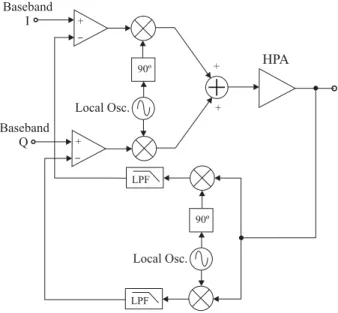
Baseband I Baseband Q + + + + -HPA 90º 90º LPF LPF -Local Osc.Figure 1.1:Basic scheme for Cartesian Loop Feedback.
cartesian loop feedback (CLFB) scheme, exemplified in figure 1.1, the signal is separated into in-phase and quadrature components which allow the correction of amplitude gain and phase shift simultaneously. The HPA output is sampled and then the low pass feed-back components perform an additive pre-distortion of the I-Q components at each input adder, subtracting from the original input the orthogonal error signals introduced by the nonlinearity. A remarkable advantage of this kind of linearizer is that both the signal modulation and amplification processes are jointly considered in the linearization procedure. This means that non-linear distortions originating in sources external to the HPA (at the mixers, for instance) are also compensated.
Along with the well known conditional stability that in general characterize the closed loop feedback control, the most remarkable limitation of FB linearizers is their inability to handle wideband signals. The difficulty in making a feedback network respond uniformly to large changes in the frequency of input envelope, is due to the time delays associated to the amplifier and other components. Since these time delays are frequency-dependent, the difference between the values associated to different sub-carriers within a wide bandwidth becomes significant at frequencies of several MHz or higher.
1.1.2
Feedforward (FF).
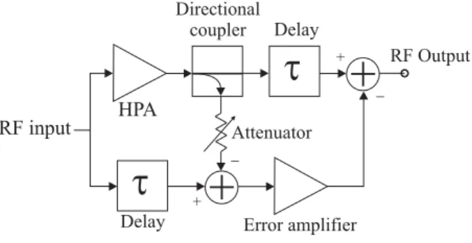
Typical FF schemes employ two closed loops for nonlinear distortion cancellation as shown in the simplified system in figure 1.2. An error signal is generated in the first loop by sub-tracting the original signal at the HPA input from an attenuated version of the HPA output. Then, in the second loop, the error signal so obtained is then amplified and sub-tracted from the aligned RF signal at the output, thus resulting in a distortion-free signal
t
t
Delay
Delay Error amplifier Attenuator Directional coupler
+
+
RF Output + + -HPA RF inputFigure 1.2:Feedforward linearizer.
for transmission. Major disadvantages on the exemplified FF technique include power efficiency loss associated to the need of high gain amplification of the error signal, dissi-pation loss at the final power coupler, complexity of time aligning adjustments and other minor path attenuations. Furthermore, to achieve good linearization, the auxiliary error amplifier must be well designed and set to operate quite linearly in order to keep the compensation signal free from its own distortion [16]. In general, FF can be considered rather complex to implement and hard to incorporate into an existing amplifier structure. Nevertheless, it is easy to find a variety of fixed and adaptive structures [17] based on this principle, starting from the first registered works [18][19] to patented applications for modern single and multicarrier systems [20][21]. In practice, FF has been more ex-tensively implemented for SSPA linearization, given that this type of amplifier presents a low AM/PM distortion level in contrast to TWTs. The less AM/PM distortion the HPA presents, the less critical the time alignment accuracy will be.
1.1.3
Envelope Elimination and Restoration
Modulator Local.Osc. DC supply HPA Limiter Envelope detector X tin( ) X tsc( ) A( )t Mixer
Figure 1.3:Block diagram for Envelope Elimination and Restoration method (EE&R).
The simplified block diagram in figure 1.3 shows the working principle of this method. The input signal Xin(t) corresponds to a intermediate frequency (IF) modulated sub-carrier that conveys the base-band information which is separated into two components: envelope and IF sub-carrier. The latter is obtained by applying a clipping and filtering
stage (limiter) thus providing Xsc(t), which is a constant amplitude signal at IF that preserves the phase information. This constant envelope signal is up-converted to RF and then fed to the HPA which is set to operate with high efficiency, forcing the output to reach saturation. Thus, the stable dynamics of the signal driving the HPA keep the phase information free of non linear distortion. In turn, A(t), the detected IF envelope with the base-band amplitude information, is restored to the HPA output by modulating the DC supply voltage. It is important to note that an external control of DC biasing in amplifiers imply (ideally proportional) changes in the voltage and current supply which allow a linear control of the amplifier’s gain only within a limited range. Therefore, this technique results more appropriate for signals that feature a low envelope variability which is clearly not the case of most multicarrier modulations like OFDM. Practical limitations are related to the non-ideal behaviour of devices like diodes and capacitors used for the implementation of the envelope detector at RF frequencies. For more details, a good implementation reference of this technique is found in [22].
1.1.4
LINC and CALLUM.
Signal component separator DSP + D/A L.Osc.
+
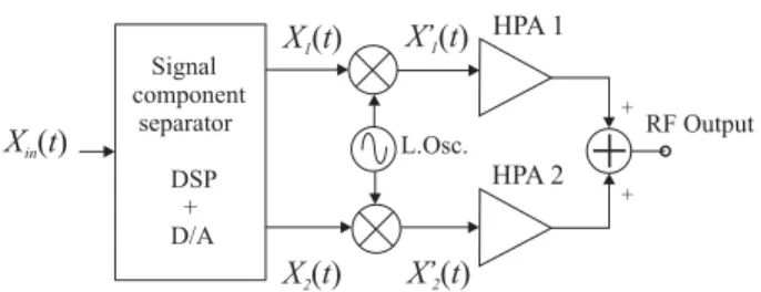
RF Output + + HPA 1 HPA 2 X tin( ) X t1( ) X t2( ) X’ t1( ) X’ t2( )Figure 1.4:Basic block diagram for linearization based on LINC.
The acronym LINC stands for Linear amplification with Nonlinear Components, it was introduced by Cox in the 70’s [23]. This technique is similar to EE&R in the sense of circumventing the nonlinear behaviour of an HPA by driving its input with a constant envelope signal. The principles of this technique can be explained from figure 1.4, and considering a base-band input signal in the form,
Xin(t) =A(t)ejθ(t).
This input signal can be split by means of a DSP into two equivalent amplitude phasors X1(t) = Am
2 ej(θ(t)+ψ(t)) and X2(t) = A2mej(θ(t)−ψ(t)) which are then up-converted obtaining
two constant amplitude passband components given by, X1(t) = Am
2 cos[ωt+θ(t) +ψ(t)] X2(t) = Am
whereψ(t) =cos−1(AA(t)
m), so that,Xin(t) =X1+X2 . Thus, the input modulus variations
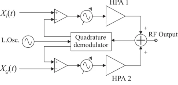
fromA(t) are transferred to identical but opposite sign phase modulations assigned to the constant amplitude phasorsX1(t) and X2(t). These passband signals are then separately fed to nonlinear amplifiers that have been set to operate at maximum power efficiency. Fi-nally, the resulting signals are recombined obtaining the linear amplification of the input signal in pass-band version. Earlier LINC schemes were based on the analog generation of the constant amplitude signals which supposed an added complexity as the signal sepa-rator operated in passband or intermediate frequency. However, later works implemented the signal separator using DSP technology, generating the discrete components X1 and X2 from base-band information. Clearly, one of the the main weakness of this LINC struc-ture is that it is incapable of solving the imbalances between the two signal paths and, particularly, compensating the differences between both nonlinear amplifiers [24]. Some methods based on ACI monitoring at LINC transmitter output have been proposed to overcome the effect of a mismatched HPA pair. In addition, a more complex extension of the LINC method is known as the Combined Analogue Locked Loop Universal Mod-ulator (CALLUM). This structure, shown in the figure 1.5, defines two feedback loops where the outputs of separated VCOs drive the respective HPA inputs. The output signal base-band components are split and fed back using a quadrature demodulator. Then the comparators generate error signals with respect to their corresponding input making the system capable of following and correcting the negative effects of imbalances between the HPAs. Quadrature demodulator L.Osc.
+
RF Output + + HPA 1 HPA 2 X tI( ) X tQ( ) -+ -+Figure 1.5:Block diagram for CALLUM linearizer.
A common disadvantage in both methods (LINC and CALLUM) is the need of high power combining circuitry and the use of two HPAs. Power combiners demand a careful impedance adjustment and require the input signals to be identical and accurately time aligned in order to minimize power losses.
1.1.5
Pre-Distortion.
As previously claimed, along with the feedback and feedforward, pre-distortion is so far one of the most extended linearization techniques. Pre-distortion (PD) can be seen as similar to feedback in that the nonlinear compensation is applied before the signal is presented to the nonlinear HPA input. However, most limitations of FB structures do
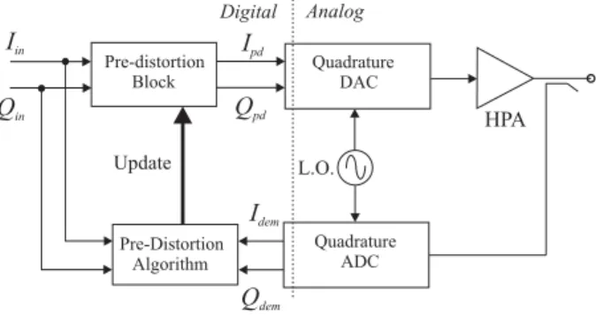
Update L.O. HPA Iin Ipd Idem Qpd Qin Qdem Pre-distortion Block Quadrature ADC Pre-Distortion Algorithm Analog Digital Quadrature DAC
Figure 1.6: Block diagram for adaptive digital pre-distortion.
not affect PD which is similar to FF in terms of stability and bandwidth capacities. From a functional point of view, PD is probably the most intuitive linearization strategy. If a HPA characteristic is seen as a memoryless input-to-output transfer function, then PD can be defined as its exact inverse transfer function. In this case, when the PD output is specified as the new input to the HPA nonlinear function, a one-to-one linear mapping between the input and output of the PD+HPA combination is produced.
Let us recall that the most credited alternatives previously mentioned suffer several drawbacks: FB features conditional stability and is narrow-band/single carrier oriented, while FF is rather expensive and difficult to add to an existing HPA structure, since the error signal has to be highly (and linearly!) amplified and RF-coupled at the output of the HPA, subsequently losing power efficiency. Digital Pre-Distortion (PD) has in turn proved to be the most suitable solution for adaptive linearization in wideband communications because of its relative implementation simplicity and its integrability as a low power consumption stand-alone unit in existing non-linear transmitters [25].
Rough approximations to the ideal PD characteristic for a given HPA can be obtained using nonlinear devices, such as diodes or transistors in their nonlinear zone, to construct analog pre-distorters. Many proposals and implementations based on analog circuitry are open loop second or third-order pre-distorters intended to work either at IF or even higher (near microwave) carrier frequencies [26] [27]. Nevertheless, these applications are appropriate for moderated linearity requirements or when the HPA presents a relatively low nonlinearity level. More advanced studies on analog pre-distortion, such as [28], include higher order polynomial based analysis and out-of-band power monitoring for the pre-distortion adaptation. Although analog techniques have reported promising results offering low cost and complexity, more general schemes have been required to linearize more nonlinear amplifiers as new modulation formats have increased linearization demands. Thus, DSP techniques and hardware capabilities improvement have converted adaptive digital pre-distortion into a research area in constant evolution with a variety of approaches.
It is possible to find many different configurations for digital PD processing systems. However, all configurations have the same basic principle shown in figure 1.6. In the general block scheme, the transmitted RF signal from the output of the HPA is downconverted and split into discrete quadrature components. The base-band samples are then given to an adaptation algorithm which basically compares them with the corresponding samples of the reference input signal, providing information periodically to the adaptation algorithm. The setting parameters of the PD process, which is completely performed in the discrete domain, are updated by searching for the minimum I/O error or another suitable cost criterion, in such a way that after a short convergence time the PD block could operate as the exact inverse to the base-band equivalent HPA transfer characteristic.
The first suggested and still widely employed digital PD type is the mapping PD. This mapping is based on the use of a look-up table and additional DSP techniques for fitting and estimation. By using 2D LUT the complex input signals composed of the I-Q components can be mapped to a new constellation of cartesian components. Usually, RAM space is used to store the additive PD values for the I-Q components. Disadvantages are the large size of LUTs needed to reach high accuracy (2 Mword for 10 bit representation of the input signal) and the dependence of the operative bandwidth of the pre-distorter on the sampling rate of the system. Dependence on system sampling rate is, however, a general limitation for all digital PD schemes. More memory efficient applications have been developed using Polar PD instead of cartesian mapping. Such systems allow a considerable reduction in the table size (reducing up to four orders of magnitude with respect to the PD LUT mapping) and consequently, adaptation times can be minimized using interpolation to accelerate the LUT filling. The polar PD takes advantage of the fact that the amplifier characteristic is a function that only depends on the input modulus. Unlike the mapping PD, which is an adding correction, the polar PD uses the input amplitude determined by the cartesian input components to address the LUT containing the amplitude gain factors. The amplitude resulting from the multiplication with this addressed gain table is used to address a second table containing phase rotation data applicable through a simple matrix operation. The memory efficiency achieved with the one dimensional addressing of polar PD is in opposition to the increased computational load introduced by the rectangular to polar conversions involved in this technique. In addition, another weak point of polar PD is that its performance has been shown to depend critically on the perfect adjustment of quadrature modulators and demodulators [29] while such dependence has been reported not so severe for mapping and complex gain PD [30].
The PD approaches more closely related to the final linearization schemes included in this work are those using Complex Gain PD. Such systems are known to need dramatically fewer operations than mapping and polar PD [31]. Complex valued gain factors are stored in cartesian form so that the input signal is pre-distorted by a single step complex multiplication. Results on this kind of schemes, such as [32], reveal that a significant reduction of ACI (> 20 dB) due to nonlinear distortion can be obtained operating the HPA with good power efficiency. The flat out-of-band spectral floor (-50 dB with respect to the in-band spectrum level) and the accuracy of the complex gain
PD therein exhibited, were reported to be highly affected by the imperfections of the RF quadrature modulators and demodulators. Nevertheless, these imperfections can be diminished by generating an IF interface through discrete means.
Other discrete PD approaches avoid the use of any kind of LUTs. This is the case of polynomial PD where the coefficients of higher order polynomial series are adjusted adaptively by means of an optimization algorithm. Previous work on polynomial approaches, though interesting from the mathematical point of view, still require a thorough evaluation of the trade-offs between linearization performance and computa-tional complexity to justify its application in a real scheme [33] [34] [35]. Furthermore, another proposed way to implement PD is based on the characterization of either the PD transfer function or the PD complex gain through the adaptive estimation of few PD coefficients. The PD coefficients set, associated to membership functions, can span the input dynamic range allowing us to perform base-band PD over the input data via interpolation [36]. Additionally, the analysis of the alterations introduced by a nonlinear distortion on the input data statistics (PDF) has revealed an interesting potential for the application of the Order Statistics of the distorted signal in the estimation of PD [37]. Prior explorations of these techniques are referred and detailed in this work and constitute the basis and motivation for the PD schemes herein presented.
Let us enumerate some necessary observations and criteria regarding a final imple-mentation of digital PD :
1. A pre-distorter generates some spectral regrowth (SR) since it is itself a nonlinearity. This means that the intermediate stages must be able to handle a wider useful bandwidth without introducing additional linear distortions.
2. PD is said to be insensitive to loop delay since feedback is used only for adaptation of the PD coefficients rather than for simultaneous corrections. Nevertheless, most digital adaptation algorithms assume that the sampled output and reference signal information are well aligned sample streams. Therefore, the time delays typically in-troduced by analog chains must be compensated before estimation of pre-distortion coefficients. Some previously published work on time alignment for PD schemes [38][39] is appended to show the importance of this impairment over the presented techniques and to suggest possible solutions.
3. It is desirable that the PD configuration be able to match the inverse HPA regardless of the order of its nonlinear characteristics. This means that no prior knowledge is to be assumed about the smoothness or monotony of the transfer curves. Besides, the PD linearization performance is expected to be minimally restricted to modulation format.
4. The implementation feasibility of any digital linearization process will rely on the power and computational load associated to the DSP algorithm design. In addition, since the OFDM signal already defined in the standards considers a framing format
with pilot signals and training sequences, linearization systems are expected to be non-intrusive so as not to affect the signal continuity nor require special training sequences.
Finally, although a review of the state of the art in linearization techniques would deserve annual updates, it is not the objective of this work to provide a complete peer insight of all the new proposals and specific advances. Thence, for further technical details we refer the readers to [40],[25] and [41] where well documented and more exhaustive historical revisions of this field are provided.