Technical Report Documentation Page
1. Report No.
FHWA/TX-11/0-6658-P3
2. Government Accession No. 3. Recipient's Catalog No. 4. Title and Subtitle
TEXAS FLEXIBLE PAVEMENTS AND OVERLAYS: DATA ANALYSIS PLANS AND REPORTING FORMAT
5. Report Date September 2011
Published: January 2012 6. Performing Organization Code 7. Author(s)
Lubinda F. Walubita, Gautam Das, Elida Espinoza, Jeongho Oh, Tom Scullion, Soheil Nazarian, Imad Abdallah, and Jose L. Garibay
8. Performing Organization Report No. Report 0-6658-P3
9. Performing Organization Name and Address
Texas Transportation Institute, The Texas A&M University System College Station, Texas 77843-3135
Center for Transportation Infrastructure Systems
The University of Texas at El Paso, El Paso, Texas 79968-0582
10. Work Unit No. (TRAIS) 11. Contract or Grant No. Project 0-6658
12. Sponsoring Agency Name and Address Texas Department of Transportation
Research and Technology Implementation Office P. O. Box 5080
Austin, Texas 78763-5080
13. Type of Report and Period Covered Technical Report:
November 2010–September 2011 14. Sponsoring Agency Code
15. Supplementary Notes
Project performed in cooperation with the Texas Department of Transportation and the Federal Highway Administration.
Project Title: Collection of Materials and Performance Data for Texas Flexible Pavements and Overlays URL: http://tti.tamu.edu/documents/0-6658-P3.pdf
16. Abstract
This five-year project was initiated to collect materials and pavement performance data on a minimum of 100 highway test sections around the State of Texas, incorporating flexible pavements and overlays. Besides being used to calibrate and validate mechanistic-empirical (M-E) design models, the data collected will also serve as an ongoing reference data source and/or diagnostic tool for TxDOT engineers and other transportation professionals. Towards this goal, this interim report provides a documentation of the comprehensive data analysis plans that were developed to analyze the collected data. The data collection plans are documented elsewhere as Report 0-6658-P1.
As documented here, the data analysis plans were designed to cover various key aspects, including the following: (1) the tools and test methods used to measure/collect the data, (2) the type and format of the data measured/collected, (3) the raw data reduction processes for each data type, (4) the software used to process and analyze the measured/collected data, (5) the analytical methods and models used to analyze the measured/collected data, (6) the dimensional and/or quantitative units of the measured/computed parameters, and (7) the data reporting format including how the data will be accessed and displayed from the MS Access Data Storage System (i.e., tables, graphs, bar charts, etc.). Specifically, the data to be analyzed included the following: (1) laboratory and field test data including asphalt-binders, hot-mix asphalt (HMA) mixes, base, and subgrade soil materials; (2) traffic data; and (3) environmental and climatic data.
17. Key Words
HMA, Flexible Pavement, Overlay, /Databases, Perpetual Pavement, PP, LTPP, TSFP, M-E Models
18. Distribution Statement
No restrictions. This document is available to the public through NTIS:
National Technical Information Service Alexandria, Virginia 22312
http://www.ntis.gov
19. Security Classif. (of this report) Unclassified
20. Security Classif. (of this page) Unclassified
21. No. of Pages
136 22. Price
TEXAS FLEXIBLE PAVEMENTS AND OVERLAYS:
DATA ANALYSIS PLANS AND REPORTNG FORMAT
by Lubinda F. Walubita
Associate Transportation Researcher Texas Transportation Institute
Gautam Das
Assistant Transportation Researcher Texas Transportation Institute
Elida Espinoza Student Worker II Texas Transportation Institute
Jeongho Oh
Assistant Research Engineer Texas Transportation Institute
Tom Scullion Senior Research Engineer Texas Transportation Institute
Soheil Nazarian, Ph.D., P.E. Center Director
Center for Transportation Infrastructure Systems Imad Abdallah, E.I.T.
Associate Director
Center for Transportation Infrastructure Systems Jose L. Garibay
Researcher
Center for Transportation Infrastructure Systems
Report 0-6658-P3 Project 0-6658
Project Title: Collection of Materials and Performance Data for Texas Flexible Pavements and Overlays
Performed in cooperation with the Texas Department of Transportation
and the
Federal Highway Administration September 2011
Published: January 2012
TEXAS TRANSPORTATION INSTITUTE CENTER FOR TRANSPORTATION
The Texas A&M University System INFRASTRUCTURE SYSTEMS
College Station, Texas 77843-3135 University of Texas at El Paso
v
DISCLAIMER
The contents of this report reflect the views of the authors, who are responsible for the facts and the accuracy of the data presented herein. The contents do not necessarily reflect the official view or policies of the Federal Highway Administration (FHWA) or the Texas
Department of Transportation (TxDOT). This report does not constitute a standard,
specification, or regulation, nor is it intended for construction, bidding, or permit purposes. The United States Government and the State of Texas do not endorse products or
manufacturers. Trade or manufacturers’ names appear herein solely because they are considered essential to the object of this report. The researcher in charge was Lubinda F. Walubita.
vi
ACKNOWLEDGMENTS
This project was conducted for TxDOT, and the authors thank TxDOT and FHWA for their support in funding this research project. In particular, the guidance and technical assistance provided by the project director (PD) Brett Haggerty, of TxDOT, proved invaluable. The
following project advisors also provided valuable input throughout the course of the project and their guidance is duly acknowledged: David Debo, Todd Copenhaver, Jaime Gandara,
Stephen Guerra, Joe Leidy, Mark McDaniel, Jerry Peterson, and Billy Pigg.
Special thanks are also extended to the following people for their assistance with this study: Jason Huddleston (TTI), Hossain A. Tanvir (TTI), Jun Zhang (TTI), Rubayyat Hashmi (TTI), Sheng Hu (TTI), Abu M. Faruk (TTI), Lee Gustavus (TTI), Tony Barbosa (TTI), Fujie Zhou (TTI), and Manuel Celaya (UTEP).
vii
TABLE OF CONTENTS
LIST OF FIGURES ... ix LIST OF TABLES ... x LIST OF NOTATIONS AND SYMBOLS ... xi CHAPTER 1: INTRODUCTION ... 1-1
OBJECTIVES AND SCOPE OF WORK ... 1-1
SUMMARY ... 1-2 CHAPTER 2: LAB TEST DATA ANALYSIS PART I ... 2-1
MATERIAL SAMPLING AND QUANTITIES ... 2-1
TEST SPECIFICATIONS AND DATA ANALYSIS METHODS ... 2-2
DATA REPORTING FORMAT AND ACCESS ... 2-4
SUMMARY ... 2-7 CHAPTER 3: LAB TEST DATA ANALYSIS: PART II ... 3-1
MATERIAL SAMPLING AND QUANTITIES ... 3-1
TEST SPECIFICATIONS AND DATA ANALYSIS METHODS ... 3-2
DATA REPORTING FORMAT AND ACCESS ... 3-11
SUMMARY ... 3-13 CHAPTER 4: LAB TEST DATA ANALYSIS: PART III ... 4-1
MATERIAL SAMPLING AND QUANTITIES ... 4-1
TEST SPECIFICATIONS AND DATA ANALYSIS METHODS ... 4-1
SUMMARY ... 4-12 CHAPTER 5: FIELD TEST DATA ANALYSIS: PART I ... 5-1
TEST SECTION CHARACTERISTICS ... 5-1
CRACKING ... 5-5
SURFACE RUTTING ... 5-6
SURFACE PROFILES ... 5-8
TEXTURE AND SKID NUMBER ... 5-10
SUMMARY ... 5-10 CHAPTER 6: FIELD TEST DATA ANALYSIS: PART II ... 6-1
PORTABLE SEISMIC PAVEMENT ANALYZER TESTS ... 6-1
DYNAMIC CONE PENETROMETER (DCP) TEST ... 6-3
FALLING WEIGHT DEFLECTOMETER (FWD) TEST ... 6-6
SUMMARY ... 6-9 CHAPTER 7: FIELD TEST DATA ANALYSIS: PART III ... 7-1
GROUND PENETRATING RADAR (GPR) ... 7-1
CORING ... 7-3
SUMMARY ... 7-5 CHAPTER 8: TRAFFIC DATA ANALYSIS ... 8-1
RAW DATA FORMAT ... 8-1
viii
SUMMARY ... 8-4 CHAPTER 9: ENVIRONMENTAL AND CLIMATIC DATA ANALYSIS ... 9-1
CLIMATIC DATA GENERATION ... 9-1
GROUNDWATER TABLE DATA ... 9-4
SUMMARY ... 9-5 CHAPTER 10: SUMMARY AND RECOMMENDATIONS ... 10-1 REFERENCES ... R-1 APPENDIX A: LAB TEST DATA ANALYSIS (ASPHALT-BINDERS) ... A-1 APPENDIX B: LAB TEST DATA ANALYSIS (HMA MIXES) ... B-1 APPENDIX C: BASE AND SUBGRADE SOIL TESTS ... C-1 APPENDIX D: FIELD TEST DATA ANALYSIS ... D-1
ix
LIST OF FIGURES
Figure 2-1. Plant-Mix Sampling from the Construction Site. ... 2-2
Figure 2-2. Specific Gravity Data for PG 64-22 (US 59, Atlanta District, TX). ... 2-5
Figure 2-3. DSR Data for PG 64-22 (US 59, Atlanta District, TX). ... 2-5
Figure 2-4. MSCR Test Data for PG 64-22 (US 59, Atlanta District, TX). ... 2-5
Figure 2-5. BBR-Flexural Stiffness Bar Chart for PG 64-22 (US 59, Atlanta District, TX). ... 2-6
Figure 2-6. DSR Bar Chart for PG 64-22 (US 59, Atlanta District, TX). ... 2-6
Figure 3-1. |E*| Master-Curve for Type D Plant-Mix (US 59, Atlanta District). ... 3-7
Figure 3-2. Hamburg Test Data for US 59 Plant Mix (Atlanta District). ... 3-12
Figure 3-3. Overlay Test Data for US 59 Plant Mix (Atlanta District). ... 3-12
Figure 3-4. Plot of Rut Depth vs. Load Passes Obtained from US59 Hamburg Data. ... 3-12
Figure 3-5. OT Results from US 59 (Atlanta District). ... 3-13
Figure 4-1a. Typical Average Gradation Curve from an El Paso Base. ... 4-2
Figure 4-1b. Typical Average Gradation Curves for Raw Subgrade Soil (Loop 480, Laredo). .. 4-3
Figure 4-1c. Hydrometer Test Results for Raw Subgrade Soil (Loop 480, Laredo). ... 4-3
Figure 4-2. Example of MD for Raw Subgrade Soil (Loop 480, Laredo). ... 4-6
Figure 4-3. Typical Resilient Modulus Test Results. ... 4-10
Figure 5-1. Steps for Selecting Field Test Sections. ... 5-2
Figure 5-2. Road Signs for the Test Sections. ... 5-4
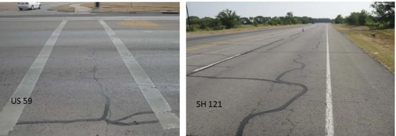
Figure 5-3. Cracking on US 59 (Atlanta District) and SH 121 (Paris District) Prior to Overlay Placement in Spring 2011. ... 5-6
Figure 5-4. Example of Crack Survey Map for US 59, Atlanta District (Spring 2011). ... 5-6
Figure 5-5. Surface Rut Measurements on SH 114 (Fort Worth, Summer 2011). ... 5-7
Figure 5-6. Graphical Plot of Rut Measurements on SH 114—Superpave (Fort Worth). ... 5-8
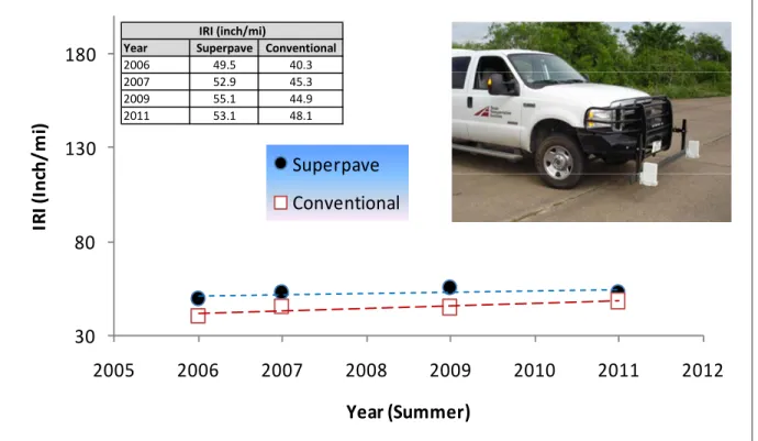
Figure 5-7. Example of IRI Data for SH 114 (Fort Worth) as a Function of Time. ... 5-9
Figure 6-1. The PSPA Device. ... 6-2
Figure 6-2. PSPA Data from Untreated and Treated Base and Subgrade. ... 6-2
Figure 6-3. Illustration of DCP Testing. ... 6-3
Figure 6-4. Example of DCP Data Collected from US 59, Atlanta District. ... 6-5
Figure 6-5. Example FWD Testing on SH 114 (Fort Worth, Summer 2011). ... 6-6
Figure 6-6. FWD W1 Deflection on SH 114 Superpave (Fort Worth). ... 6-8
Figure 6-7. FWD W7 Deflection on SH 114 Superpave (Fort Worth). ... 6-8
Figure 7-1. Processed GPR Data for SH 114 Conventional (SH 114, Fort Worth). ... 7-2
Figure 7-2. Defective Cores from US 59 (Atlanta District) Prior to Overlay. ... 7-3
Figure 7-3. Intact Cores from SH 114 Conventional (Fort Worth). ... 7-4
Figure 7-4. Cores from SH 121 (Paris District) Prior to Overlay. ... 7-4
Figure 7-5. Cores from US 271 (Paris District) Prior to Overlay. ... 7-4
Figure 8-1. An Example of Raw Traffic Data Collected on US 59 (Atlanta District). ... 8-2
Figure 8-2. FHWA Vehicle Classifications. ... 8-3
Figure 8-3. Vehicle Class Distribution of US 59 (Atlanta District). ... 8-4
Figure 9-1. M-E PDG Climatic Data Generation Screen ... 9-2
Figure 9-2. Air Temperature Monthly Variation Using M-E PDG Weather Station Data. ... 9-3
Figure 9-3. Precipitation Monthly Variation Using M-E PDG Weather Station Data. ... 9-3
Figure 9-4. Comparison of Monthly Air Temperature Variation between M-E PDG and
x
LIST OF TABLES
Table 2-1. Test Specification and Data Analysis Methods for Asphalt-Binders
(Extracted). ... 2-3
Table 2-2. DSR (T 315) Test Results: Extracted PG 64-22, US 59 (Atlanta District, TX). ... 2-4
Table 3-1. Test Specification and Data Analysis Procedures for HMA Mixes. ... 3-2
Table 3-2. Asphalt-Binder Extractions and Gradations for Type D Plant-Mix from US 59
(Atlanta District, TX). ... 3-3
Table 3-3. Hamburg Test Results for Type D Plant-Mix from US 59 (Atlanta District,
TX). ... 3-4
Table 3-4. Overlay Test Results for Type D Plant-Mix from US 59 (Atlanta District, TX). ... 3-4
Table 3-5. OT Fracture Properties Results for Type D Plant-Mix from US 59 (Atlanta
District, TX). ... 3-6
Table 3-6. |E*| Results for Type D Plant-Mix from US 59 (Atlanta District, TX) ... 3-7
Table 3-7. RLPD Results for Type D Plant-Mix from US 59 (Atlanta District, TX). ... 3-9
Table 3-8. IDT Results for Type D Plant-Mix from US 59 (Atlanta District, TX). ... 3-9
Table 3-9. TTI HMA Thermal Coefficient Results for Type D US 59 (Atlanta District,
TX). ... 3-11
Table 4-1a. Typical Index Test Results from an El Paso Base. ... 4-4
Table 4-1b. Typical Index Test Results for Raw Subgrade Soil (Loop 480, Laredo). ... 4-4
Table 4-2. Typical Results for Soil Classification of an El Paso Base. ... 4-5
Table 4-3. Typical Moisture Density Test Results from an El Paso Base. ... 4-5
Table 4-4. Typical Results from Strength Tests on an El Paso Base. ... 4-7
Table 4-5. Typical Results for Resilient Modulus Parameters on El Paso Base. ... 4-8
Table 4-6. Typical Permanent Deformation Parameters for El Paso Base Material. ... 4-9
Table 4-7. Specific Gravity Results for Raw Subgrade Soil (Loop 480, Laredo). ... 4-12
Table 5-1. Variables to Consider when Selecting Test Sections. ... 5-2
Table 5-2. Field Test Procedures and Data Characteristics—Part I. ... 5-4
Table 5-3. Tabulation of Rut Measurements for SH 114—Superpave (Fort Worth). ... 5-7
Table 6-1. Field Test Procedures and Data Characteristics—Part II. ... 6-1
Table 6-2. Example of DCP Processed Data (US 59, Atlanta District). ... 6-5
Table 6-3. FWD Moduli Results from US 59, Atlanta District (Spring 2011). ... 6-7
Table 7-1. Field Test Procedures and Data Characteristics—Part III. ... 7-1
Table 8-1. Summary of Traffic Data Analysis for US 59 (Atlanta) ... 8-4
Table 9-1. Groundwater Table Depth Data. ... 9-5
xi
LIST OF NOTATIONS AND SYMBOLS
AASHTO American Association of State Highway and Transportation Officials
AC Asphalt-binder content
AV Air voids
Avg Average
CV Coefficient of variation
CTB Cement-treated base
CTIS Center for Transportation Infrastructure Systems
DCP Dynamic cone penetrometer
EB Eastbound direction
FHWA Federal Highway Administration
FWD Falling weight deflectometer
IRI International roughness index
GIS Geographical Information System
GPS Geographical positioning system
FWD Falling weight deflectometer
HMA Hot-mix asphalt
LTB Lime-treated base
LTPP Long-Term Pavement Performance
M-E Mechanistic Empirical
MEPDG Mechanistic Empirical Pavement Design Guide
MS Microsoft©
MR Resilient modulus
NB Northbound direction
PD Permanent deformation
PMIS Pavement Management Information System
PP Perpetual Pavement
PSI Pavement serviceability index
PSPA Portable seismic property analyzer
PVMNT Pavement
xii
QC Quality control
SB Southbound direction
SPS Specific pavement studies
TFPDB Texas Flexible Pavement Database
TSFP Texas Successful Flexible Pavement
TTI Texas Transportation Institute
TxDOT Texas Department of Transportation
UT University of Texas at Austin
UTEP University of Texas at El Paso
WB Westbound direction
1-1
CHAPTER 1: INTRODUCTION
Proper calibration of pavement design and rehabilitation performance models to conditions in Texas is essential for cost-effective flexible pavement designs. The degree of excellence with which TxDOT’s pavement design models is calibrated will determine how optimally literally billions of dollars of future roadway investment capital will be spent. The magnitude of benefits and consequences involved makes this research project one of the more important research efforts that the department has undertaken in recent memory.
Collection of quality and reliable pavement performance data on a sustained basis will thus be the main goal of this project. Inevitably, this presents a perfect opportunity to calibrate and validate the currently design methods and models for both flexible pavements and overlays. The calibration of these models to Texas local conditions will result in pavement designs that are more economical, with superior performance expectation, in the long term.
OBJECTIVES AND SCOPE OF WORK
The primary goal of this five-year project is to collect materials and pavement
performance data on a minimum of 100 highway test sections around the State of Texas. The data collected is being used to calibrate and validate the mechanistic-empirical (M-E) design models. It will also serve as an ongoing reference source and/or diagnostic tools for TxDOT engineers and other transportation professionals.
Towards this goal and as documented here, the specific objective of this task was to develop sound data analysis plans and, among others, to address the following key aspects of the data collection process:
• The tools and test methods used to collect the data.
• The type and format of the data that is being measured and collected.
• The raw data reduction process for each data type.
• The software being used to process and analyze the measured/collected data.
• The analytical methods, techniques, and models being used to analyze the
measured/collected data.
1-2
• The data reporting format including how the data will be accessed and displayed from the
MS Access Data Storage System (i.e., tables, graphs, bar charts, etc.).
Having sound data analysis plans is a very critical aspect and an integral part of the data collection plan to ensure quality data. It is meaningless to have robust data collection plans without sound data analysis plans or appropriate data analysis models. Data collection plans are
documented elsewhere as Report 0-6658-P1 (Walubita et al. 2011).
This report, denoted here as Product 0-6658-P3, documents the data analysis plans that were formulated in the early stages of this project to process and analyze the laboratory, field, traffic, environmental, and climatic data. The scope and contents of the report covers the following items:
• Chapter 2: Lab test data analysis: part I (asphalt-binders). • Chapter 3: Lab test data analysis: part II (HMA mixes).
• Chapter 4: Lab test data analysis: part III (base and subgrade soil materials). • Chapter 5: Field test data analysis: part I (cracking, rutting, profiles, skid, etc.). • Chapter 6: Field test data analysis: part II (PSPA, DCP, and FWD).
• Chapter 7: Field test data analysis: part III (forensics—GPR and coring). • Chapter 8: Traffic data analysis.
• Chapter 9: Environmental and climatic data analysis. • Chapter 10: Summary and recommendations.
Some appendices of important data are included at the end of the report, along with a CD of some models, analysis demonstrations, and example results.
SUMMARY
This introductory chapter discusses the background and research objectives along with the scope and content of the report. Specifically, this report, denoted here as Product 0-6658-P3, documents the data analysis plans that were formulated to process and analyze the laboratory, field, traffic, environmental, and climatic data that is being collected.
2-1
CHAPTER 2: LAB TEST DATA ANALYSIS PART I
The data analysis plans discussed in this chapter and denoted as Part I pertain to the asphalt-binder tests that were recommended to generate the required rheological and engineering properties as well as PG grading of the extracted binders, These tests include the following:
• The specific gravity (SG).
• The viscosity.
• The dynamic shear rheometer (DSR).
• The bending beam rheometer (BBR).
• The MSCR.
• The elastic recovery (ductility).
• PG grading of the asphalt-binders.
In general, the data analysis plans incorporate the following aspects: the test
specification, the analysis procedure, and the reporting format. The unit of measurement and interpretation of each data type along with typical or threshold values are also indicated. A summary of key points concludes the chapter.
MATERIAL SAMPLING AND QUANTITIES
As documented in the data collection plans (Report 0-6658-P1), all the above tests are based on binder extractions (Tex-210-F) from the plant-mix hauled from: a) the production plant, b) directly from the site, or c) from cores; all sources that represent in-situ field conditions. If hauled from the site, which is preferred, the plant-mix should be sampled from a minimum of three different trucks but not more than five, precisely at the location of the test section (see Figure 2-1). In a nutshell, the plant-mix or field cores should be sampled/cored from a minimum of three locations within the test section. The Texas method Tex-210-F will be used for
2-2
Figure 2-1. Plant-Mix Sampling from the Construction Site.
The approximate material (plant-mix/cores) requirement to conduct all these
asphalt binder tests per mix type or HMA layer is 100 lb. Thus, about 34 lb of material or cores should be sampled per sampling location. TxDOT recommended that the number of replicate samples for most of these tests be reduced from three to one, due to repeatable results when dealing with homogeneous asphalt-binder materials and the need to optimize resources.
TEST SPECIFICATIONS AND DATA ANALYSIS METHODS
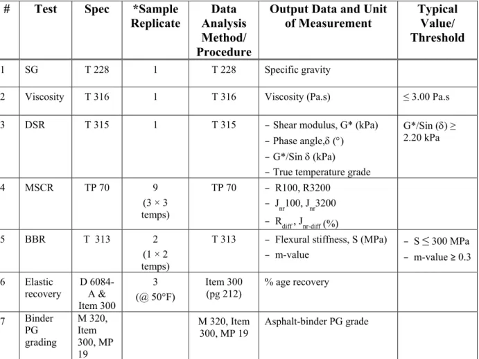
Table 2-1 lists the test specifications, analysis methods, and the output data along with the expected typical values or thresholds. In general, all the analysis procedures and methods are based on pre-existing standard specifications for asphalt-binders, incorporating Texas and US national standards. Test plan proposals for the asphalt-binders are included in Appendix A.
2-3
Table 2-1. Test Specification and Data Analysis Methods for Asphalt-Binders (Extracted). # Test Spec *Sample
Replicate
Data Analysis Method/ Procedure
Output Data and Unit of Measurement
Typical Value/ Threshold
1 SG T 228 1 T 228 Specific gravity
2 Viscosity T 316 1 T 316 Viscosity (Pa.s) ≤ 3.00 Pa.s 3 DSR T 315 1 T 315 −Shear modulus, G* (kPa)
−Phase angle,δ (°) −G*/Sin δ (kPa)
−True temperature grade
G*/Sin (δ) ≥ 2.20 kPa 4 MSCR TP 70 9 (3 × 3 temps) TP 70 − R100, R3200 − Jnr100, Jnr3200 − Rdiff , Jnr-diff (%) 5 BBR T 313 2 (1 × 2 temps)
T 313 − Flexural stiffness, S (MPa) − m-value − S ≤ 300 MPa − m-value ≥ 0.3 6 Elastic recovery D 6084-A & Item 300 3 (@ 50°F) Item 300 (pg 212) % age recovery 7 Binder PG grading M 320, Item 300, MP 19 M 320, Item 300, MP 19 Asphalt-binder PG grade *Number of replicate samples based on TxDOT recommendations.
Appendix A shows the detailed test specifications and thresholds, specifically the TxDOT specification Item 300 and the AASHTO TP 70. Table 2-2 shows an example of the
2-4
Table 2-2. DSR (T 315) Test Results: Extracted PG 64-22, US 59 (Atlanta District, TX).
Sample T#1 = 58°C T#2 = 64°C T#3 = 70°C True Grade Temp (°C) G* (kPa) δ (°) G*/Sin(δ) (kPa) G* (kPa) δ (°) G*/Sin(δ) (kPa) G* (kPa) δ (°) G*/Sin(δ) (kPa) Sample# 1 7.14 82.90 7.20 3.24 84.90 3.25 1.59 86.40 1.59 67.26 Sample# 2 7.00 82.90 7.06 3.13 85.00 3.14 1.50 86.40 1.51 66.90 Sample# 3 6.03 83.30 6.08 2.67 85.20 2.68 1.25 86.60 1.25 65.55 Avg 6.72 83.03 6.78 3.01 85.03 3.02 1.45 86.47 1.45 66.57 Stdev 0.604 0.230 0.610 0.302 0.153 0.302 0.176 0.116 0.178 0.901 CV 8.99% 0.28% 9.00% 10.03% 0.18% 10.00% 12.18% 0.13% 12.26% 1.35%
Clearly, Table 2-2 shows that the PG 64-22 asphalt-binder meets the T 315 high temperature requirements at 64°C. However, the true temperature grade based on Table 2-2 is actually 66.6°C. The table also shows good repeatability with low variability for this test, hence the TxDOT recommendation to consider only one replicate test sample.
DATA REPORTING FORMAT AND ACCESS
In general, most of the asphalt-binder test data are reported and may be accessed in one or more of the following formats from the MS Access Data Storage System:
• Numerical listing.
• Tabular listing.
• Bar chart.
• Graphical format (i.e., plots, curves, etc.).
Currently, investigations are also under way to facilitate direct data exporting from the MS Access Data Storage System. Figures 2-2 through 2-6 show examples of some of the asphalt-binder data extracted from the MS Access Data Storage System.
2-5
Figure 2-2. Specific Gravity Data for PG 64-22 (US 59, Atlanta District, TX).
Figure 2-3. DSR Data for PG 64-22 (US 59, Atlanta District, TX).
2-6
Avg Sample1
‐18 °C ‐12°C ‐18 °C ‐12°C ‐18 °C ‐12°C ‐18 °C ‐12°C
Sample2 Sample3
Figure 2-5. BBR-Flexural Stiffness Bar Chart for PG 64-22 (US 59, Atlanta District, TX).
Avg Sample1 Sample2 Sample3
58 °C 64°C 70 °C 58 °C 64°C 70 °C 58 °C 64°C 70 °C 58 °C 64°C 70 °C
2-7 SUMMARY
This chapter presented the data analysis plans for the asphalt-binders including the test specifications, analysis procedures, and the data reporting format. Overall, all the data analysis procedures and methods were consistent with Texas and US national standards for testing, analyzing, reporting, and interpretation of the asphalt-binder test data. Demonstration examples of the test results and extracts from the MS Access Data Storage System were also discussed. Test plan proposals for asphalt-binders are included in Appendix A.
3-1
CHAPTER 3: LAB TEST DATA ANALYSIS: PART II
Part II of the laboratory test data analysis plans covers the data collection format, raw data reduction process, and analysis procedure for the following HMA mixes:
• Asphalt-binder extractions and gradations.
• The Hamburg rutting test.
• The Overlay Tester (OT).
• The OT for measuring fracture properties.
• The dynamic modulus (DM).
• The repeated load permanent deformation (RLPD) test.
• The Indirect-tension (IDT) test.
• The HMA thermal coefficient test.
As discussed in the subsequent sections of this chapter, the data analysis plans also includes the analysis models and software used. The unit of measurement and interpretation of each data type along with typical or threshold values are also indicated. A summary of key points concludes the chapter.
MATERIAL SAMPLING AND QUANTITIES
As documented in the data collection plans (Report 0-6658-P1), all the above tests will be based only on plant-mix materials and field cores that represent in-situ field conditions (Walubita et al. 2011). Unless otherwise circumstances do not permit, then raw materials can be considered. The plant-mix material will either be hauled from the production plant or directly from the site. If hauled from the site, which is preferred, the plant-mix should be sampled from a minimum of three but not more than five different trucks, precisely at the location of the test sections (see Figure 2-1). In a nutshell, the plant-mix or field cores should be sampled/cored from a minimum of three locations within the test section. Where extraction tests such as determining the asphalt-binder content and aggregate gradation are required, the Texas method Tex-210-F will be used (TxDOT 2011).
3-2
The approximate material (plant-mix/cores) requirement to conduct all these HMA tests per mix type or HMA layer is 500 lb. Thus, about 167 lb of material or cores should be sampled per sampling location. Except for the Hamburg test, a minimum of three replicate samples will be used per test per material type.
TEST SPECIFICATIONS AND DATA ANALYSIS METHODS
Table 3-1 lists the test specifications and data analysis procedures (based on Texas as well as national standards), and output data for the HMA mixes along with some typical thresholds. Test plan proposals for the HMA mixes are included in Appendix B.
Table 3-1. Test Specification and Data Analysis Procedures for HMA Mixes. # Test Spec *Sample
Replicate
Data Analysis Method/ Procedure
Output Data and Unit of Measurement Typical Value/ Threshold 1 AC extractions & gradations
Tex-210-F 3 Tex-210-F - Asphalt content (%) - Gradation & particle size distribution
−
2 Hamburg Tex-242-F 1 (1 set of 2) Tex-242-F Rut depth (mm) < 12.5 mm 3 Overlay Test
(OT) Tex-248-F @ 77°F 5 Tex-248-F - Maximum load (lbf) No. of cycles to failure ≥ 300 (typical mixes) ≥ 750(CAM) 4 OT fracture properties Report 0-5798-2, PP 97 5 Report 0-5798-2, PP 97 Fracture parameters, A & n − 5 Dynamic modulus (DM) AASHTO TP 62-03 3 AASHTO TP 62-03
Dynamic modulus ,|E*|
(ksi) − 6 Repeated Load Permanent Deformation test (RLPD) Report 0-5798-2 a) 104°F @ 20 psi & b) 122°F @ 10 psi; for 10 0000 cycles. 6 (3 x 2 temps) Report 0-5798 (New) −Permanent strains (in/in) −Viscoelastic properties, alpha (α) & mu (μ) − 7 Indirect-tension
test (IDT) Tex-226-F @ room temp.
3 Tex-226-F Indirect tensile strength σ, (psi)
85–200 psi 8 HMA thermal
coefficient Apeagyei et al. 2008 3 Apeagyei al. 2008 et Thermal coefficient (α) 1.137–3.512 E-05 *Number of replicate samples based on TxDOT recommendations.
3-3 Asphalt Binder Extractions and Gradations
The asphalt-binder extractions and gradations for the Type D plant mix from US 59
(Atlanta District, TX) were carried out as per the TxDOT specification Tex-210-F (TxDOT 2011). Table 3-2 has MS Excel® calculations that show that the results were very repeatable; hence, three replicates are sufficient for asphalt-binder extractions and gradations.
Table 3-2. Asphalt-Binder Extractions and Gradations for Type D Plant-Mix from US 59 (Atlanta District, TX).
Sieve Size
Specification Design Tex-210-F
Lower Limit Upper Limit Sample #1 Sample #2 Sample #3 Avg Stdev CV 3/4 100.0 100.0 100.0 100.0 100.0 100.0 100.0 0.00 0.0% 1/2 98.0 100.0 99.1 98.9 99.4 98.6 99.0 0.40 0.4% 3/8 85.0 100.0 93.4 90.5 94.0 92.3 92.3 1.75 1.9% No.4 50.0 70.0 58.6 57.4 60.1 57.2 58.3 1.62 2.8% No.8 35.0 46.0 36.8 35.5 36.9 35.2 35.9 0.91 2.5% No.30 15.0 29.0 22.0 21.6 22.2 21.5 21.8 0.38 1.8% No.50 7.0 20.0 18.7 19.0 19.4 18.8 19.1 0.31 1.8% No.200 2.0 7.0 5.6 6.0 6.1 5.9 6.0 0.10 1.9% AC 5.4% 5.5% 5.4% 5.4% 0.00 1.06%
The Hamburg Rutting Test
Table 3-3 shows that the rutting tests conducted on samples molded from the plant-mix hauled from highway US 59 (Atlanta) during construction as per Tex-242-F (TxDOT 2011) gave very repeatable results; CV < 10 percent. In general, the Hamburg test has historically exhibited good repeatability with low variability, and therefore, one replicate set is considered sufficient. Analysis of the Hamburg rutting data is typically carried out using ordinary MS Excel
3-4
Table 3-3. Hamburg Test Results for Type D Plant-Mix from US 59 (Atlanta District, TX). AV
(7±1%)
Rut Depth (mm) @ Various Load Passes
0 000 5 000 10 000 15 000 20 000 Sample set# 1 7.2% 0.0 2.6 3.4 4.0 4.3 Sample set# 2 7.5% 0.0 2.5 3.3 3.9 4.2 Sample set# 3 6.9% 0.0 2.8 3.4 3.9 4.3 Avg 7.2% 0.0 2.6 3.4 3.9 4.3 Stdev 0.003 0.000 0.153 0.058 0.058 0.058 CV 4.2% 0.0% 5.8% 1.7% 1.5% 1.4%
The Overlay Tester (OT)—Cracking Resistance Potential
The OT will be used to characterize the HMA cracking susceptibility based on the
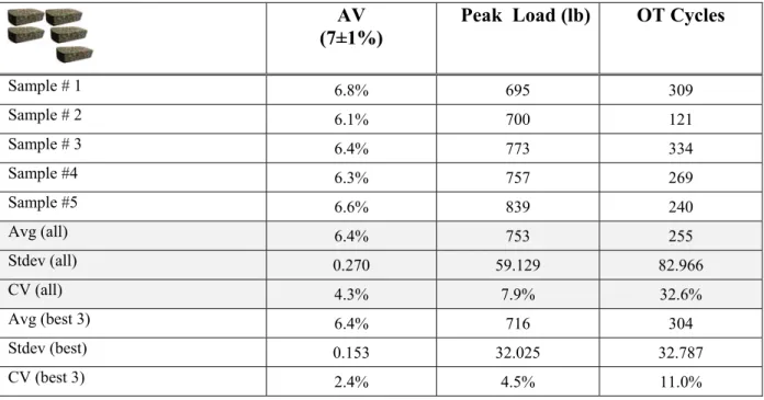
Tex 248-F specification (TxDOT 2011). Analysis of the OT data is typically accomplished using ordinary MS Excel spreadsheets or macros. Table 3-4 shows an example of the OT results obtained after testing samples prepared from the plant mix sampled from US 59 (Atlanta District).
Table 3-4. Overlay Test Results for Type D Plant-Mix from US 59 (Atlanta District, TX). AV
(7±1%)
Peak Load (lb) OT Cycles
Sample # 1 6.8% 695 309 Sample # 2 6.1% 700 121 Sample # 3 6.4% 773 334 Sample #4 6.3% 757 269 Sample #5 6.6% 839 240 Avg (all) 6.4% 753 255 Stdev (all) 0.270 59.129 82.966 CV (all) 4.3% 7.9% 32.6% Avg (best 3) 6.4% 716 304 Stdev (best) 0.153 32.025 32.787 CV (best 3) 2.4% 4.5% 11.0%
3-5
Five replicate samples will be used and results input into the MS Access® Data Storage
System. However, only the best three results with the lowest CV will be used in M-E analysis and/or performance analysis/predictions. Researchers developed an MS Excel macro to do the analysis (i.e., picking the best three) and can be found in the included CD (Walubita et al. 2011).
OT Fracture Properties
To determine the fracture properties (A and n) of the HMA mixes, researchers used the
enhanced OT test procedure for fracture properties (A and n) (Zhou et al. 2010). Appendix B
provides a detailed explanation of the procedure and data analysis method. MS Excel macros for performing the analysis can be found in the included CD. Like the regular OT, five replicate samples will be utilized and entered into the MS Access Data Storage System. The user can then pick the best three, based on the lowest CV using an MS Excel macro (refer to the included CD).
A step-by-step description of the enhanced OT Test procedure for measuring and
computing the fracture parameters, A and n is presented below (Zhou et al. 2010):
• Specimen size is 6 inches (150 mm) long by 3 inches (75 mm) wide by 1.5 inches
(38 mm) high, and it can be cut from a sample prepared on the SGC or from a field core.
• Step 1, OT-modulus (E) test: The OT-E test is carried out using the OT machine with
certain modifications (discussed in detail in Appendix B), to determine the HMA modulus E.
• Step 2, OT test: To determine the fracture properties (A and n), a modified version of
Tex-248-F is used (see Appendix B).
• After performing these two steps, the fracture properties A and n can be calculated using
an MS Excel macro, which is given in the included CD.
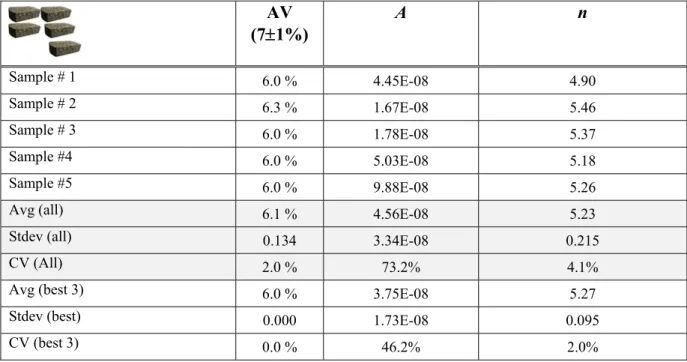
Table 3-5 shows an example of the computed results, and Appendix B has other examples.
Clearly, Table 3-5 shows high variability for the fracture parameter A based on the higher CV
3-6
Table 3-5. OT Fracture Properties Results for Type D Plant-Mix from US 59 (Atlanta District, TX). AV (7±1%) A n Sample # 1 6.0 % 4.45E-08 4.90 Sample # 2 6.3 % 1.67E-08 5.46 Sample # 3 6.0 % 1.78E-08 5.37 Sample #4 6.0 % 5.03E-08 5.18 Sample #5 6.0 % 9.88E-08 5.26
Avg (all) 6.1 % 4.56E-08 5.23
Stdev (all) 0.134 3.34E-08 0.215
CV (All) 2.0 % 73.2% 4.1%
Avg (best 3) 6.0 % 3.75E-08 5.27
Stdev (best) 0.000 1.73E-08 0.095
CV (best 3) 0.0 % 46.2% 2.0%
The Dynamic Modulus (DM) Test
The DM test will be carried out as per the AASHTO TP 62-03 standard test procedure at five different temperatures and six loading frequencies. Analysis and interpretation of the results is also based on the AASHTO TP 62-03 specification (AASHTO 2001), with some analysis
templates given in the included CD. Table 3-6 shows an example of the test results for two temperatures and two loading frequencies, with a master-curve shown in Figure 3-1. Appendix B includes examples of detailed DM test results.
3-7
Table 3-6. |E*| Results for Type D Plant-Mix from US 59 (Atlanta District, TX) AV
(7±1%)
|E*| @ 77°F, 10 Hz (ksi) |E*| @ 130°F, 5 Hz (ksi)
Sample # 1 8.0% 817 48 Sample # 2 7.9% 848 40 Sample # 3 7.3% 875 49 Avg 7.7% 847 46 Stdev 0.379 29.023 4.933 CV 4.90% 3.43% 10.80% 1 10 100 1,000 10,000 0.000001 0.001 1 1000 1000000 M odul us (ks i) Reduced Frequency (Hz) Sample# 1 Sample# 2 Sample# 3 Avg
Figure 3-1. |E*| Master-Curve for Type D Plant-Mix (US 59, Atlanta District).
The Repeated Load Permanent Deformation (RLPD) Test
Researchers used the RLPD test, which is based on TTI Report 0-5798 (Zhou et al. 2010) to determine the HMA permanent deformation properties, namely the viscoelastic parameters
3-8
method are based on the recommendations of Zhou et al. (2010). MS Excel macros for
analyzing the data are provided in the included CD. A step-by-step procedure for the RLPD test and data analysis is described below:
• Specimen size is 4 inches (100 mm) in diameter by 6 inches (150 mm) high.
• Test without confining pressure, with 0.1 second loading and 0.9 second rest period.
• Conduct test at two temperatures (to simulate the Texas climate), 104°F/40ºC and
122°F/50ºC.
• Apply the loads corresponding to each temperature as per Table 3-1(i.e., 20 psi for 104°F
and 10 psi for 122°F).
• To determine the viscoelastic rutting parameters, the accumulative permanent
deformation (or strain) versus the number of load repetitions (N) is plotted on a log-log scale. This is expressed by the classical power law model given in Equation 3-1:
εp = aNb (Equation 3-1)
Where
a = intercept that represents permanent strain at N = 1.
b = slope that represents the rate of change in permanent strain as a function of
the change in load repetitions (log N).
Table 3-7 shows an example of the results obtained from RLPD test and shows that the mu parameter has high variability, particularly at the high temperature. In general and as theoretically expected, variability is often high at the high temperature domain partially due to the increasing elasticity of the HMA mix.
3-9
Table 3-7. RLPD Results for Type D Plant-Mix from US 59 (Atlanta District, TX). Sample Set#1, T=40°C
(20 psi, 10,000 load cycles)
Sample Set#2, T=50°C (10 psi, 10,000 load cycles)
AV (7±1%) Alpha (α) mu (μ) AV (7±1%) Alpha (α) mu (μ) Sample#1 8.0% 0.6436 0.58 7.2% 0.5912 0.31 Sample#2 7.9% 0.6218 0.51 6.9% 0.6872 0.49 Sample#3 7.3% 0.6145 0.50 7.5% 0.7073 0.65 Avg. 7.7% 0.6266 0.53 7.2% 0.6619 0.48 Stdev 0.379 0.015 0.044 0.300 0.062 0.170 COV 4.9% 2.4% 8.2% 4.2% 9.4% 35.2%
The Indirect Tensile (IDT) Test
Both the IDT test and data analysis procedures will be conducted according to Tex-226-F (TxDOT 2011). As shown in Table 3-8, results of the IDT test (Tex-226-F) for samples molded from plant mix sampled from US 59 (Atlanta District, TX) as well as those prepared from raw materials shown in Table 3-8, fall within the typical range of 85–200 psi (TxDOT 2011).
Additionally, the results for both the raw materials and plant mix are comparable and consistent. Table 3-8. IDT Results for Type D Plant-Mix from US 59 (Atlanta District, TX).
AV (7±1%) IDT Strength (psi)
Raw Materials Plant-Mix Raw Materials Plant-Mix
Sample#1 7.3% 7.2% 131 135 Sample#2 7.1% 7.8% 133 129 Sample#3 6.9% 7.8% 136 129 Avg 7.1% 7.6% 133 131 Stdev 0.200 0.346 2.517 3.464 CV 2.8% 4.6% 1.9% 2.6%
Based on the example given, Table 3-8 also shows that the IDT test, which is run in monotonic single-shot loading mode, is very repeatable with CV less than 5 percent. This level
3-10
of variability is not surprising but incomparable with the results shown previously for the
repeated load OT test. Notice also that the samples from the plant-mix exhibited relatively lower IDT strength and higher variability.
HMA Thermal Coefficient
In the improvised TTI test method for the HMA thermal coefficient, changes in the sample dimensions (length) were measured from three radial equidistant points for a temperature
range of 14 to 104°F, changing at a rate of 0.2°F/min. The steps are summarized below:
• Original sample dimensions = 4-inch diameter by 6-inch length or height.
• Measure initial (original) length at room temperature (77°F); average = 6 inches
• Measure the sample length after dropping the temperature to 14°F at a rate of
0.2°F/min.
• Measure the sample length after raising the temperature from 14 to 104°F at a rate of
0.2°F/min.
• Calculate the average change in length to determine the HMA thermal coefficient. The
model for calculating the thermal coefficient was based on the following equation (Apeagyei et al. 2008):
(Equation 3-2)
Where
α = thermal coefficient (in/in/°F).
ε = thermal strain per unit length.
ΔT = change in temperature.
Example test results for the Type D plant-mix from US 59 (Atlanta, TX) are shown in Table 3-9 and are comparable with the data found in the literature (Apeagyei et al. 2008). However, variability as measured in terms of the CV is relatively high, which is partially explained by the fact that there is no direct control of the thermal loading with this test.
3-11
Table 3-9. TTI HMA Thermal Coefficient Results for Type D US 59 (Atlanta District, TX). AV (7±1) α (in/in/°F) Sample# 1 7.4% 1.05E-05 Sample# 2 6.9% 1.92E-05 Sample# 3 7.3% 0.93E-05 Avg 7.2% 1.30E-05 Stdev 0.003 5.40E-06 CV 3.3% 41.5%
The α range found in the literature was 1.137–3.512 E-05, from which the above average
value falls within range (Apeagyei et al. 2008). The MEPDG uses a default α value of 1.300E-05
in/in/°F, which coincidentally, is equivalent to the value shown in Table 3-9. However, as
TxDOT recommended, there is still a need to compare with the Tex-428-A (TxDOT 2011) and then, assess as to which method is more practical with repeatable and realistic results. This is
currently ongoing; but as Table 3-6 shows, the results from the improvised TTI test method are not
unreasonable.
DATA REPORTING FORMAT AND ACCESS
In general, most of the HMA materials test data are reported and/or may be accessed in one or more of the following formats from the MS Access Data Storage System; see Figures 3-2 through 3-5:
• Numerical listing.
• Tabular listing.
• Bar chart.
3-12
Figure 3-2. Hamburg Test Data for US 59 Plant Mix (Atlanta District).
Figure 3-3. Overlay Test Data for US 59 Plant Mix (Atlanta District).
3-13
Figure 3-5. OT Results from US 59 (Atlanta District).
Clearly, Figures 3-2 through 3-5 show that the MS Access Data Storage System has potential to display data in any desired format. Appendix B shows more examples of data extract from the MS Access Data Storage System. Currently, investigations are under way to facilitate direct data exporting from the MS Access Data Storage System or vice versa.
SUMMARY
This chapter presented the data analysis plans for the HMA mixes including the test specifications, analysis procedures, and the data reporting format. Overall, all the data analysis procedures and methods are consistent with the Texas and US national standards for testing, analyzing, reporting, and interpreting the HMA test data, except for the following:
• OT fracture properties.
• RLPD test data.
• HMA thermal coefficient.
Examples of the test results and data extracts from the MS Access Data Storage System were also presented. Test plan proposals for HMA mixes are included in Appendix B.
4-1
CHAPTER 4: LAB TEST DATA ANALYSIS: PART III
Part III of the laboratory data analysis plans pertain to the base and subgrade soil
materials, both untreated and treated. These data analysis plans are discussed in this chapter and include the data collection format, raw data reduction process, and analysis procedure for the untreated and treated base and subgrade materials. The following tests are common among all the treated and untreated bases and subgrade soils:
• Sieve analysis.
• Atterberg limits.
• Soil Classification.
• Moisture density curves.
MATERIAL SAMPLING AND QUANTITIES
At each site, the required materials should be sampled at a minimum of three locations at the test section. For flexible bases the material should be sampled from the windrow. For treated materials, the materials should be gathered before the stabilizing agent is added. For plant-mix treated materials, the material should be sampled from the plant at three distinct locations within the stock pile. Overall, a minimum of 600 lb of material (200 lb per sampling point) should be collected for bases and 450 lb (150 lb per sampling point) for the subgrade soils. TEST SPECIFICATIONS AND DATA ANALYSIS METHODS
Test plan proposals for the base and subgrade soil materials are included in Appendix C.
Sieve Analysis
Materials collected from each location should be subjected to sieve analysis as per Tex 110-E and Tex-111-E (TxDOT 2011). These tests include:
• Dry sieving with the addition of No. #100 and #200 to the sieve stack on the entire
materials retrieved from the site. The values to be reported are percent passing Sieves 2 1/2 in., 1-3/4 in., No. 7/8 in., 3/8 in., No. 4, No. 40, No. 100, and No. 200.
4-2
• Wash sieve on representative samples of adequate weight as described in Tex-110-E.
The values to be reported are percent passing on sieves No. 40, No. 100. and No. 200.
• Hydrometer tests on representative samples using the materials passing No. 40 sieve.
The values to be reported are percent passing 0.02 mm, 0.002 mm, and 0.001 mm.
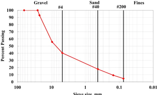
The average gradations from Item 1 should always be compared with what TxDOT reports in the QC/QA charts. If the two gradations on each sieve are within 5 percent for sieves coarser than No. 40 or 3 percent on sieves equal or finer than No. 40, the sampled materials will be considered different. Figures 4-1a to 4-1c show the average gradation from the three tests will be used for subsequent tests.
Figure 4-1a. Typical Average Gradation Curve from an El Paso Base.
0 10 20 30 40 50 60 70 80 90 100 0.01 0.1 1 10 100 P er cent Passing Sieve size, mm #4 #40 #200
4-3 0 20 40 60 80 100 %a ge P assin g Sieve Size Dry Wet #200 #4 #40
Figure 4-1b. Typical Average Gradation Curves for Raw Subgrade Soil (Loop 480, Laredo). 0 2 4 6 8 10 12 14 16 0.001 0.010 0.100 Avg . P er cen t P ass in g (% )
Avg. Grain Diameter (mm)
Figure 4-1c. Hydrometer Test Results for Raw Subgrade Soil (Loop 480, Laredo).
Atterberg Limits
Atterberg Limits tests consist of the Liquid Limit, Plastic Limit, and Plasticity Index tests and are conducted as per Tex-104-E through Tex-106-E (TxDOT 2011). One test will be carried out on the representative sample from the stock for comparison with TxDOT results if available.
4-4
If the two results are different (i.e., the liquid limits differ by more than 15 percent and the Plasticity Index by more than 20 percent), the research team will conduct a second series of tests. It should be mentioned that the treated materials should be also tested once after treatment. Table 4-1 includes the typical results from the test on the material shown in Figure 4-1. The results seem quite repeatable, justifying the reduction in the number of replicates.
Table 4-1a. Typical Index Test Results from an El Paso Base.
Material Properties Sample Avg Stdev COV
#1 #2 #3 Atterberg Limits Tex-104-E LL 22 23 24 23 1.000 4% Tex-105-E PL 13 15 15 14 1.155 8% Tex-106-E PI 9 8 9 9 0.577 7%
Table 4-1b. Typical Index Test Results for Raw Subgrade Soil (Loop 480, Laredo).
Material Properties Sample Avg Stdev COV
#1 #2 #3 Atterberg Limits Tex-104-E LL 15 15 16 15 0.577 3.8% Tex-105-E PL 10 11 10 10 0.577 5.6% Tex-106-E PI 5 5 6 5 0.577 10.8% Soil Classification
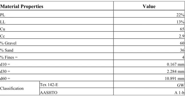
The average results from the sieve analysis and the Atterberg Limits should be used to classify the materials as per Unified Soil Classification System and AASHTO Classification System. The supporting information that should be extracted is percent gravel, percent sand, and percent passing No. 200. In addition, the Coefficients of Uniformity (Cu), and Coefficient of Curvature (Cc), should be calculated by estimating and reporting the diameters associated with
10 percent, 30 percent, and 60 percent passing, d10, d30 and d60, respectively. Table 4-2 shows an
4-5
Table 4-2. Typical Results for Soil Classification of an El Paso Base.
Material Properties Value
PL 22% LL 13% Cu 65 Cc 2.9 % Gravel 60 % Sand 36 % Fines = 4 d10 = 0.167 mm d30 = 2.284 mm d60 = 10.891 mm
Classification Tex 142-E GW
AASHTO A 1-b
Moisture Density Curves
The next step is to perform a moisture density test as per Tex-113-E for the bases and Tex 114-E for the subgrade soils. Four specimens at different moisture contents are prepared. For treated materials, the design dosage of the stabilizer will be added to the material. The reported outcomes of these tests are the optimum moisture content (OMC) and the maximum dry density (MDD). The results from one series of tests should be compared with those from TxDOT (if available). If the two results are different (i.e., the two OMCs differ by more than 1 percent and the MDD by more than 2 pcf), the researchers will conduct a second set of tests. Table 4-3 shows typical results from such an activity on an El Paso base. The results are quite repeatable, suggesting that replicate tests may not be necessary.
Table 4-3. Typical Moisture Density Test Results from an El Paso Base.
Material Properties Samples Average Stdev COV
#1 #2
MDD (pcf) 144 145 145 0.707 0%
4-6 11.80% 104.0 106.0 108.0 110.0 112.0 114.0 116.0 118.0 120.0 5% 7% 9% 11% 13% 15% 17% Dr y De ns ity (p cf ) Moisture Content MDD 117 pcf OMC 11.8%
Figure 4-2. Example of MD for Raw Subgrade Soil (Loop 480, Laredo).
Strength Tests on Untreated Bases and Subgrades
The strength tests that are necessary for the untreated materials include the Texas Triaxial Tests (Tex-117-E) and Standard Triaxial Test (Tex-143-E) (TxDOT 2011). These tests are described below.
The Texas Triaxial Tests
The Texas Triaxial tests will be performed on six specimens prepared at the OMC and MDD and moisture conditioned for 10 days. The specimens will be subjected to six confining pressures varying between 0 to 15 psi, as described in Tex-117-E. The values to be reported are
the angle of internal friction, φ, cohesion, c, and the classification, TTC. As the results of these
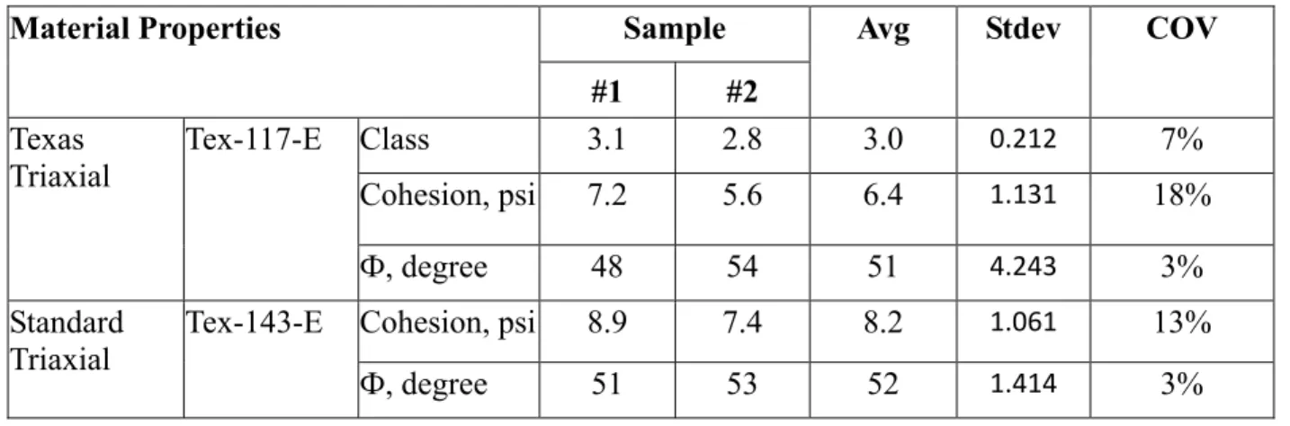
tests are less critical to the design, they will be carried out on one set of specimens. Table 4-4 shows the typical results on two sets of specimens. The variations between the Texas Triaxial Class and the angle of internal friction are rather small. The higher variation in the cohesion can be attributed to the small values associated with them and the nature of curve fitting associated with these tests.
4-7
Table 4-4. Typical Results from Strength Tests on an El Paso Base.
Material Properties Sample Avg Stdev COV
#1 #2 Texas
Triaxial Tex-117-E Class 3.1 2.8 3.0
0.212 7%
Cohesion, psi 7.2 5.6 6.4 1.131 18%
Ф, degree 48 54 51 4.243 3%
Standard
Triaxial Tex-143-E Cohesion, psi 8.9 7.4 8.2
1.061 13%
Ф, degree 51 53 52 1.414 3%
The Standard Triaxial Tests
The Standard Triaxial tests will be performed on three specimens prepared at the OMC and MDD. These specimens are tested about 24 hrs after preparation without moisture
conditioning. The specimens will be subjected to three confining pressures varying between 3 to
10 psi, as described in Tex-143-E. The values to be reported are the angle of internal friction (φ)
and cohesion (c). This test will be carried out on two sets of specimens. If the results from the two sets are different (i.e., the angles of internal friction differ by more than 10 percent or the cohesions by more than 20 percent), a third set of tests will be performed. Table 4-4 shows typical results on two sets of base specimens. This test seems to be slightly more repeatable than the Texas Triaxial Tests.
Strength Tests on Treated Bases and Subgrades
The unconfined compressive strength (UCS) test will be carried out on the bases and subgrade soils that are treated with stabilizers in triplicate. Researchers at the OMC and MDD will prepare three specimens with the design dosage of stabilizer, then cure these for seven days before testing. The test protocol in general is similar to that of Tex-117-E. The reported values are the individual and average values of the UCS as well as corresponding COV.
4-8
Deformation Tests on Untreated Bases and Subgrades
The deformation tests that are necessary for the untreated materials include the resilient modulus (MR) tests and the permanent deformation (PD) tests. These tests are described below. Resilient Modulus Tests
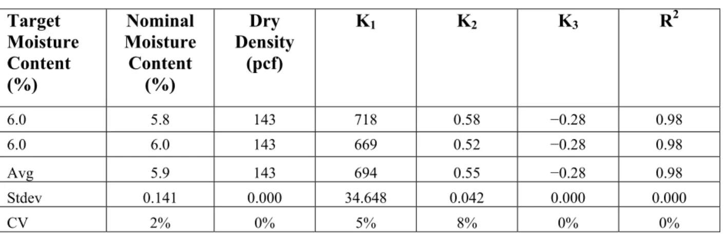
The resilient modulus tests will be performed as per NCHRP 1-28A procedure as included in Appendix C. The parameters to be reported for each specimen are the three fit
parameters (k1 through k3) and the coefficient of correlation (R2) values of the best fit curve.
These tests will be carried out in duplicate on specimens prepared at the OMC and MDD. If the results from the two resilient modulus tests (as the representative modulus values judged at representative confining pressure and deviatoric stress as the MEPDG prescribed) differ by more than 20 percent, a third test will be performed. Table 4-5 shows an example for the El Paso base.
Table 4-5. Typical Results for Resilient Modulus Parameters on El Paso Base. Target Moisture Content (%) Nominal Moisture Content (%) Dry Density (pcf) K1 K2 K3 R2 6.0 5.8 143 718 0.58 −0.28 0.98 6.0 6.0 143 669 0.52 −0.28 0.98 Avg 5.9 143 694 0.55 −0.28 0.98 Stdev 0.141 0.000 34.648 0.042 0.000 0.000 CV 2% 0% 5% 8% 0% 0%
Permanent Deformation Tests
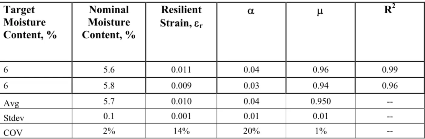
The permanent deformation tests will be performed as per procedure included in Appendix C. The parameters to be reported for each specimen are the resilient strain, εr,
permanent deformation parameters α and μ and the R2 values of the best fit curve. These tests
will be carried out in duplicate on specimens prepared at the OMC and MDD. If the results from
the two PD tests (as judged by the parameters α and μ) differ by more than 20 percent, a third
4-9
Table 4-6. Typical Permanent Deformation Parameters for El Paso Base Material. Target Moisture Content, % Nominal Moisture Content, % Resilient Strain, εr α μ R2 6 5.6 0.011 0.04 0.96 0.99 6 5.8 0.009 0.03 0.94 0.96 Avg 5.7 0.010 0.04 0.950 -- Stdev 0.1 0.001 0.01 0.01 -- COV 2% 14% 20% 1% --
Deformation Tests on Treated Bases and Subgrades
The deformation tests that are necessary for the treated materials include modulus tests and the permanent deformation (PD) tests. These tests are described below.
Modulus Tests
The resilient modulus (MR) tests will be performed similar to the untreated materials but
at zero confining pressure. The deviatoric stresses applied to the specimens will be 10 percent, 20 percent, 30 percent, and 40 percent of the UCS of the material determined before. Three specimens with the design dosage of stabilizer will be prepared at the OMC and MDD and will be cured for seven days prior to testing. The parameters to be reported for each specimen are the
representative resilient modulus since parameters k2 and k3 will be zero for these materials.
Figure 4-3 shows an example for the El Paso base.
As part of this activity, free-free resonant column (FFRC) tests will be performed on each
specimen before MR tests. According to Hilbrich and Scullion (2007), these tests are more
robust and repeatable than the MR tests. The moduli from the FFRC and MR tests will be
4-10
0
100
200
300
400
500
600
700
0
50
100
150
200
250
R
es
ilie
n
t M
od
u
lu
s
(k
si)
Deviatoric Stress (psi)
10%
20%
30%
40%
k
1=32686
RM= 480 ksi
FFRC Modulus =1097 ksi
Figure 4-3. Typical Resilient Modulus Test Results.
Permanent Deformation Tests
The permanent deformation tests will be carried out only if the percent stabilizer is less than 2 percent as per procedure included in Appendix C. The parameters to be reported for each
specimen are the resilient strain, εr, permanent deformation parameters α and μ, and the R2
values of the best fit curve. These tests will be carried out in duplicate on specimens prepared at
the OMC and MDD. If the results from the two PD tests (as judged by the parameters α and μ)
differ by more than 20 percent, a third test will be performed.
Moisture Characteristics Tests
The moisture characteristics tests include the establishment of soil water characteristic curves of untreated bases and subgrade soils. In addition, since the specific gravities of these materials are also needed to establish the volumetric moisture contents, these values will also be measured.
4-11 Soil Water Characteristic Tests
These tests will be carried out using the filter paper method as described by Bulut et al. (2001). The results reported are the variations in the soil matric suction, ψ, with volumetric
moisture content, θ. One of the models that will be considered to fit to the measured data is,
(Equation 4-1)
Where
ψr = matric suction at residual volumetric water content.
θsat = volumetric water content at full saturation.
α, n, m = the model fitting parameters.
These tests will be conducted on one sample at different moisture contents.
Specific Gravity Tests
To assess the degree of saturation, hence the volumetric moisture content at saturation,
the specific gravity of the material, Gs, should be known since the degree of saturation, Sr, is
estimated from the gravimetric moisture content, ω, using the equation,
Sr = ω Gs ρd/( Gsρw – ρd) (Equation 4-2)
Where
ρd = dry mass density.
ρw = mass density of water.
The specific gravity of the bases will be estimated as per ASTM C-127 and C-128, while the specific gravity of the subgrade soils will be estimated from Tex-108-E. Due to the
uncertainties in the measurement of the specific gravity and the narrow range of specific gravity that most bases and subgrade soils fall within, it is not uncommon to estimate this value.
4-12
In this study, these tests will be carried out in duplicate on several materials. Based on the evaluation of these results, a decision on reducing the number of tests or eliminating them will be made. Table 4-7 is an example of the specific gravity results for the raw subgrade soil from Loop 480 in Laredo District.
Table 4-7. Specific Gravity Results for Raw Subgrade Soil (Loop 480, Laredo).
Item Specific Gravity
Sample# 1 2.57 Sample# 2 2.62 Sample# 3 2.60 Avg 2.60 Sdtev 0.02 CV 0.94% SUMMARY
This chapter discussed the data analysis plans for the base and subgrade soil materials, both untreated and treated. Criteria for material sampling, test procedures, and data analysis methods/models along with the data reporting format were all discussed. Test plan proposals for the base and subgrade soil materials are included in Appendix C.
5-1
CHAPTER 5: FIELD TEST DATA ANALYSIS: PART I
The data analysis plans discussed in this chapter pertain to the field tests that were recommended to evaluate some of the key distresses and performance characteristics of the HMA flexible pavements and overlays. As discussed here, Part I of these data analysis plans includes the following:
• Test section characteristics.
• Crack survey.
• Rutting.
• Surface profiles.
• Skid number.
The data analysis plans also include descriptions of theparameters to be measured, test
methods, test equipment, target number of sections to be tested per year, frequency of tests, proposed time of the year, and example of the data collected. A summary of key points is then presented to conclude the chapter.
TEST SECTION CHARACTERISTICS
As per TxDOT recommendation, researchers will use one 500-ft test section per
homogeneous highway project and homogeneous pavement structure, preferably in the outside lane. Figure 5-1 shows that the selection of the test sections will be conducted in conjunction with Study 0-6622 subject to TxDOT approval. To ensure that all influencing variables are accounted for, the factors listed in Table 5-1 will be considered when selecting the test sections.
In summary, the test sections should not, for instance, be only Overlays or new
construction. The coverage should be as broad as possible to cover all the factors in Table 5-1. Otherwise, it will be very difficult to calibrate the M-E models. So, it is very critical that the researchers ensure that the 100 test sections, if possible, cover an equal number of variables listed in Table 5-1, including the associated distresses as Study 0-6622 (2011) stipulates.
5-2
Researchers (and/or District) nominate Hwy sections
Step 1
Researchers collect all available existing data.
Step 2
Researchers submit to
Study 0-6622
for
review/comments..
Step 3
Researchers submit to
PD/PMC
for review/approval
Step 4
If
APPROVED
, Researchers can then proceed with with
entry in Master Table &
Data Collection
...
Step 5
Figure 5-1. Steps for Selecting Field Test Sections.
Table 5-1. Variables to Consider when Selecting Test Sections.
# Variable Minimum Description Comment
1 Pavement type 4 a) HMA on HMA, b) HMA on untreated granular bases, c) HMA on treated base, and d) surface treatment on untreated and/or treated base.
WMA, RAP, RAS, and perpetual pavements will also be considered. 2 Pavement
category 4 a) perpetual, b) typical flexible HMA, c) HMA overlay over HMA, and d) HMA overlay over PCC
3 Thickness 2 a) thin (≤ 3 inches) and b) thick (> 3 inches)
4 Traffic levels 2 a) low and b) high volume Include Intestate, State, and Farm roads 5 Environmental
types 5 a) dry-warm, b) dry-cold, c) wet-warm, d) wet-cold, and e) moderate (mixed). 6 Age conditions 2 a) new construction and b) existing
5-3
In cases where the pavement structure is homogeneously the same, but other variables such as traffic or age are different, then more than one different 500-ft test sections may be utilized from such a highway project. For instance, if the pavement structure such as the number of layers, layer thicknesses, or materials on the same highway is different, then more than one 500-ft test sections may be utilized. Examples of these scenarios include the following:
• SH 114 (Fort Worth District)—same traffic level, environment, and perpetual pavement
structure but two different materials. Two test sections were thus selected: one with SFHMA mix designs, and the second with traditional dense-graded mix designs.
• US 59 (Atlanta District)—same traffic level and environment but different overlay
structures: one with Petromat interlay, another with Truepave interlayer, and the third, without any interlayer material (denoted as Control). Therefore, three test sections were selected representing Petromat, Truepave, and Control, respectively.
To ensure homogeneity when selecting the test sections, particularly in the case of the existing pavement structures and overlays, both the GPR and FWD will be utilized to locate homogeneous sections. Once a test section has been identified, the start and end points are marked using the following identifiers:
• Painting (white or orange paint) on the shoulders—test section start and end points.
• GPS coordinates—test section start and end points.
• Existing mile marker signs—test section start and end points.
• Physical landmarks such as intersections, etc.—test section start and end points.
• Road signs—at test section start and end points; see Figure 5-2.
Once marking of the test sections is completed, field testing can then be conducted. Table 5-2 lists the test procedures and data characteristics for cracking, rutting, surface profiles, and skid number; see Appendix D for more details.
5-4
Figure 5-2. Road Signs for the Test Sections.
Table 5-2. Field Test Procedures and Data Characteristics—Part I. # Test Test Procedure
(Spec) Frequency Analysis Method Output Data (Units)
Typical Value/ Threshold
1 Cracking Visual-walking surveys (manual counts and tape measurements) −Alligator cracking −Longitudinal cracks
−Transverse cracks At test section selection and/or just after construction, and thereafter, twice per year (just after winter and summer) MS Excel Number of cracks; %age cracking; crack length, interspacing of cracks, crack width (severity), crack density ≤ 25% (alligator) ≤ 1000 ft/mi (longitudinal) 2 Surface
rutting Straightedge, wedge, and ruler; ≥ 6 pts @ 100 ft interval; both WPs
MS Excel Rut depth
(inch) ≤ 0.5
3 Surface
profiles TTI high-speed profiler; in both WPs TxDOT RideQuality Software
IRI (inch/mi)
and PSI 30 ≤ IRI≤ 172; 2.5 ≤ PSI ≤ 5.0 4 Texture
and skid
From TxDOT PMIS From TxDOT PMIS
From TxDOT PMIS