Nexus
LX
Contents
1. Introduction to Nexus 1
1.1 Disclaimer...1
1.2 About the Nexus System ...1
1.3 Nexus Through-Life Support...3
2. Nexus System Design Sequence 5 2.1 Check the Data Cabling Standard...5
2.2 Check the Data Cable ...5
2.3 Plan the SPU Locations ...5
2.4 Plan the Channel Routes...6
2.5 Plan the Router and Repeater Locations and the Trunk Route ...6
2.6 Plan the Terminator Locations...7
2.7 Number the Channels and Apply Channel Sequences...7
2.8 Plan the Nexus Server Location ...8
2.9 Mark up Drawings with Details...8
2.10 Check your Work...9
2.11 Create the Materials List ...9
2.12 Create the Project Specifications ...9
3. Nexus User Guide 11 3.1 The Nexus Program ...11
3.2 SPU Type and Status ...16
3.3 Using Groups...18
3.4 Emergency Lighting Tests ...20
3.5 Reports...23
3.6 Integrity Monitor ...23
3.7 Maintenance ...24
3.8 Nexus Network Management ...25
3.9 Nexus Database ...29
4. Network Utility User Guide 31 4.1 Network Utility Program ...31
4.2 Commissioning the NUN ...31
4.3 Discovering Nodes ...32
4.4 Getting Info from Nodes in the Table...32
4.5 Sorting, Saving and Retrieving Node Tables...32
4.6 Setting Routers and Repeaters Online/Offline...33
4.7 Packet Counting Nodes ...33
4.8 Identifying Nodes ...34
4.9 Discovering Hidden Nodes...34
4.10 Shutting Down the NUP ...35
5. Installation Guide 37 5.1 Data Cable Connection ...37
5.2 Data Communications ...40
5.3 Testing Data Communications ...43
ii Nexus LX
5.5 Installation List ... 47
6. Commissioning Guide 49 6.1 Before you Begin ... 49
6.2 Purpose of Commissioning ... 49
6.3 Nexus Device Credits ... 49
6.4 Commissioning the Nexus System ... 50
6.5 Nexus Error Messages ... 52
6.6 SPU LED Colour Meanings... 55
7. Sample Consultant Specifications 59 7.1 Emergency Light Fittings ... 59
7.2 Data Network... 59
7.3 Computer Hardware... 60
7.4 Computer Software ... 60
7.5 Communications ... 60
7.6 System Programming and Commissioning... 61
8. Glossary of Terms 63
1.
Introduction to Nexus
Nexus is a real-time Emergency Lighting monitoring and control system. It enables its users to
manage an entire installation – installing and removing components, testing and monitoring the system and managing maintenance activities.
In This Chapter
Disclaimer ... 1 About the Nexus System ... 1 Nexus Through-Life Support ... 3
1.1 Disclaimer
All information and recommendations are, to the best of our knowledge, accurate at the time of writing. All trademarks and trade names, registered or not, are the property of their respective owners. All specifications are subject to change without notice.
More information is available on our website: http://www.tnbaust.com
1.2 About the Nexus System
A basic Nexus network consists of a trunk with one or more branches with level 4 shielded twisted pair data cable as the transmission medium. The branches are generally referred to as channels. Each channel is connected to the trunk by a router. The only nodes that can be connected to the trunk are the Nexus Server, the Network Utility Node and the routers that connect the channels. SPUs cannot be connected to the trunk.
2 Nexus LX Both the trunk and the other channels may be extended by using repeaters. Where a channel has been extended using a repeater, the channel is thereby broken up into channel segments. Each channel segment consists of a length of data cable with nodes connected along the length of it and with the two ends terminated with data cable terminators (commonly referred to as “end-of-line resistors”). This connection configuration is known as a “doubly terminated multi-drop bus”.
Figure 1: Basic Nexus Network
A Nexus Network consists of the following hardware components:
1 Nexus Single Point Units (SPUs: NXS Quickfit, NXS Spitfire, NXS Powerpack, NXS Flood etc)
2 Routers 3 Repeaters 4 Nexus Server
5 Network Utility Node (NUN) 6 Data Cable Terminators 7 Data Cable
1.3 Nexus Through-Life Support
If you require further assistance, telephone the Stanilite National Support Centre in Australia as listed below.
1300 666 595 T 1300 666 594 F
http://www.tnbaust.com
Trademarks
All TRADEMARKS mentioned in this manual are the property of their respective owners. Nexus, Quickfit, Spitfire and Stanilite are Trademarks of Thomas & Betts Australasia Pty Ltd. ECHELON, LONWorks, LONTalk and Neuron are Trademarks of ECHELON Corporation. CYPRESS and TOSHIBA are the Trademarks of their respective companies.
MICROSOFT, MS-DOS, and WINDOWS, are Trademarks of MICROSOFT Corporation.
Nexus LX MANUAL Ver2 issued 20/03/2010.
2.
Nexus System Design Sequence
Plan the Nexus system before you attempt to install any components. This chapter guides you through the planning process.
In This Chapter
Check the Data Cabling Standard ... 5
Check the Data Cable... 5
Plan the SPU Locations... 5
Plan the Channel Routes ... 6
Plan the Router and Repeater Locations and the Trunk Route ... 6
Plan the Terminator Locations ... 7
Number the Channels and Apply Channel Sequences ... 7
Plan the Nexus Server Location ... 8
Mark up Drawings with Details ... 8
Check your Work ... 9
Create the Materials List ... 9
Create the Project Specifications... 9
2.1 Check the Data Cabling Standard
In situations where the Nexus server will be connected to the Public Switched Telephone Network (PSTN) via a modem or some other device, it will be necessary to install the Nexus data cable in accordance with the AS/ACIF S009 cabling standard and this must be done by a registered cabling provider.
The intent of the AS/ACIF S009 standard is to enforce a minimum separation between mains and data circuits for data networks that are, or are intended to be, connected to the PSTN. This requirement should be clearly listed in the project specification. Further information on this can be obtained by contacting either ACIF (Australian Industry Communications Forum) or the ACA (Australian Communications Authority)
2.2 Check the Data Cable
The data cable used to install Nexus networks should be the standard Stanilite yellow Nexus cable. This is a level 4 shielded 22AWG stranded single twisted pair cable – part number NXS-1PS. If it is necessary to use an alternative cable, contact Stanilite for detailed advice.
2.3 Plan the SPU Locations
This Guide does not cover information contained in AS/NZS 2293.
C
H A P T E R2
6 Nexus LX Locate the fittings so that they comply with AS/NZS 2293 and are easily installed and maintained. Mark up the plans to indicate the location of every node.
2.4 Plan the Channel Routes
There are two types of limitations when it comes to determining how to connect Nexus SPUs to form a network. The cabling limit is imposed by the electrical loading of a node on a length of data cabling. The addressing limit is imposed by the digital addressing mechanism of the communications protocol.
Nexus Cabling Limits
Within a single channel segment there must be 50 nodes or less over a cable length of 1000m. If a channel must be longer than this or have more nodes than this, the channel can be sub-divided into segments using repeaters. Each channel segment is subject to the cabling limit.
Nexus Addressing Limits
Within a single channel (or trunk) there must be no more than 127 nodes. This number includes any routers or repeaters on that channel.
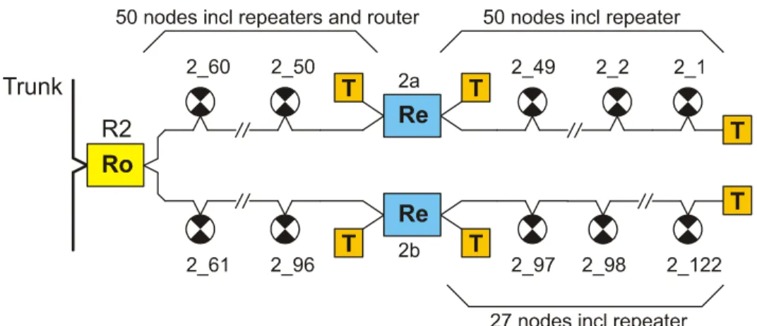
The SPUs marked on the plans must be connected to a channel within the constraints of the cabling and addressing limits. Figure 2 (following) is an example of how it is possible to connect the maximum number of nodes to a channel by using repeaters.
Figure 2: Example of the Maximum Number of Nodes connected to a Channel
2.5 Plan the Router and Repeater Locations and the Trunk
Route
Somewhere along each Channel, there must be a Router connecting it to the Trunk (not necessarily at the end of the Channel).
Repeaters are usually located at the end of channel segments. Note that it is possible to connect a repeater to the middle of a channel segment, but the Nexus Software channel map display will not display this accurately so it is best to avoid this topology if possible.
are generally located in communications rooms or cabinets. Ensure that there is a GPO within reach of each. Note that up to 5 routers/repeaters can be run from the one plug pack power supply if they are mounted adjacent to each other.
The data cable route for both trunk and channels should be marked on the plans, showing the sequence of connection to routers, repeaters and SPUs. This information is vital for maintenance of the system. The as-built version of the plans must be updated to reflect the actual location of the data cable together with the connection sequence.
Do not put data cabling on top of removable ceiling tiles where the movement of the tile could damage it. Do not run the trunk through tenancy areas, where renovations could damage it. Run it through the common areas of the building, and install it to minimise the risk of damage. Dedicated communication cable trays or risers are best.
2.6 Plan the Terminator Locations
A terminator is a passive device which, when connected to the end of a high speed data cable, prevents unwanted distortion of the electrical signal that would otherwise be introduced by the change in characteristic impedance at the end of the cable. Both ends of every channel segment, including the trunk, must be terminated. Mark the location of both ends of every channel segment on the plans. If an SPU is located at the end of a channel segment, then the terminator is usually connected to the data cable within this fitting.
Routers and repeaters are frequently located at the end of a channel segment. They both contain two built-in switch-selectable terminators that can be used in place of a discrete terminator when required. The NUN also contains a switch-selectable terminator. If these nodes are not at the ends of their respective channel segments then the terminators must be switched off.
2.7 Number the Channels and Apply Channel Sequences
This section explains how to number the channels and apply channel sequence numbers to all nodes.
Numbering the Channels
Number the Channels in sequential order from one end of the Trunk to the other. The Trunk is always Channel 1, so the first channel is Channel 2. Each router is numbered according to the channel it connects to i.e. R2 for channel 2, R3 for channel 3 and so on. Each repeater is numbered according to its channel e.g. two repeaters on the trunk would be numbered 1a and 1b while three repeaters on channel 2 would be numbered 2a, 2b and 2c.
If a new Channel is added in the future the numbering may become out of sequence. You can prevent this happening if you are aware of possible future expansion by reserving one or more Channel numbers. However, if the numbering does become out of sequence it will not prevent Nexus from operating correctly. The software does not require that Channel numbering correspond with the network’s physical layout.
Numbering the SPUs
Nexus uses two numbers to represent each SPU: the Channel Sequence Number and the SPU_ID. The Channel Sequence Number consists of two parts, the first identifying the Channel, the second identifying the node’s position on the channel (i.e. the connection order along the data cable).
8 Nexus LX Mark a Channel Sequence Number on the plan adjacent to the symbol for each node. Start at one of the terminators and number in sequence along each channel. Reserve numbers if you know where nodes will be added later. Each number must be unique. Refer to Figure 2 for an example of how to apply channel sequence numbers to the SPUs in a channel. When the time comes for the SPUs to be registered using the Nexus software, it will be necessary to register the SPUs in their channel sequence. In the event that extra nodes have to be inserted at the time of registration, Nexus has a facility for inserting new numbers in a sequence.
The Channel Sequence Number is designed to make maintenance of the communications network easier. In the event of a cable break the Nexus software will only be able to display the location of the break if the channel sequence numbers have been correctly applied.
The Consultant Specification should include a requirement that the installing contractor physically labels all emergency fittings with their Channel Sequence Number and all Routers and Repeaters labelled with their number.
2.8 Plan the Nexus Server Location
The Nexus Server can connect to the network anywhere along the trunk. It is usually placed in a secure and protected location such as a maintenance or security office. If the Server must be located in an area that is exposed or is not secure, then it would be advisable to specify an appropriate housing or computer case configuration. Contact Stanilite for more advice. The NUN is usually located near the server although it can also connect to the network anywhere along the trunk. Mark the location of these nodes on the plans.
2.9 Mark up Drawings with Details
Trunk Cable Route
Draw the cable route on the plans as a line running from router to router. Indicate the location on the trunk of the Nexus Server and the NUN.
Channel Cable Routes
Draw the cable route on plans as a line running from node to node.
The exact cable route can be left up to the installer who should update the “as-installed” plans
accordingly.
Routers
Draw a box containing “R” and the channel number eg:
Repeaters
Draw a box containing “Rpt” and the repeater number eg:
Channel Terminators
Nexus Server
Draw a box containing “PC” eg:
NUN
Draw a box containing “NUN” eg:
2.10 Check your Work
Check that the drawings show:No more than 50 nodes and 1000 metres of data cable per channel segment No more than 127 nodes per Channel (including Routers and Repeaters)
Channel Sequence Numbers
Trunk and Channel Data Cable routes
2 Terminators per Channel Segment 1 Router per Channel
2.11 Create the Materials List
Create a materials list to enable potential installers to quote during tendering for the supply of equipment.
8 Calculate the required quantity of:
SPUs – NXS Quickfits, NXS Spitfires, NXS Powerpacks, NXS Floods etc
Terminators (note that 2 external terminators are supplied with each router and repeater – there should be no need to order extra terminators)
Routers (1 per Channel) Repeaters (where required)
9 Include one Nexus Server package per Nexus network – this will include the Server PC, network interface card, Nexus software and a Network Utility Node. (Other combinations are available – contact Stanilite for details.)
2.12 Create the Project Specifications
You should have completed plan drawings showing the:Location of the SPUs
Individual Channel Sequence Number of every SPU Channel routes
Router, Repeater and Terminator locations Trunk route
Nexus Server location.
GPOs for the Nexus Server and equipment, Routers and Repeaters.
10 Nexus LX
Specifications (shown on page 59).
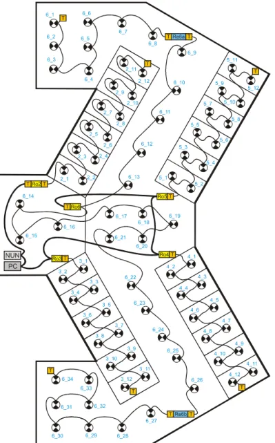
The following figure shows the trunk with the NUN, Nexus server PC and routers. The routers are shown with terminators turned on or off as appropriate.
Channel 6 is shown with 2 repeaters. The SPUs are shown with their Channel Sequence number.
Figure 3: Sample Typical Shopping Centre Layout
If you require further assistance, telephone the Stanilite National Support Centre (see "Nexus Through-Life Support" shown on page 3).
3.
Nexus User Guide
This chapter provides information that is needed to operate a Nexus installation safely and efficiently.
In This Chapter
The Nexus Program... 11
SPU Status... 16
Using Groups ... 18
Emergency Lighting Tests ... 20
Reports ... 23
Integrity Monitor ... 23
Maintenance ... 24
Nexus Network Management... 25
Nexus Database ... 29
3.1 The Nexus Program
This section provides information about starting the Nexus program, using it, and understanding information that it provides.
12 Nexus LX
Starting Nexus
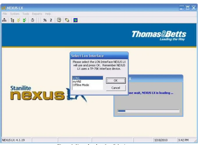
To start Nexus, double-click the NEXUS LX icon on the desktop or select Start | Programs | NEXUS LX | When Nexus is started, it displays Lonworks Network Interface Selection form. Select the correct network interface for normal operation or Offline Mode for no communication, local database only operation.
Figure 4: Nexus Lon Interface Selection
Nexus LX System Information
When Nexus is started, a System Information window pops up. This window provides a summary of the system status. It can be shut down or minimised at any time by using the icons in the top right hand corner. It can be restarted from the main Nexus window by selecting System | Information.
Changing the Installation Name
To change the name of the installation, select System | Set Name then enter the installation name. The name will thereafter appear in the title bar of the Nexus window and in the heading of all reports. Press OK to save the new name.
Closing Nexus
Nexus is a real time monitoring and control system – the Nexus program and Nexus Server are designed to be run 24 hours, seven days per week. If the program is shutdown then the status of the SPUs cannot be observed and any scheduled emergency lighting tests will not be carried out.
However, shutting down Nexus has no effect on the functioning of the SPUs themselves. When Nexus is started again, the status of the nodes can be polled and the system will be current again.
Nexus must be running for the scheduled discharge tests to be carried out
To close Nexus, select File | Close or the button.
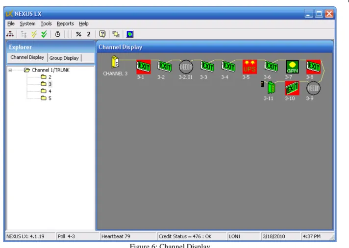
Channel Display
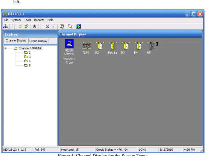
After Nexus started, it displays its main window. There are two display alternatives: Channel Display and Group Display. The Channel Display is a diagrammatic representation of one channel. When the program is started, the default channel is the trunk. The intention of the Channel Display is to show each of the nodes in correct sequence as they are connected along the channel. The channel display is only correct when the nodes are commissioned in their correct sequence. The trunk is displayed as if the Nexus Server and NUN are connected at one end of the channel – this may not be the case in fact.
14 Nexus LX To display a particular channel click the folder symbol for that channel in the Explorer panel on the left.
Figure 6: Channel Display
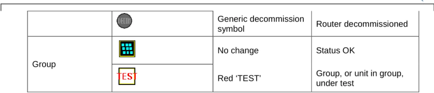
Nexus Node Icons
Nexus uses an icon to represent each different type of node. Any change in the status of a node is indicated by changing the appearance of its icon, as described in the table below.
Component Sample Icons Icon Colour Meaning
No Change Status OK
Red background Unit faulty
Red dot Unit under test
Greyed out Unit not communicating
Lamp greyed out Mains powered lamp out SPU Generic decommission symbol SPU decommissioned Or reserved Router / Repeater No change Status OK
16 Nexus LX Generic decommission
symbol Router decommissioned
No change Status OK
Group
Red ‘TEST’ Group, or unit in group, under test
Node Box
If you double click a node icon, or right click and select Properties from the pop up menu, the node box for that node will appear. The node box lists all the properties and real time data relating to that node and provides access to all the tools that can be used on that node.
The page tabs of node box vary depends on what type of the node is. For example, a MQF, an EFN or GPN all have some of the page tabs different because of their different functionalities. Figure 7 shows a node box for a MQF fitting.
Figure 7: Node Box - Status tab
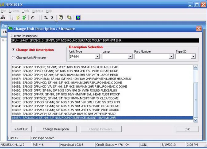
3.2 SPU Type and Status
SPU Type ID and SPU Status number are two important data in the operation of the SPU node. SPU Type ID is a number which defines the description of the SPU node. For example, Type ID = 16467, its SPU description is “S/F NXS ROUND SURFACE MOUNT 10W N/M 2HR”. For every SPU node in NEXUS LX system they must have a Type ID. The correct Type ID value can be entered
by fittings manufacture, technicians during the SPU commissioning process or user at any later stage after the SPU is commissioned. You can change the SPU’s Type ID (fitting’s description) at any time. Figure 8 is used for Type ID change: Node box|Tool Tab|Change Unit Description & Firmware. By default the user does not have the authority to change SPU’s firmware.
Figure 8: Change SPU Description Form
SPU Status is a number to reflect the health of SPU operation. Status number is either polled or returned from the node. This number is interpreted in a way that depends on the Type ID (SPU description) of that node – so it is important that the node has the correct description. Node box Status tab displays the current status for that node. If the status number is not normal, then the state is decoded and interpreted by the software and Possible Faulty Components will be listed on the page. On the Channel display, a faulty status will cause the SPU icon has a red background.
Update Status
Nexus operates in real-time and maintains an internal record of the current status of all the nodes on the network. If the Server has been off or disconnected and therefore unable to receive status updates from the nodes, then it is possible to perform a Status update to refresh the information in the database. If this is not done manually then the Server will after some time update all the information
automatically (see "Integrity Monitor" shown on page 23).
To perform a status update on:
Every fitting in the network Double-click the Nexus Server icon, then on the Nexus Server tab, select Poll Status
18 Nexus LX
All the nodes on a channel Double-click the channel (router) icon, then on the Status tab, select Update Status
All the nodes in a group Double-click the group icon, then on the Tools tab, select
Update Status
An individual fitting Double-click the fitting’s icon, then on the Tools tab, select
Update Status
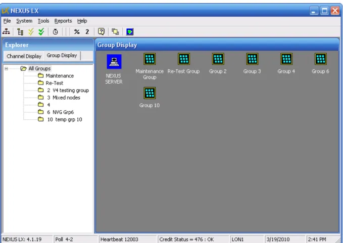
3.3 Using Groups
Grouping is a feature of Nexus that allows some SPUs belong to different channels to be grouped together as one group. For example, Group 101 may contain SPUs like 3-10, 7-34, 12-3 etc. When a SPU is commissioned its default group number is its channel number. For example, the SPUs on Channel 2 will be put into Group 2, and so on. Any SPU can be placed into any Group at any time. However, a SPU can only belong to one Group at a time. The only exception to this is when faulty units are placed in the Maintenance Group.
The scheduled discharge test can only be carried out by a group or groups, not by channels.
Figure 9: Group Display
Creating a Group
Apart from those default groups created during the channel commissioning process, any additional groups can be created at any time.
To create a Group, select the Group Display tab and select Tools | Add/Edit Group. The Add/Edit Groups dialog box will pop up. Enter the Group Number and Group Name and press Add. This creates an empty Group.
Changing the Name of a Group
To change the name of a Group, select the Group Display tab, select the Group the select Tools | Add/Edit Group. The Add/Edit Groups dialog box will pop up. Select the Edit tab, click on the name of the Group then type in the new name.
Moving Nodes Between Groups
To move a node from one Group to another: 1 Select the Group Display tab
2 Select the Group containing the node to be moved.
3 Right-click on the node and select Cut from the pop-up menu 4 In the Explorer, right-click on the Group the node is going into. 5 Select Paste from the pop-up menu.
To move multiple nodes from one Group to another use the ‘drag and drop’ method: 1 Select the Group Display tab
2 Select the Group containing the node to be moved.
3 Select the nodes - click on the first node then ctrl-click on the remaining nodes
4 Click on one of the selected nodes and drag the selection into the Explorer panel on the left and drop them on the folder for the destination group
5 A confirmation box will pop up – select Yes.
Maintenance Group
The function of this Group is to flag SPUs that need attention. There are 3 sources of fault to make a SPU enter Maintenance Group:
1. A real time status fault; 2. Failed 1 minute diagnostic test; 3. Failed scheduled discharge test. To get a SPU out of maintenance group, it needs to clear all the faults which made it in. For example, a SPU is in maintenance group because of failure of last schedule discharge test. If this is the only reason in maintenance group, then it needs to pass another scheduled discharge test to move out of the maintenance group.
Maintenance Group is a special group which the group members can not be moved in and out like normal groups. Any SPU becomes faulty will enter this group. The only way to get out of maintenance group is to clear all the faults made it in. Maintenance Group can not be scheduled for discharge test either. It is really a visual collection of faulty SPUs. It is not like a normal group which has LNS network group addressing functionality.
Re-Test Group
The function of this Group is to make sure the SPUs in this group must have another scheduled discharge test passed. Any SPU from any normal group can be moved into Re-Test group but the only way out is to pass a scheduled Re-Test Group discharge test. If a SPU passes the Re-Test Group
20 Nexus LX discharge test, it moves out of Re-Test Group and back to its own group automatically. If it fails, it stays in Re-Test group until one day it can pass another Re-Test group discharge test.
Re-Test Group is more like a normal group which SPUs can be moved in from other groups and can be scheduled for discharge test. The only difference is the SPUs in Re-Test Group can not be moved out like the normal group.
3.4 Emergency Lighting Tests
Every Nexus SPU is able to disconnect its own emergency circuit from the mains for a set length of time in order to simulate mains failure. This is done on command from the Nexus Server. The mains is automatically re-connected by the node when any of the following events occurs:
The pre-set time period expires
The battery voltage drops below the pre-set limit (battery cutout) The lamp fails
A stop test command is sent by the server (the test is aborted in this case)
The time elapsed from test start to test finish is measured by the SPU and recorded along with the date and time of test, end-of-test status and the required discharge time.
The Emergency Lighting testing process consists of 5 stages:
1 Perform a Diagnostic Test (which can be performed on the whole system, or by group, channel or individual fitting).
2 Perform a Full Discharge Test (which can be performed on groups only). 3 Repair any failed fittings.
4 Retest any failed fittings.
5 Update the maintenance logbook.
Diagnostic Test
In a Diagnostic Test, the required discharge time is one minute. The purpose of this test is to briefly test the function of the SPU without fully discharging the battery.
To perform a diagnostic test on:
Every fitting in the network Right-click the Nexus Server icon, then select Properties, then
Diagnostic Test
All the nodes in a channel Double-click the Router icon, then on the Status tab, select
Diagnostic Test
All the nodes in a group Double-click the Group icon, then on the Test tab, select
Diagnostic Test
An individual fitting Double-click the fitting’s icon, then on the Test tab, select
Perform Diagnostic Test
1 A confirmation box will pop up. Press OK. The Diagnostic Test will start immediately.
2 After about a minute, the system will retrieve the test results from each of the fittings. These can be viewed in the Test Results report (see "Reports" shown on page 23). Alternatively you can look at the results for individual nodes from within the node box for that node. In the Test tab, last Diagnostic Test result is displayed.
3 All previous Diagnostic Tests and Scheduled Discharge Tests results are listed in “All Previous Result” combo-box on the Test tab of node box. Once a test result is selected its details of the test result are displayed.
4 Each SPU should pass the Diagnostic Test before it is subjected to a Discharge Test. After fixing and retesting any faulty fittings, you can proceed to the discharge test.
Discharge Test
The purpose of the discharge test is to allow a test to continue to the point of battery cut-off. The discharge time achieved in this way is a comprehensive figure of merit for the health of the SPU. The ‘pass time’ for a fitting is 120 minutes for the first time the test is run and 90 minutes for each
subsequent time (ie at least every 6 months). The set time for a discharge test is 240 minutes. This is enough time for all fittings to fully discharge.
This test is only performed on Groups. Note that by placing fittings into groups scheduled to test at different times, you can avoid having all the emergency lighting recharging at the same time. If Nexus is shut down prior to the test, any scheduled tests that fall due will not be performed. The next time Nexus is opened you will be asked if you want to carry out the tests. If you select to carry out the test, the test will start immediately. If you select to cancel the test, then the pending test record is deleted, no test will start. You may need to re-schedule another test.
REMEMBER: Battery Packs must be allowed to charge for at least 16 hours before a full discharge test.
1 To perform a Full Discharge Test:
2 Select the Group in the Group Display that you want to test. 3 Press on the toolbar.
The Program a Discharge Test dialog box will pop up (see Figure 10) 4 Set a time and date for the test.
5 Select Timeout Duration: 125 min or 240 min (normal case) 6 Press Confirm Test.
22 Nexus LX
Figure 10: Schedule a Discharge Test
The Discharge Test will be performed at the time chosen. There is a report available which shows the test schedule (Scheduled Group Discharge Tests report).
The system will automatically poll and record the test results 125 or 240 min after the start of the test. These can be viewed in the SPU Discharge Test Results report. The results for an individual SPU can be viewed in the node box in the same way as for Diagnostic Tests at any time after the termination of the test on that node.
3.5 Reports
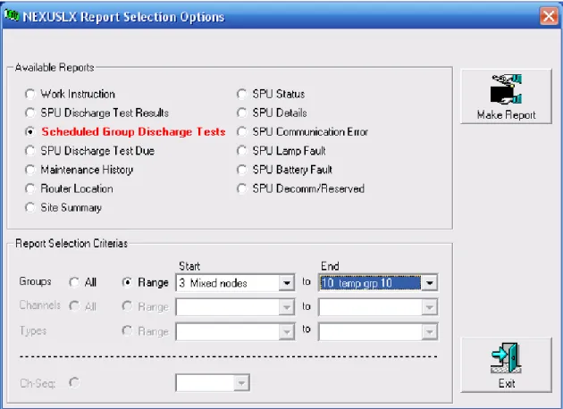
Figure 11: NEXUS LX Reports
NEXUS LX provides a variety of reports (see Figure 11). To make a report:
1 Click Reports menu item on the main form to open Report Selection Options form (Figure 11). 2 Select the required report from the Available Reports list.
3 Set Report Selection Criterias for the report. 4 Click Make Report button to generate the report.
5 To print the report, select the print button in the top left hand corner of the report. To export the report, select the button.
6 Click the icon in the upper right of the dialog box when you are finished.
3.6 Integrity Monitor
Nexus monitors the network periodically as background operation to check the integrity of the routers, repeaters, SPUs and data cable. When Nexus starts, Integrity Monitor is enabled and it polls the nodes at roughly 5 seconds interval. The current polling node is displayed on the bottom status bar.
Integrity Monitor operation can be turned off. To turn off Integrity Monitor, on the main form top menu System | Disable Integrity Check, Poll OFF will be displayed on the bottom status bar.
24 Nexus LX
3.7 Maintenance
Emergency Lighting testing and maintenance is a statutory requirement. The system must be tested every 6 months and the results must be recorded. Thereafter any faults must be rectified with the maintenance actions recorded in a log. The Work Instruction Report will provide a list of all fittings that require attention. Note that the suggested corrective actions in the report are a general guide as to the likely nature of the problems.
Maintenance Procedure:
1 Generate a Work Instruction Report
2 Identify the fittings requiring maintenance using the location data in the report - use the SPU’s node box Tool tab Yellow Blink function as an aid to locating the fittings.
3 Repair or replace the fittings as required.
4 Enter Maintenance Details. This is the logbook – it should always be kept up-to-date to ensure full compliance with AS/NZS 2293. See Figure 12.
5 Retest repaired/replaced fittings.
Figure 12: Node box Maintenance History
When you enter the details of maintenance performed you should then move the repaired fittings into the Retest Group, using Cut and Paste or Drag and Drop. Note that the icons for those fittings will also remain in the maintenance group until they have passed the appropriate tests. Schedule the Retest Group for testing.
Yellow Blink
This function causes the LED in any SPU to blink yellow as an aid to location.
Double click SPU icon to open its node box. On the Tools tab select Yellow Blink ON. To stop blinking, select Yellow Blink OFF.
Or
Double click the Maintenance Group icon. On the Tools tab, select Blink maint. Group. To stop the blinking select Stop Blinking.
Entering Maintenance Details
1 Open the SPU node box, on the Maint tab and press Enter Details. The Maintenance Details dialog box opens - in the Replaced section, check the boxes corresponding to any of the maintenance actions performed. Enter a Comment if required, and the name of the repairer in Carried Out By.
2 Press Save to save the details to the database then select OK.
View Maintenance Log Book
View the maintenance log book from the reports menu by selecting Maintenance History report.
Retest Repaired Fittings
To retest repaired fittings, select the Retest Group. Press on the toolbar. In the Program a Discharge Test dialog box set a time and date for the test. Press Confirm Test then select OK. The Discharge Test will be performed at the time specified. Any units that pass the test will be removed from the Retest Group and the Maintenance Group and will appear in their normal group.
3.8 Nexus Network Management
The sequence for commissioning a Nexus Network is set in Installation Guide and Commissioning Guide.
Commissioning the NUN
The NUN should be the first node commissioned ie before any of the routers are commissioned. If the NUN has not yet been commissioned, select Tools | Commissioning | NUN, click Commission then press the service request button on the NUN. Note that the NUN may also be commissioned from within the Network Utility Program (shown on page 31).
Commissioning Routers
1 Select the Channel Display tab.
2 Select Tools | Commissioning | Router/Channel. The Add Router dialog box displays.
26 Nexus LX 2 Select the Near Side and Far Side Router types – the default is 78kbps for standard data cable
channels.
3 Press Commission.
The dialog box displays "Press the Router Service Pin".
4 Go to the Router and press the Service Request button, located on the front of the Router. The dialog box will display a progress bar then "Successfully installed Router xx" when finished. Both SERVICE REQUEST LEDs on the Router will remain OFF when the Router is properly commissioned.
5 Repeat these steps until all Routers are registered into the Nexus database. 6 Press the icon in the upper right of the dialog box when finished.
Correcting Router Registration Mistakes
If you register a Router with the wrong Channel number, you can only correct this if either no nodes have yet been commissioned onto that channel, or you de-commission any nodes that have already been commissioned onto that channel. For this reason it is very important that the Routers are commissioned and verified correct before any nodes are commissioned.
To change the Channel number of a Router you must decommission it and then re-commission it with the correct channel number.
To decommission a Router, double-click the router’s icon, select the Tools tab, then De-commission Router. A dialog box is displayed, asking you to confirm - select Yes.
To re-commission a Router, double-click the router’s icon, select the Tools tab, then Re-commission Router. The Re-Commission Decommissioned Router dialog box displays – select Commission and then press the Router Service Pin.
Commissioning Repeaters
1 Select the Channel Display tab.
2 Select the Channel, which contains the Repeater by clicking on it in the Explorer. 3 If the repeater is in the trunk, double-click the Nexus Server icon and then select Install
Repeater. If the repeater is in a channel, double-click the channel’s router icon, then select the Tools tab, then select Install Repeater.
The Install Repeater dialog box opens:
4 Select the Near Side and Far Side Repeater types - the default is 78kbps for standard data cable channels.
5 Select Commission.
A message is displayed: "Press the Repeater Service Pin". 6 Go to the Repeater and press the Service Request button.
7 The dialog box displays a progress bar and "Successfully installed Repeater xx" when the process is complete.
8 Press the icon in the upper right of the dialog box when finished.
Changing Repeater Sequence
and after any repeaters previously commissioned. The channel display is not an exact representation of the physical channel, but it can be close. The Repeater icons can be moved (using drag and drop) to a position on the channel display that represents their real location. For instance, if on Channel 2, there is a repeater installed between nodes 2-35 and 2-36, then: click on the repeater icon, drag it and drop it on the icon for node 2-35. The Repeater icon will then be inserted between the two SPU icons. Repeaters on the trunk can be moved in the same way.
There is an alternative method for changing sequence. Double-click on the repeater icon and select Change Repeater Position. Choose the correct location from the pull down box.
Commissioning SPUs
SPUs must be commissioned in the correct channel sequence – otherwise they will be assigned an incorrect Channel Sequence number. Start at one end of the channel and work towards the other end.
Note that you can tell by looking at a SPU whether it has been commissioned. The LED of an
uncommissioned SPU will flash green. The LED of a commissioned SPU will be a static red. For more information about the LED colours that a SPU may display, see Nexus Error Messages (shown on page 52).
To commission SPUs:
1 Select the Channel Display tab.
2 Select the Channel that SPUs are going to be added to by clicking on the folder in the Channel Display list.
3 Select the button in the toolbar or select Tools | Commissioning | Emergency Light. The Add Device dialog box pops up - Next Unit to install displays the next available Channel Sequence Number.
4 Set Device Category for the type of device you want to install. The default is Emergency Light 5 Press Commission - the dialog box displays a prompt instructing you to press the button on the
SPU. Go to the selected SPU. The LED of an uncommissioned SPU will be a flashing Green colour. Push the test button, then release it. At the end of the commissioning process – after about 10 seconds - the LED should change to static red. The dialog box displays a progress bar and, when the SPU is registered, "Successfully installed SPU x-x".
6 It is critical to keep SPU Channel Sequence Numbers in order. If there are SPUs that have not yet been installed, or if you know that there will be SPUs installed in the future, you can reserve Channel Sequence Numbers for them. In this case select Reserve. The icon will be put in place of the SPU icon.
7 Next Unit to install will increment. Repeat the process until all SPUs have been installed for that
Channel.
8 Click the icon in the upper right of the dialog box. You can return and add further SPUs to a Channel at any time.
Note: Error Messages. Most errors encountered during node registration are caused by poor communications due to faulty data cabling.
Communications faults must be located and fixed before the node(s) can be commissioned.
28 Nexus LX
Decommissioning and Recommissioning SPUs
When you decommission a node, the decommissioned symbol is displayed in the Channel Display. Decommissioned nodes can be recommissioned later.
To decommission an SPU, double-click its icon, select the Tools tab, then De-commission SPU. A dialog box is displayed, asking you to confirm - select Yes.
To recommission a node, double-click on the icon. The Re-Commission SPU dialog box will pop up. Select Commission, then press the test button on the SPU.
Inserting Extra SPUs
Even if nodes have already been allocated Channel Sequence Numbers, you can add extra nodes between them.
To add extra nodes (for example between nodes 4-5 and 4-6) right-click on SPU 4-5 and select Insert Device. The Device to Commission box pops up. Select the type of device to insert – in this case it is an Emergency Light. The Add Device dialog box pops up. The first node is numbered 4-5.01 and you can add nodes up to 4-5.99. Commission the node in the usual way. You can decommission,
recommission and reserve an inserted node as you would any other node.
Edit Location Details for Routers, Repeaters and SPUs
To edit the location details for an SPU, double-click the SPU icon to open node box. Select the Details tab, and then Edit Location Details button. A table lists all location details of this channel SPUs is displayed. Enter the appropriate information. It is possible to move directly to the next SPU in sequence from this window and to copy data from the previous SPU.
For Routers, double-click the Router icon and select the Tools tab. Select Enter/Edit Location Details, A table lists all location details of all routers and repeaters is displayed. Enter the appropriate information.
For Repeaters, double-click the Repeater icon and select Edit Location. A table lists all location details of all routers and repeaters is displayed. Enter the appropriate information.
Packet Counting
Packet Counting is a process that is used to test data communications quality.
To perform a packet count for all the Routers on the Trunk, double-click on the Nexus Server icon, select the Communications tab, then select Start. The result (Pass or Fail) will be displayed in the box.
You can also individually packet count routers from the Router dialog box. Double-click on the Router icon, select the Comms Test tab and then under Perform Router Packet Count select Start. The result (PC %) will be displayed in that box.
To packet count all SPUs in a channel, double-click on the Router icon for that channel, select the Comms Test tab and then under Perform Channel Packet Count select Start. The result (Pass or Fail) will be displayed in the box.
To packet count individual SPU, double-click on the SPU icon, select Tools tab and then under Perform Immediate Packet Count select Start. The result (Pass or Fail) will be displayed in the
box.
It is possible to display the packet count % result for each device underneath that device in the
Channel Display. This is an alternative to displaying the Channel Sequence number or Router number.
For the trunk press the button or the button to toggle between displaying the Router Number and the Packet Count.
For a channel press the button or the button to toggle between displaying the Channel Sequence Number and the Packet Count.
3.9 Nexus Database
The Nexus database is a set of database files that stores the details of all the SPUs, routers and repeaters on the network. When the Nexus program is started for the first time on a PC, a blank database is created. As routers, repeaters and SPUs are commissioned, they are added to this database. The database can be backed up, deleted and restored from backup as required.
Backing Up the Database
It is necessary to back up the database information to prevent loss of data.
Stanilite recommends that you backup the database regularly onto external (removable) backup media.
Backups should be performed at least:
After each major maintenance (i.e. after testing and repairs have been completed every 6 months).
Whenever new fittings are added or old ones removed. Whenever fitting descriptions are changed.
To create a backup
1 Select Tools | Database | Save. A confirmation box will pop up – select Yes. Nexus 2000 will shut down automatically and the Save Database Utility window will open
2 Select either Save database or Zip Save database. The Zip Save database option will backup the database in a compressed format.
3 Select Choose Location. The Browse For Folder dialog box will open 4 Select an existing folder or create a new folder then select OK. 5 Select Save Database. A confirmation box will pop up – select Yes.
6 A dialogue box opens that says 'The saving of the database was successful. Do you wish to start Nexus LX?'
7 If you want to start Nexus, select Yes.
8 Copy the saved database to external media and keep in a secure location away from the computer.
Retrieving databases
Loading a backed-up database back into Nexus is a specialist task. It should only be necessary when the Nexus Server has been lost or destroyed. In this circumstance contact Stanilite for advice.
4.
Network Utility User Guide
In This Chapter
Network Utility Program... 31 Commissioning the NUN ... 31 Discovering Nodes ... 32 Getting Info from Nodes in the Table ... 32 Sorting, Saving and Retrieving Node Tables ... 32 Setting Routers and Repeaters Online/Offline ... 33 Packet Counting Nodes ... 33 Identifying Nodes... 34 Discovering Hidden Nodes ... 34 Shutting Down the NUP... 35
4.1 Network Utility Program
The Network Utility Program (NUP) is used in conjunction with the Network Utility Node (NUN) to test the data communications of a Nexus network
4.2 Commissioning the NUN
The NUP shares the Nexus database. It can be run at the same time as Nexus LX. Whichever program is run first on a new server will create a blank Nexus database.
The NUN should be the first node commissioned ie before any of the routers are commissioned.
In the NUP:
Select Start | Programs | NEXUS LX | Network Utility
Choose the network interface – usually LON1. The NUP will start and if the NUN has not been commissioned yet, will prompt to press the service request button on the NUN. In this case press this button to commission the NUN.
32 Nexus LX (Note that the NUN may also be commissioned from within Nexus (see "Step 3: Commission the NUN" shown on page 45).
Figure 8: Network Utility Program Window
4.3 Discovering Nodes
The NUN is able to discover nodes connected to the network. It does this by sending out multiple requests for all nodes to transmit back in response. Select Action | Discover devices or click the button. The NUP will then discover all devices that it can communicate with. Routers will generally be discovered before SPUs because they are programmed to respond with a higher priority. The discovery process can take a long time to finish because it attempts to communicate with nodes that may be communicating very poorly. It is not necessary to let this process run until it stops itself. Use the button to terminate the process when enough nodes have been discovered.
Once a node has been discovered, the NUP displays its Neuron_ID, Program_ID and Type on one row in the main display table.
4.4 Getting Info from Nodes in the Table
If nodes have been commissioned previously, there may be additional useful information stored in them. To display this information, first select the desired nodes by clicking on each row then click the
button. To select all nodes in the list, click the button. To de-select a row, click on it again or click the button again.
4.5 Sorting, Saving and Retrieving Node Tables
Delete Rows
To delete a row, highlight it by clicking on that row then either use the Delete button on the keyboard or the button. To delete multiple rows highlight using the ctrl or shift buttons on the keyboard together with the mouse, then the button.
Sort Rows
label (eg Type, PC% etc). Click the label again to sort the table in reverse order. This can be useful for displaying nodes in order of increasing or decreasing packet count or for displaying nodes in order of channel sequence – although this last one can only be done after a site has been commissioned.
Copy and Paste Table
The list of Neuron IDs for each channel can be very useful for diagnosing communications problems. The contents of the currently displayed table can be saved to a file and pasted back in from a file. It can also be pasted into a program such as Microsoft Excel if required.
To copy a table into the Windows clipboard, first delete any unwanted rows and then click the button. Open a document in another application (such as Excel, Notepad etc) and paste using that program's menu.
To copy a table directly to a text file in tab-delimited format, select Save | Tab Delimited from the menu. A new form will be displayed prompting for a file name and location. Choose a filename and location and Save.
To paste the contents of a file back into the table, open the text file (using say Windows Notepad) and copy the contents to the Windows clipboard (ie select data then Edit | Copy). Go back to the NUP and either select Edit | Paste or click . This will append the data to whatever rows are displayed in the table.
Using this method, it would be possible to store the Packet Count results for each channel on the site either in one file or in individual files.
4.6 Setting Routers and Repeaters Online/Offline
Routers and repeaters can be online or offline. When they are online, they transfer packets as required. When they are offline they will not transfer packets. This property is useful when you are only interested in nodes on one particular channel. If you set all the routers on the trunk offline except for the one on the channel you are interested in then the discovery process will only discover nodes on that channel. To set a router offline, it must be in the list of discovered nodes. Select the router from the list by clicking in the checkbox on the left in the Neuron ID column then click the button. If the discovery process is run again, that router will prevent nodes on that channel responding. You must turn all the routers and repeaters back online before you attempt to use Nexus again otherwise those channels will not communicate. To do this, select them and click the button.
4.7 Packet Counting Nodes
The NUN uses a packet counting process (see "Data Test Mechanism – Packet Counting" shown on page 41) to test the quality of the communications with a node. Once a node has been discovered and is in the main list, it can be packet counted. To do this, select the desired nodes individually or select them all by using the button. Click the button to start the packet count process. This process may take some time depending on how many nodes were selected and how good the communications are on that channel. As each node is tested, a Packet Count result will be displayed.
There are 3 parameters that can be set for packet counting. They are displayed on the right hand end of the toolbar.
34 Nexus LX The first is the transaction timer. The default value is 48 milliseconds. This value is OK for most circumstances, although when nodes are situated behind a number of repeaters in series it may be necessary to increase this value.
The second is the number of packets. The default is 100 packets. This value may be reduced to give a faster though less accurate result.
The third is the wink interval. The default is 500 milliseconds – this will result in an LED blink rate of 1 per second.
4.8 Identifying Nodes
It will often be necessary to physically identify nodes listed in the NUP table. In particular you may want to identify which nodes are communicating on a channel so that you can determine which are not. There are two methods available:
Winking Nodes
The Wink by Neuron ID function blinks the red LED on a single highlighted SPU at a rate of approx once per second. To do this, highlight the desired node and select Action | WinkbyNeuronID or click
. The Wink all function sends out a broadcast wink command which causes every node to wink. Note that any nodes on channels behind routers or repeaters that have been put offline will not wink. To do this select Action | Wink all or click .
To stop the wink select Action | Stop or click .
Comments Column
The comments column is used to record any comments about nodes. To add a comment, double click over the comments cell for a particular row.
Receiving Service Pin Messages
When the SPM checkbox in the main toolbar is ticked, the NUP will respond when the test button of a node that is listed in the table is pushed. A box will pop up displaying the Neuron_ID of the node. When you acknowledge this box by clicking the OK button, the row for that node will be highlighted. This is the main method whereby nodes in the table can be physically identified. It is most useful when nodes have not yet been commissioned and there is not yet any information available to distinguish one node on a channel from another.
4.9 Discovering Hidden Nodes
Once a node has been commissioned, it has an address stored within it. That address is made up of a number of parts, one of which is its channel. If you disconnect a commissioned node from one channel and connect it to another, and then attempt to discover all the nodes on that second channel, this node will not be discovered. The reason for this is that the router on that second channel will not transfer the responses from that node back to the trunk because it thinks they are coming from the wrong channel. In order to discover nodes that may have inadvertently been swapped around, it is necessary to temporarily change the router so that it acts as a repeater. In this case a repeater will transfer the response from the node because a repeater is not selective in what it transfers.
This function is one of a set of functions for advanced users of the system.
To turn a router into a repeater, right click the mouse on the desired row and select Make repeater. After you have finished discovering that channel, restore the router to its normal mode by selecting Make router in the same fashion.
4.10 Shutting Down the NUN
Shut down the program either by using Action | Exit or by clicking the icon in the upper right of the dialog box. This will pop up a reminder to turn any temporary repeaters back into routers and to turn them back online. You will have to respond yes to this in order to shut down. This will not carry out those actions for you – it is simply a reminder to do so.
5.
Installation Guide
There is a product specific installation sheet packed with every Nexus product. That document sets out in detail the procedure for mounting the product and connecting it to the data network and the mains supply.
In This Chapter
Data Cable Connection... 37 Data Communications ... 40 Testing Data Communications ... 43 Preparation for Commissioning ... 46 Installation List... 47
5.1 Data Cable Connection
Stanilite (or its agents) will not commission incorrectly wired installations.
Data Cabling Rules
It is the installer’s responsibility to ensure compliance with relevant standards for installation of cabling. Data cable must be installed by a registered Cabling Provider in accordance with the requirements of AS/ACIF S009 if the Nexus Server will be connected to the PSTN. Additional information is available in this guide (see "Nexus System Design Sequence" shown on page 5).
Data cable connection
The standard Stanilite Nexus data cable is a single twisted data pair plus shield. The two data wires are blue and white respectively. Nodes are connected in parallel across the data pair – refer to the figure in
SPU Data connection (shown on page 37). The data pair is unpolarised.
The shield consists of a foil wrap with a copper drain wire. The shield is connected so as to maintain continuity across all the joins along the entire length of a channel segment. The shield must remain electrically isolated from the data pair and any other metalwork or potential earthing point throughout the length of the channel segment, except for the one point where it must be connected to earth. Earthing points are provided for this purpose at Routers and Repeaters.
SPU Data Connection
SPU nodes have either a 2 terminal or 3 terminal connection for the data cable. When there are 2 terminals, they are for the data pair. When there are 3 terminals, the two outer terminals are for the data pair and the central terminal is for the shield. This central terminal is floating – specifically it is not connected to earth. It is provided for the convenience of joining the drain wires. In a 2 terminal SPU connection, the shields are twisted together and folded back along the data cable and insulated. In
C
H A P T E R5
38 Nexus LX a 3 terminal SPU connection, the shields are joined in the centre terminal.
Figure 9: Data cable connection for 2 and 3 terminal SPU connection
Figure 10: Data cable connection for 2 and 3 terminal SPU connection – cable end
Router and Repeater Data Connection
A router is a device that selectively transfers data packets between the trunk and a channel. It consists of 2 nodes, A and B, internally connected back to back. By convention node A is connected to the channel and node B is connected to the trunk.
A repeater is a device that transfers all data packets between one channel segment and another channel segment. Routers and repeaters are physically identical but have a different software configuration. The following figure shows the router connections required for the most common network
configuration. Note that the terminators for each node in the router are only switched on when that router node (A or B) is at the end of a channel segment.
Routers and repeaters always have a 3 terminal data connection. The centre pin in the data cable terminal block for routers and repeaters is earthed. As with any other channel segment, the Trunk cable shield must only be connected to earth at one point. Refer to the following figure, which shows an example of how shield earthing should be done on the trunk. The shield earthing arrangement must be recorded on the as-built plans.
Figure 11: Typical router data cable connection
Data Cable Preparation for 2 terminal connection
This is the procedure for preparing the data cable for a 2 terminal data connection in the middle of a channel segment or a 3 terminal router or repeater connection when the shield is connected to earth at another location:
Strip back and remove the outer yellow sheath of both cables for approximately 30mm from the end being careful not to damage the conductor insulation under the shield. Peel back the shield to the level of the outer sheath and unravel to allow it to hang away from the cable to expose the inner insulated conductors. Remove the foil shield leaving the shield drain wire. Strip the data wires as shown.
40 Nexus LX Holding the cables side by side, twist the drain wires of the two cables together. This will provide for continuity of the shields. Twist the data wires into like coloured pairs and fold the drain wires back as shown.
Bind with tape, ensuring that the shield is fully insulated, then insert the prepared cable into the terminal block and secure with a cable tie. Note that some products have a fixed terminal block for data cable connection.
Data Cable Preparation for 3 terminal connection
This is the procedure for preparing the data cable for a 3 terminal data connection or a 3 terminal router or repeater connection when the shield is connected to earth:
Prepare the cable ends as shown.
Holding the cables side by side, twist the drain wires of the two cables together and twist the data wires into like coloured pairs.
Insert the prepared cable into the terminal block and secure with a cable tie. Note that some products have a fixed terminal block for data cable connection.
5.2 Data Communications
This section describes the format of Nexus data, it's transmission, testing and diagnosis of faults.
Data Packets
The Nexus system communicates using a packet switching network. Data is contained within a discrete structure known as a packet. The data packet is a series of voltage transitions on the data cable within a channel segment. A transaction between nodes generally consists of a number of packets sent back and forth the between the nodes. If one or more of the packets is damaged, the transaction will fail and the Nexus system will report an error. By far the most common cause of damage to data packets is faulty data cable installation.
Transmission Line
Connections made to a transmission line must meet certain criteria if the data transactions are to succeed. If the cabling limits and structure defined by the channel segment are satisfied then the criteria for a transmission line will also be satisfied.
Consequences of Faulty Data Cable Installation
A correctly installed channel segment is effectively a single length of data cable with a terminator at each end and with nodes connected in parallel along its length. The cabling limits for a channel segment using standard Nexus data cable are 50 nodes over 1000 metres of cable. The shield is continuous along its length and is earthed at one point.
If the cable is too long, a signal sent from one end of the cable will be attenuated (ie reduced in
amplitude) by the cable resistance as it travels along the cable to the point where the signal amplitude will be too low for reception by a node at the far end of the cable.
If too many nodes are connected along the length of the cable, the loading imposed by each of the
nodes will attenuate a signal sent from one end of the cable. The result will be the same as if the cable were too long.
If one or both of the terminators are left off then communications on that channel will be
disrupted. This is because without the terminators, the unterminated ends of the data cable reflect signals generated by nodes on the segment. These reflected signals interact with the signals themselves, resulting in distortion or even cancellation of the original signal. This may prevent the intended recipient nodes from correctly receiving the signal.
If the data cable is broken at one point, the remaining section of data cable will be unterminated
and communications will be disrupted in the same way.
If just one conductor of the data pair is broken, signal current may still flow via the stray coupling capacitance to the shield so that units beyond this break may still communicate to some extent - although communication will be severely disrupted.
If additional terminators are connected to a channel segment, the impedance of the cable circuit
will be lowered in the vicinity of the extra terminators. This will result in excessive attenuation of the signal.
If a T junction is used within a channel segment, that segment will effectively have 3 ends rather
than 2. In this case signals generated by a node on this segment will reflect off the transmission line discontinuity caused by the T junction resulting in the same kind of distortion caused by lack of terminators.
If two dissimilar types of data cable are used within a channel segment, the junction between the
cables is a transmission line discontinuity. This will cause reflections and consequently, signal distortion.
If the shield is not connected to earth and is left to float, then the capacitive coupling of external noise sources to the data pair is increased, and the potential for signal distortion is increased. When the shield is earthed, the capacitive coupling is reduced and the cable is effectively shielded from external electric field disturbance.
Data Test Mechanism – Packet Counting
The basic data test mechanism in Nexus is packet counting. This is one of the principal functions of the NUN. Packet counting involves sending out a string of data packets to a specific node requesting a response. If 100 requests are sent out and 100 responses are received back, the packet count for that node is 100%. If there is a fault in the data cable installation for that channel segment, the packet count may be less than 100% depending on the type of fault and where that particular node is located on the segment. If every node on a segment returns a packet cont of 100%, then that segment has no faults.
42 Nexus LX
two numbers (see "Number the Channels and Apply Channel Sequences" shown on page 7) the
Channel Sequence Number and the SPU_ID. These numbers are only associated with the node after it has been registered onto the system. Prior to that , the node can be referred to by its Neuron_ID. This is a unique 48 bit number built into each Neuron microcontroller at the time of manufacture. The NUN uses a process of discovery to determine the identity of nodes so that they can then be packet counted.
Diagnosis of communication faults
Communication problems are nearly always caused by incorrect wiring of the data cable.
Symptoms
Some nodes not discovered, some communicate perfectly but others communicate poorly Most or all nodes discovered, some communicate perfectly but others communicate poorly Possible causes:
One or both terminators not connected
Broken or cut data cable – either one or both conductors
Wrong wiring topology (e.g. a "T" or star connection made at a node)
Intermittent connections due to broken conductors or loose or over-tightened terminal screws
More than two terminators connected to a channel segment
Too many nodes on a channel segment
Channel segment too long
Incorrect connection of cable shields Wrong Data Cable type
The nearness of the data cable to electromagnetic noise sources
Remedial Actions:
Check each end of the channel segment to see if the terminators are connected.
Identify which nodes have been discovered and which are suspect.
Check the Service Pin Message (SPM) box (near the top of the window).
Press the test buttons on all the units on the channel, working from the router out along the
channel.
If a service pin message is received from a fitting with a Neuron_ID that is not in the list it will be added and highlighted.
Query and packet count any fittings found in this way.
Check the data cable connection at the last good node then at each suspect node
In most cases the cause of the problem will be found where one or more of the nodes connects to the channel. It is less common to find a problem in the data cable between nodes – although it is possible the cable is cut as a result of construction or refurbishment processes.
Symptoms