OPERATION MANUAL
PORTABLE, SELF-CONTAINED VENTILATION SYSTEM
(VENTILATOR, COMPRESSOR, AIR/OXYGEN MIXER)
UNI-VENT
®
Eagle
™
700 SERIES
MODEL 754
Impact Instrumentation, Inc.
27 Fairfield Place
West Caldwell, New Jersey 07006
© 1997 Impact Instrumentation, Inc. REV. 1.85L (03/11)
T A B L E O F C O N T E N T S
_____________________________________________________________________________________________
______________SUBJECT PAGE________
LIST OF ILLUSTRATIONS iv
CONVENTIONS, TERMINOLOGY, DEFINITIONS AND
ABBREVIATIONS AS USED IN THIS MANUAL vi
A WORD ABOUT EAGLES vii
SHIPPING CONTENTS vii
ACCESSORIES LIST vii
CALIBRATION/PREVENTATIVE MAINTENANCE NOTICE viii
UNPACKING viii
LOCATION OF USE viii
WARNINGS AND CAUTIONS REGARDING USE viii
ASSEMBLY, INTERCONNECTIONS AND INITIAL ADJUSTMENTS ix
SECTION I. OPERATION 1-1
INTRODUCTION 1-1
FEATURES 1-1
DESCRIPTION OF CONTROLS, VISUAL INDICATORS AND CONNECTIONS 1-2
CONTROLS 1-2
EXTERNAL AIR OFF/ON Switch - SIGH OFF/ON Switch - PEEP OFF/ON-set Switch - PRESSURE PLATEAU OFF/ON Switch - HIGH PRESSURE ALARM/PEAK INSPIRATORY PRESSURE RELIEF Control - LOW PRESSURE ALARM Control - VENTILATION RATE Control - INSPIRATION TIME/I:E RATIO Control - TIDAL VOLUME Control - AIR/OXYGEN MIXER Control - ALARM MUTE/CANCEL Switch - MANUAL BREATH/TRIGGER Switch - MODE SELECTOR Switch - LCD VISUAL INDICATORS
STATUS 1-6
MODE - Vmin - INSPIRATION/EXHALATION - POWER INFORMATION CENTER - PEAK AIRWAY PRESSURE - MEAN AIRWAY PRESSURE - DIGITAL BAR GRAPH - HIGH and LOW AIRWAY PRESSURE ALARM SETPOINTS - Paw - EXTERNAL AIR - SIGH - PEEP - PRESSURE
PLATEAU - HIGH AIRWAY PRESSURE ALARM (setpoint) - LOW AIRWAY PRESSURE ALARM (setpoint) - RATE - INSPIRATION TIME/I:E RATIO - TIDAL VOLUME - FIO2
T A B L E O F C O N T E N T S, (cont'd)
_____________________________________________________________________________________________
______________SUBJECT PAGE________
LED VISUAL INDICATORS
STATUS 1-7 CHARGE 1-8 ALARM ALARM 1-8 SYSTEM FAILURE 1-8, 1-9 LCD VISUAL INDICATORS ALARMS - OPERATING 1-8
BATTERY LOW - EXTERNAL POWER LOW - LOW PRESSURE - DISCONNECT - HIGH PRESSURE - APNEA - HIGH PEEP - O2 LOW/FAIL - EXT AIR LOW/FAIL - FIO2 - PRESSURE ALARM SETTINGS - VT - COMPRESSOR
ALARMS - NON-OPERATING 1-9
INVERSE I:E - TRANSDUCER CALIBRATION ABORT - SYSTEM FAILURE - VENTILATOR FAILURE
ALARMS - ADVISORY 1-10
INSPIRATION TIME TRUNCATED TO 3-SEC - PLATEAU VOLUME - VT SETTINGS - PREVENTATIVE MAINTENANCE -
EXTENDED NON-USE/STORAGE - EXTERNAL POWER FAILURE - TOTAL FLOW BACKUP
CONNECTIONS 1-10
OXYGEN INLET - AIR INLET - GAS OUTLET - TRANSDUCER - EXHALATION VALVE - EXTERNAL POWER JACK -
COMMUNICATIONS PORT
OPERATING POWER SELECTION & STOPPING 2-1
INITIAL SET-UP, SELF-CHECK AND TRANSDUCER CALIBRATION 3-1
INITIAL SET-UP 3-1
SELF-CHECK 3-3
TRANSDUCER CALIBRATION 3-3
AUTOMATIC CALIBRATION (AUTO CAL) MANUAL CALIBRATION
USER PROGRAMS 3-4
T A B L E O F C O N T E N T S, (cont'd)
_____________________________________________________________________________________________
______________SUBJECT PAGE________
MODES OF OPERATION 4-1
ASSIST-CONTROL VENTILATION (ACV) 4-2
SYNCHRONIZED INTERMITTENT MANDATORY VENTILATION (SIMV) 4-3
CONTINUOUS POSITIVE PRESSURE VENTILATION (CPAP) 4-5
CONTROL VENTILATION DURING APNEA 4-5
USING POSITIVE END EXPIRATORY PRESSURE (PEEP) 4-6
USING PRESSURE PLATEAU 4-6
BACKUP VENTILATOR 4-7
HUMIDIFIERS AND HEAT MOISTURE EXCHANGERS (HME'S) 4-7
OPERATOR PERFORMANCE CHECKS 4-7
ALARM FUNCTIONS 5-1
OPERATING ALARMS 5-1
BATTERY LOW - EXTERNAL POWER LOW -
LOW PRESSURE - DISCONNECT - HIGH PRESSURE - APNEA - HIGH PEEP - O2 LOW/FAIL - EXT AIR LOW/FAIL - FIO2 - PRESSURE
ALARM SETTINGS - VT - COMPRESSOR
NON-OPERATING ALARMS 5-4
INVERSE I:E - TRANSDUCER CALIBRATION ABORT - SYSTEM FAILURE - VENTILATOR FAIL
ADVISORY ALARMS 5-6
INSPIRATION TIME TRUNCATED TO 3-SEC - PLATEAU VOLUME - VT SETTINGS - PREVENTATIVE MAINTENANCE -
EXTENDED NON-USE/STORAGE - EXTERNAL POWER FAILURE - TOTAL FLOW BACK UP
T A B L E O F C O N T E N T S, (cont'd)
_____________________________________________________________________________________________
______________SUBJECT PAGE________
ROUTINE CARE: CALIBRATION, CLEANING AND
PREVENTATIVE MAINTENANCE 6-1
CALIBRATION 6-1
CLEANING 6-1
PRESSURE HOSE 6-1
COMPRESSOR INLET FILTER 6-1
PREVENTATIVE MAINTENANCE 6-1
BATTERY CARE AND RECHARGING 7-1
IN CASE OF DIFFICULTY 8-1
OPERATOR CORRECTABLE PROBLEMS 8-1
OPERATOR PROBLEMS REQUIRING SERVICE 8-1
STORAGE INFORMATION 9-1
SPECIFICATIONS 10-1
LIMITED WARRANTY 11-1
LIST OF ILLUSTRATIONS
_____________________________________________________________________________________________
________FIGURE DESCRIPTION PAGE________
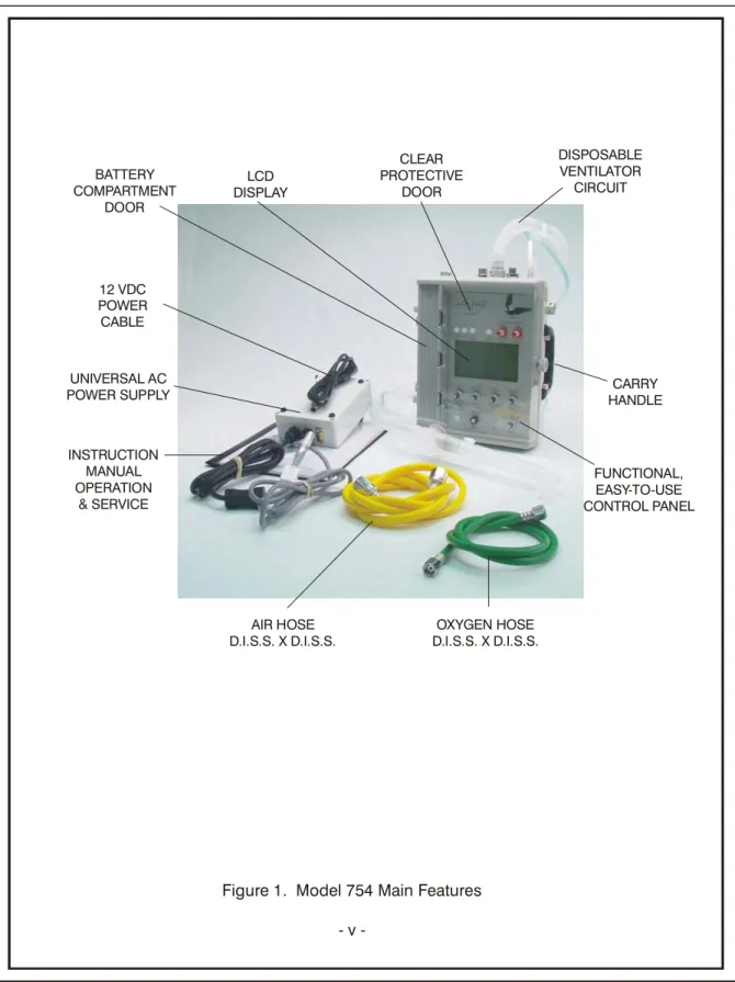
1 Model 754 Main Features v
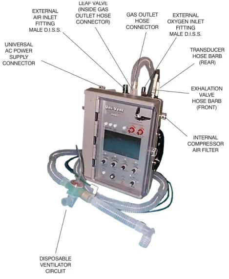
2 Interconnection Diagram x
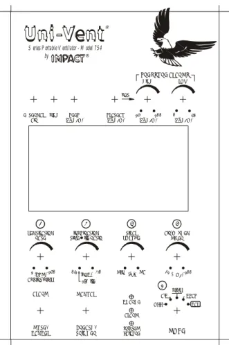
3 Control Panel 1 - 2
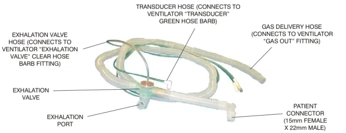
4 Disposable Ventilator Circuit 1 - 11
5a Initial Setup 3 - 1
5b Initial Setup 3 - 2
Figure 1. Model 754 Main Features 12 VDC POWER CABLE UNIVERSAL AC POWER SUPPLY OXYGEN HOSE D.I.S.S. X D.I.S.S. INSTRUCTION MANUAL OPERATION & SERVICE CARRY HANDLE CLEAR PROTECTIVE DOOR DISPOSABLE VENTILATOR CIRCUIT LCD DISPLAY BATTERY COMPARTMENT DOOR FUNCTIONAL, EASY-TO-USE CONTROL PANEL AIR HOSE D.I.S.S. X D.I.S.S.
CONVENTIONS, TERMINOLOGY, DEFINITIONS AND
ABBREVIATIONS AS USED IN THIS MANUAL
CONVENTIONS WARNING
A WARNING message identifies conditions that could have an adverse effect upon the patient or operator.
CAUTION
A CAUTION statement identifies conditions that could damage this device.
NOTE
Information immediately following is of sufficient importance that emphasis is made.
TERMINOLOGY
Air/Oxygen Mixer - Blender, Gas Blender Model 754 - Uni-Vent®
Pressure Plateau - Plateau
Uni-Vent® - Model 754, Ventilator, Eagle™
Ventilator-Compressor-Air/Oxygen Mixer - Ventilator DEFINITIONS
Gas - Air or oxygen or the resultant mixture of these two gases
Ventilator - Any reference to the Model 754, Uni-Vent®, Ventilator-Compressor-Air/Oxygen Mixer # - Denotes that display will indicate some number between 0 an 9 for each appearance of "#" ABBREVIATIONS
Airway Pressure - Paw
Alarm Message Center - AMC Assist-Control - A/C
Assist-Control Ventilation(s) - ACV Breaths Per Minute - BPM
Centimeters of Water - cmH2O
Continuous Positive Airway Pressure - CPAP delivered - del
End Tidal Carbon Dioxide - ETCO2 Fraction of Inspired Oxygen - FIO2 Light Emitting Diode - LED Liquid Crystal Display - LCD liters - L
Liters Per Minute - LPM milliliters - ml
Oxygen - O2
Peak Inspiratory Pressure - PIP
Positive End Expiratory Pressure - PEEP Pounds Per Square Inch - PSI
Power Information Center - PIC
Synchronized Intermittent Mandatory Ventilation(s) - SIMV Tidal Volume - VT
A WORD ABOUT EAGLES
This very special Uni-Vent® was named Eagle™, to represent its leadership role in the world of portable ventilators. Where the eagle has come to symbolize power - this Eagle™ represents the most powerful, self-contained portable ventilator available today. Where the eagle is known for its skills - this Eagle™ possesses skills never before found in a portable ventilator this small. And where the eagle is known for its keen sight - this Eagle™ sees a future that no other portable ventilator has ever seen. The Uni-Vent® Eagle™ - its not just another bird!
SHIPPING CONTENTS
Each Uni-Vent® Eagle™ Model 754 is shipped with the following components: 1 ea. Ventilator, Compressor, Air/Oxygen Mixer
1 ea. Ventilator Circuit, Disposable, Single Patient Use
1 ea. High Pressure Hose, D.I.S.S. Oxygen X D.I.S.S. Oxygen, 6' Long 1 ea. High Pressure Hose, D.I.S.S. Air X D.I.S.S. Air, 6' Long
1 ea. Universal AC Power Supply (standard) 1 ea. 12 VDC Power Cable
1 ea. Operator's Manual, Model 754 1 ea. CD, Manual
ACCESSORIES LIST
The Accessories List contains common items, required from time to time. Each item is preceded by its part number. Accessories may be ordered direct from Impact®. When ordering, please include the part number, description and quantity required.
Send written purchase orders to: Impact Instrumentation, Inc. Telephonic orders: 973/882-1212
P.O. Box 508 Fax orders: 973/882-4993
West Caldwell, New Jersey 07007-0508
PART NUMBER DESCRIPTION
334-0020-00 Strap, Velcro®, 24" Long
402-0014-00 Case, Padded, Ventilator & Accessories 402-0016-00 Case, Padded, Ventilator
820-0053-00 Heat/Moisture Exchanger, Single Patient Use 820-0067-15 Ventilator Circuit, Disposable, Single Patient Use (Case/15)
820-0096-15 1-Way Valve (Antiasphyxia) (Case/15) 820-0097-15 Oxygen Reservoir (Case/15)
825-0002-00 High Pressure Hose, D.I.S.S. Oxygen X D.I.S.S. Oxygen, 6' Long 825-0004-00 High Pressure Hose, D.I.S.S. Air X D.I.S.S. Air, 6' Long
703-0754-08 Universal AC Power Supply 703-0754-03 12 VDC Power Cable
CALIBRATION/PREVENTATIVE MAINTENANCE NOTICE
This device should be incorporated into a regular preventative maintenance program to insure compliance with operating specifications (see LIMITED WARRANTY statement). Calibration measurements should be made each year unless significant usage warrants a shorter period between preventative maintenance inspections. A complete calibration check should be made following each 2000 hours of cumulative use or 12-month period. A pressure-sensitive Calibration label is attached to the outer case, indicating when the last calibration was performed and the next calibration is due. DO NOT remove this label. Following 6-months of continuous storage/non-use, this device should be examined, operationally tested, and its batteries recharged before patient-use is attempted. The Model 754 contains internal clocks that monitor cumulative use and storage/non-use periods. Appropriate Advisory Alarm messages will appear in the Alarm Message Center when calibration/preventative maintenance is required.
UNPACKING
Compare shipping case contents against SHIPPING CONTENTS list. Examine instrument for any obvious signs of shipping damage. If there is no apparent sign of mechanical damage, read instructions contained within this Manual before attempting operation.
LOCATION OF USE
The Uni-Vent® Eagle™, Model 754, is a transportable device, therefore, its location of use will vary. When operated in a wet environment, users should take precautions and protect this device by covering it with a protective barrier (small tarp, plastic sheet, etc.).
CAUTION: Routine use of an external filter (Impact p/n 465-0024-00 or equivalent) will prevent entrainment of particulate and increase the service life of the flow transducers.
WARNINGS AND CAUTIONS REGARDING USE
WARNING: Electric shock hazard, do not remove equipment covers.WARNING: Do not operate this instrument prior to reading instructions contained within this Manual. WARNING/CAUTION: Possible explosion hazard if used in the presence of flammable anesthetics.
WARNING/CAUTION: DO NOT block or connect the ventilator circuit hose to the Internal Compressor Air Filter port (see Figure 2).
CAUTION: Federal law restricts this device to sale by or on the order of a physician. WARNINGS AND CAUTIONS REGARDING USE, (cont'd)
CAUTION: Service is to be performed by qualified biomedical equipment technicians only.
CAUTION: Do not allow oil and grease to enter system. See ROUTINE CARE AND MAINTENANCE section entitled CLEANING for additional instructions.
ASSEMBLY, INTERCONNECTIONS AND INITIAL ADJUSTMENTS
ASSEMBLY:Model 754 - No assembly is required before placing this device into operation.
INTERCONNECTIONS:
CAUTION: Follow interconnection instructions prior to placing this device into service (see Figure 2).
1. For use with external oxygen: connect high pressure oxygen hose between OXYGEN inlet port and a 50-PSI external oxygen source. Use only medical-grade oxygen (see Figures 5a and 5b).
2. For use with external air: connect high pressure air hose between AIR inlet port and a 50-PSI external air source. Use only medical-grade compressed air (see Figures 5a and 5b).
3. Connect disposable ventilator circuit to its respective gas outlet, transducer, and exhalation valve connectors on Model 754 Connector Panel. Observe directions included with disposable ventilator circuit (see Figure 4).
The gas outlet contains a leaf valve mounted flush to its inside – it has two purposes. First, should a spontaneously breathing patient require supplemental flow or the ventilator is not triggering in response to the patient’s breathing effort, the leaf valve opens allowing entrainment of ambient air (acting as an antiasphyxia valve). Second, should the gas outlet port or the ventilator circuit become blocked, the leaf valve wedges itself into the large holes it normally blocks (acting as a protective blow-out valve) to protect the patient and ventilator from excessively high pressures. Never block (or occlude) the gas outlet port or connected ventilator circuit when the ventilator is operating. Prior to operation, verify that the leaf valve is properly seated otherwise re-seat before patient use.
Location of Leaf Valve inside Adapter Leaf Valve in position
Should valve dislodge, use blunt end of a small diameter object to gently push wedged section(s) of leaf valve inward so it dislodges from peripheral hole(s) and re-seats itself against inner wall of gas outlet connector. Visually verify leaf valve lays flush against inner wall curvature of gas outlet connector.
Should valve detach from gas outlet connector, gently grab leaf valve “tail” with tweezers. Insert “tail” from inside of gas outlet connector through its small hole. Grab “tail” as it passes through small hole. Pull gently on “tail” until you feel it lock
INTERCONNECTIONS, (cont’d)
4. Connect Universal AC Power Supply, or 12 VDC Power Cable, between EXTERNAL POWER JACK and external power source (see Figure 5b).
INITIAL ADJUSTMENTS:
Before placing this device into operation, read section entitled OPERATION: DESCRIPTION OF CONTROLS, VISUAL INDICATORS AND CONNECTIONS. Make control settings and verify device performance prior to patient use.
Figure 2. Interconnection Diagram DISPOSABLE VENTILATOR CIRCUIT UNIVERSAL AC POWER SUPPLY CONNECTOR EXTERNAL AIR INLET FITTING MALE D.I.S.S. GAS OUTLET HOSE CONNECTOR EXTERNAL OXYGEN INLET FITTING MALE D.I.S.S. EXHALATION VALVE HOSE BARB (FRONT) TRANSDUCER HOSE BARB (REAR) INTERNAL COMPRESSOR AIR FILTER LEAF VALVE (INSIDE GAS OUTLET HOSE CONNECTOR)
NOTE: The standard Universal AC Power Supply is operable from AC voltages between 100 and 240 volts, 50/60 Hz. Voltage and line frequency sensing is automatic. Output Voltage is nominally 13.0VDC.
NOTE: For 11-15 VDC operation, connect appropriate power cord between EXTERNAL POWER JACK and 11-15 VDC power source. A 12 VDC Power Cable is provided for attachment to automotive power source, negative ground.
SECTION I. OPERATION
INTRODUCTION
User's will find this instrument quite easy-to-learn and operate. The following text presents a brief overview of device features. A complete understanding of its capabilities and limitations will allow you to take advantage of its many features.
Your Model 754 is a portable, electronically controlled ventilator, compressor, air/oxygen mixer. It is controlled by an internal microprocessor (CPU) which continuously monitors and displays airway pressure, control settings, alarm parameters, gas source(s), gas flows, gas blends, and power signals. ACV, SIMV and CPAP modes are operable with or without PEEP, with or without SIGH. ACV and SIMV are operable with or without Pressure Plateau. All modes are PEEP and altitude compensable to minimize your patient's work-of- breathing and automatic ventilatory backup assures continued mechanical support if the patient becomes apneic. An adjustable pressure limit control limits peak inspiratory pressures and high pressure alarm setpoint.
The Model 754 can provide gas mixtures with oxygen content ranging from 21 to 100%. Gases may be blended from external oxygen (compressed gas cylinder or PTLOX) and internal compressor, or external oxygen and external compressed air. External compressed air, delivered from an electric compressor, must be oil-less and filtered. Acceptable input gas pressures may range up to 80-PSI without effecting measurement accuracy or danger to internal componentry. It is operable in any position; upright, on its side, or lying flat.
Uni-Vent® is operable from internal, rechargeable batteries; 11-15 volts DC (negative ground). Its battery pack may be recharged within the range of either of the aforementioned DC voltages. A Universal AC Power Supply and 12 VDC Power Cable is provided. The Universal AC Power Supply connects directly to AC mains providing 100 to 240 volts, 50/60 Hz, Output Voltage is nominally 13.0VDC. The Model 754 does not consume gas for operating power - all gas is dedicated for patient care.
Your ventilatory system employs a comprehensive alarm system. Alarms are categorized as Operating, Non-operating, or Advisory (see section entitled ALARM FUNCTIONS for complete descriptions of each alarm). The Model 754 is extremely durable and designed for all environments. Its case is injection molded from polycarbonate material. It is appropriate for use with adults, children and infants - in clinical, field hospital, aeromedical, homecare, and prehospital (ALS, ATLS, ACLS) settings. Its small size and weight facilitates transport, deployment and storage.
FEATURES
• Microprocessor control of all functions including automatic monitoring of internal battery and external power sources, internal compressor and external gases.
• Extensive alarm monitoring of operating, non-operating and advisory conditions.
• Contemporary design to facilitate transport and placement.
• Gas-efficient electronic control circuitry eliminates all pneumatic-logic circuits, and any dependency on gas for operating power.
• Rechargeable batteries, fully compatible with vehicular electrical systems and airborne environments.
FEATURES, (cont'd)
• Numerical panel markings indicate sequence-of-operation steps to simplify and speed start-up.
• Graphics display includes 12-second pressure waveform, its amplitude is calibrated to the adjacent digital bar graph.
• Automatically compensates pressure transducer to altitude-related barometric pressure changes up to 25,000 ft.
DESCRIPTION OF CONTROLS, VISUAL INDICATORS AND
CONNECTIONS
Uni-Vent® contains various controls, indicators and connectors. Their placement has been carefully chosen to facilitate ease of use, visibility, and interconnection. A large, liquid crystal display (LCD) provides continuous display of graphics, control settings, operating conditions, and alarm status information. A clear door protects control panel components from weather, fluids and inadvertent contact.
CONTROLS
Control descriptions are listed based upon their control panel location, reading from left to right, top to bottom. Where applicable, corresponding LCD information is provided. Each is described in the following text (see Figure 3).
Figure 3. Control Panel
EXTERNAL
AIR SIGH (cmH O)PEEP2 PLATEAU(cmH O)2 (cmH O)2 (cmH O)2
by
®
PRESSURE ALARMS
HIGH LOW
S eries P ortabl e V entilator - M odel 7 5 4
15 100 0 50 MODE SYSTEM FAILURE ALARM MANUAL BREATH/ TRIGGER MUTE/ CANCEL ALARM VENTILATION
RATE TIME I:E RATIOINSPIRATION VOLUMETIDAL AIR/OXYGENMIXER
2 3 4 5
SIMV A/C CPAP
OFF CAL
1(BPM)150 0.1 3.0 MIN MAX 21 100 ASSIST/SIMV (SEC) (ml) (%O )2
1 1:2 I:E SET IMPACT
Uni-Vent
CHARGE ®CONTROLS, (cont'd)
EXTERNAL AIR OFF/ON Pushbutton Switch: The EXTERNAL AIR Pushbutton Switch permits you to manually select external compressed air as your primary air source. When the ventilator is turned ON, its CPU "samples" the respective gas fitting and looks for an air pressure, greater than 40-PSI. If a lower pressure, or no pressure is sensed, the LCD will display "OFF" (default value), and the CPU allows operation from the internal compressor. If a pressure exceeding 40-PSI (+/- 2-PSI) is sensed, the LCD will display "ON", and allow operation from the external air supply. Manually pressing this pushbutton will toggle the display from "OFF" to "ON", or from "ON" to "OFF". Attempting to select "ON" with less than 35-PSI (+/- 2-PSI) present will cause an alarm to sound. The LCD display area for EXTERNAL AIR is on the top line, immediately below its respective pushbutton switch. The EXTERNAL AIR OFF/ON display will blank when a SYSTEM FAILURE Alarm occurs.
SIGH OFF/ON Pushbutton Switch: The SIGH OFF/ON Pushbutton Switch permits Uni-Vent® to operate with or without SIGH. When activated, the first ventilator generated breath will be a SIGH. Additional SIGH ventilations are delivered once every 100 ventilations or 7-minutes, whichever occurs first. Each SIGH ventilation equals 150% of the INSPIRATION TIME setting (and exhalation period), which increases delivered volume by 50%.
Proportionately increasing both the inspiration and exhalation time allows Uni-Vent® to maintain I:E during SIGH. As a safety precaution, Uni-Vent® does not allow the inspiratory portion of a SIGH breath to exceed 3-seconds. Manually pressing this pushbutton will toggle the display from "OFF" to "ON", or from "ON" to "OFF". "OFF" is its default value. SIGH becomes disabled ("OFF") in the CPAP mode, or when PRESSURE PLATEAU is selected ("ON"). The LCD display area for SIGH is on the top line, immediately below its respective pushbutton switch. The SIGH OFF/ON display will blank when a SYSTEM FAILURE Alarm occurs.
PEEP OFF/ON-SET Pushbutton Switch: The PEEP OFF/ON-SET Pushbutton Switch activates Uni-Vent's internal PEEP control. When the ventilator is turned ON, PEEP has a default value of 0 cmH2O (no PEEP). Pressing the pushbutton allows a PEEP value to be manually entered (see section entitled USING POSITIVE END EXPIRATORY PRESSURE). The LCD display area for PEEP is on the top line, immediately below its respective pushbutton switch. The PEEP OFF/ON-SET display will blank when a SYSTEM FAILURE Alarm occurs.
PRESSURE PLATEAU OFF/ON Pushbutton Switch: The PRESSURE PLATEAU OFF/ON Pushbutton Switch permits ACV or SIMV operation with a pressure plateau. When the ventilator is turned ON, PLATEAU is OFF (default value). Pressing this pushbutton activates a PLATEAU value that is referenced 10 cmH2O below the HIGH PRESSURE ALARM/PEAK INSPIRATORY PRESSURE RELIEF Control setpoint. Its absolute range is 5 to 90 cmH2O. When this pushbutton is pressed, it will toggle the display from "OFF" to its PLATEAU value, or from its PLATEAU value to "OFF". PRESSURE PLATEAU becomes disabled ("OFF") in the CPAP mode. The LCD display area for PRESSURE PLATEAU is on the top line, immediately below its respective pushbutton switch (see section entitled USING PRESSURE PLATEAU). The PRESSURE PLATEAU OFF/ON display will blank when a SYSTEM FAILURE Alarm occurs.
HIGH PRESSURE ALARM/PEAK INSPIRATORY PRESSURE RELIEF Control: This control is used to select the HIGH PRESSURE ALARM and PEAK INSPIRATORY PRESSURE RELIEF setpoint. It has an absolute range from 15 to 100 cmH2O. When the ventilator is turned ON, the HIGH PRESSURE ALARM/PEAK INSPIRATORY PRESSURE RELIEF Control setpoint value equals its current position. The LCD display area for HIGH PRESSURE ALARM/PEAK INSPIRATORY PRESSURE RELIEF Control setpoint is on the top line, immediately below its respective control. The HIGH PRESSURE ALARM Control setting display will blank when a SYSTEM FAILURE Alarm occurs.Once the ventilator is operating on the patient, the user should set the airway pressure limit 5 to 10 cm H2O above the patient’s peak inspiratory airway pressure.
LOW PRESSURE ALARM Control: This control is used to select the LOW PRESSURE ALARM setpoint. It has an absolute range from 0 to 50 cmH2O. When the ventilator is turned ON, the LOW PRESSURE ALARM Control setpoint value equals its current position. The LCD display area for the LOW PRESSURE ALARM Control setpoint is on the top line, immediately below its respective control. The LOW PRESSURE ALARM Control setting display will blank when a SYSTEM FAILURE Alarm occurs.
CONTROLS, (cont'd)
VENTILATION RATE Control: The VENTILATION RATE control setting determines the mechanical ventilation rate for ACV and SIMV operation. It is not operable in CPAP (RATE = 0). Its range is from 1 to 150 breaths per minute (BPM). When the ventilator is turned ON, the VENTILATION RATE Control setpoint value equals its current position. The LCD display area for VENTILATION RATE Control setpoint is on the bottom line, immediately above its respective control. During APNEA, the RATE Control setting and its LCD display will change to 12 BPM. The VENTILATION RATE Control setting display will blank when a SYSTEM FAILURE Alarm occurs, or the CPAP mode is selected.
INSPIRATION TIME/I:E RATIO Control: The INSPIRATION TIME/I;E RATIO Control sets the inspiratory duration of all ventilator-delivered breaths. It is adjustable in 0.1 second increments from 0.1 to 3.0 seconds maximum. Its usable range is limited by the VENTILATION RATE Control setting. Inverse I:E Ratio's
(inspiratory time is greater than expiratory time) are not permitted. (See section entitled ALARM FUNCTIONS). A default I:E ratio of 1:2 is activated when this control is turned to its fully counterclockwise position. When the ventilator is turned ON, the INSPIRATION TIME/I:E RATIO Control setpoint value equals its current position. Setting INSPIRATION TIME causes the resulting I:E RATIO to be calculated. Setting the default I:E RATIO (1:2) causes the INSPIRATION TIME to be calculated when VENTILATION RATE settings are changed. Inspiration time and I:E ratio are simultaneously displayed in the LCD. The LCD display area for INSPIRATION TIME/I:E RATIO Control setpoint is on the bottom line, immediately above its respective control. The INSPIRATION TIME/I:E RATIO Control setting display will blank when a SYSTEM FAILURE Alarm occurs or CPAP is selected. It will blink during INVERSE I:E conditions.
TIDAL VOLUME Control: The TIDAL VOLUME Control allows gas to be delivered over a wide range. Its maximum flow is equivalent to approximately 1000ml/sec (60 LPM). TIDAL VOLUME may be obtained from any of the following gas or gas combinations:
External Air (Cylinder) External Compressed Air (Compressor)
Internal Air Compressor
External Oxygen and External Air Cylinder or Compressor, or Internal Air Compressor External Oxygen
Tidal volume is calculated and displayed in milliliters (ml). When the ventilator is turned ON, the TIDAL VOLUME Control setpoint value equals its current position. Uni-Vent's CPU monitors and adjusts gas flow. Its LCD initially displays "#### set" TIDAL VOLUME for the first one or two delivered breaths, while the CPU makes whatever flow corrections are required, then the LCD alternately displays "#### set" TIDAL VOLUME and "#### del" TIDAL VOLUME. The LCD display area for TIDAL VOLUME Control setpoint is on the bottom line, immediately above its respective control. The TIDAL VOLUME Control setting display will blank when a SYSTEM FAILURE Alarm occurs or CPAP is selected.
AIR/OXYGEN MIXER Control: The AIR/OXYGEN MIXER Control allows air, oxygen, or mixtures of air and oxygen to be delivered. It has a range of 21% (all air) to 100% (all oxygen) and may be obtained from the following gas or gas combinations:
21% FIO2 from External Air (Cylinder) 21% FIO2 from External Compressed Air (Compressor)
21% FIO2 from Internal Air Compressor
21 to 100% FIO2 from External Oxygen and External Air Cylinder or Compressor 21 to 100% FIO2 from External Oxygen and Internal Air Compressor
CONTROLS, (cont'd)
When the ventilator is turned ON, the AIR/OXYGEN MIXER Control setpoint value equals its current position. Uni-Vent's CPU monitors and adjusts gas flow according to the FIO2 and TIDAL VOLUME setpoints. In CPAP mode, FIO2 proportions are based on gas flowing at 1000ml/sec. The CPU makes any necessary flow corrections during the first one or two delivered breaths. Delivered FIO2 is displayed in the LCD. The LCD display area for AIR/OXYGEN MIXER Control setpoint is on the bottom line, immediately above its respective control. The AIR/OXYGEN MIXER Control setting display will blank when a SYSTEM FAILURE Alarm occurs. It will blink when an EXT AIR LOW/FAIL, O2 LOW/FAIL, or FIO2 Alarm occurs.
ALARM MUTE/CANCEL Pushbutton Switch: Depending upon alarm category, the ALARM MUTE/CANCEL Pushbutton Switch can either mute an audible alarm signal, or cancel a particular alarm function.
Muting: Depressing this switch mutes the audible component of an Operating Alarm condition for a predetermined
period (see ALARM FUNCTIONS). Alarm muting is reset when the current alarm condition no longer applies or the predetermined mute-period is reached (audible alarm will resound). A new alarm condition overrides a "muted" pre-existing alarm.
When an alarm causing condition occurs, the LCD ALARM MESSAGE CENTER will display the pertinent alarm message. The ALARM LED alternately flashes, at the same frequency as the accompanying audible alarm. Pressing the ALARM MUTE/CANCEL Pushbutton Switch causes the ALARM LED to stay on continuously. It will resume flashing when the mute period ends.
If a new alarm condition occurs during the mute period of a previous alarm, the new alarm will have no effect upon the display of that alarm. The new alarm will cause the ALARM LED to alternately flash and respond as previously described when the ALARM MUTE/CANCEL Pushbutton Switch is pressed.
Canceling: When depressed, the ALARM MUTE/CANCEL Pushbutton Switch cancels the audible component of
an Advisory Alarm condition (see ALARM FUNCTIONS). During an APNEA alarm condition, it will cancel both the audible and visual APNEA alarms and the controlled ventilations that are automatically invoked at the onset of apnea. Cancellation of an APNEA alarm allows Uni-Vent® to resume operation at the preset ACV, SIMV or CPAP settings.
MANUAL BREATH/TRIGGER Pushbutton Switch: The MANUAL BREATH/TRIGGER Pushbutton is operable two ways.
Pressing this control during normal CPU operation, delivers one MANUAL BREATH. Each MANUAL BREATH is equal to one complete ventilatory cycle consisting of the current INSPIRATORY TIME/TIDAL VOLUME settings and expiratory period. In the CPAP mode, a manual breath is delivered at a flow rate of 30 LPM, an inspiratory time of 1.67-seconds, and pressure limited at 40 cmH2O. A MANUAL BREATH cannot be delivered until airway pressure has reached baseline (zero or PEEP). Each time a MANUAL BREATH is triggered, an audible beep is heard.
This control functions as a MANUAL TRIGGER backup, if a CPU failure occurs in the primary system. The MANUAL TRIGGER contains dedicated circuitry capable of providing manually triggered breaths. For as long as this pushbutton is depressed, the MANUAL TRIGGER delivers a continuous gas flow at 30 liters per minute (LPM). A pressure relieving mechanism, contained within this circuit, limits peak inspiratory pressure from exceeding 40 cmH2O.
The MANUAL BREATH/TRIGGER Pushbutton is protected against accidental contact by a circular guard.
MODE Selector Switch (OFF-A/C-SIMV-CPAP-CAL): The MODE SELECTOR Switch provides operating power in the ACV, SIMV, CPAP, and CAL positions.
Turning the MODE SELECTOR Switch from OFF to A/C, SIMV, or CPAP causes the microprocessor to perform a "SELF-CHECK" (see section entitled SELF-CHECK) before initiating operating in the selected mode. Ventilator operation will not begin until "SELF-CHECK" is successfully completed. Calibration of the airway pressure transducer is permitted in the CAL position only (see section entitled TRANSDUCER CALIBRATION).
VISUAL INDICATORS
When activated, STATUS, and ALARM INDICATORS are continuously displayed. All indicators are displayed within the LCD except for the ALARM, SYSTEM FAILURE, and CHARGE LED's which appear elsewhere on the control panel. When activated, the ALARM and SYSTEM FAILURE LED's illuminate red, the CHARGE LED illuminates green.
STATUS
MODE Indicator: Based upon the MODE Selector Switch setting, this indicator displays, respectively, ASSIST, SIMV, CPAP, or CAL. The MODE Indicator display will blank when a SYSTEM FAILURE Alarm occurs.
Vmin Indicator: Displays Minute Volume (in liters) in the ACV mode, blanks during SIMV, CPAP and CAL or
when a PLATEAU VOLUME or SYSTEM FAILURE Alarm occurs.
INSPIRATION/EXHALATION Indicator: Alternately displays the "INSPIRATION" or "EXHALATION" phase of mechanical and/or spontaneous breaths in each operating mode, blanks during CAL. The
INSPIRATION/EXPIRATION Indicator display will blank when a SYSTEM FAILURE Alarm occurs.
POWER INFORMATION CENTER: The POWER INFORMATION CENTER (PIC) occupies a 2-line area in the LCD's lower left section. It illuminates when the MODE SELECTOR SWITCH is in any position except OFF and the CPU validates a usable source of power (see OPERATING POWER SELECTION & STOPPING) during the power check portion of SELF-CHECK (see SELF-CHECK). The POWER INFORMATION CENTER display will blank when a SYSTEM FAILURE Alarm occurs.
The POWER INFORMATION CENTER can display the following messages:
Line 1: "EXT PWR ON" or, Line 1: "EXT PWR LOW" or, Line 1: "EXT PWR FAIL" or,
Line 1: "EXT CHK FUSE" (flashing, see description below) or,
Line 1: Blank
"EXT PWR ON" denotes operation from an external power source. "EXT PWR LOW" denotes a low external power source voltage and works in conjunction with the EXTERNAL POWER LOW/FAIL Alarm (see section entitled ALARMS). This line is blank when no external power is connected.
Line 2: Battery icon "OK or, Line 2: Battery icon "LOW" or, Line 2: Battery icon "ON CHG" or,
Line 2: Battery icon "CHK FUSE" (flashing, see description below) or,
Line 2: Blank
Battery icon "OK" denotes (1) operation from internal batteries that have more than 30-minutes of remaining charge or, (2) in conjunction with external power operation, internal batteries can provide at least 30-minutes of operation. Battery icon "LOW" denotes (1) operation from internal batteries having less than 30-minutes of remaining charge (see section entitled ALARMS) or, (2) in conjunction with external power operation, internal batteries are being charged and currently have less than 30-minutes
VISUAL INDICATORS, (cont'd)
of operating time capability. Battery icon "ON CHG" is displayed , and the CHARGE LED illuminates, when charging current is flowing into the battery pack. This line will blank if no battery is sensed.
OPEN or MISSING FUSES: The POWER INFORMATION CENTER is able to identify open or missing fuses under the following circumstances:
1. During normal operation from external power, the External Power Operation & Charge Fuse opens (or is removed):
a. EXT PWR FAIL/DISCONNECT Alarm activates, operation continues from internal battery.
b. PIC Line 1 displays "EXT PWR FAIL".
c. When Alarm Mute/Cancel pushbutton is pressed, the EXT PWR FAIL/DISCONNECT Alarm is reset. d. PIC Line 1 flashes "EXT CHK FUSE".
2. Prior to beginning operation from external power, the External Power Operation & Charge Fuse opens (or is removed):
a. Operation begins from internal battery. b. PIC Line 1 flashes "CHK EXT FUSE".
3. During normal operation from external power, the Battery Operation & Charge Fuse opens (or is removed):
a. Operation continues from external power. b. PIC Line 2 flashes battery icon "CHK FUSE".
4. Prior to beginning operation from internal battery (external power is not connected), and the Battery Operation & Charge Fuse opens (or is removed):
a. The ventilator will not operate, its LCD will not illuminate. b. The SYSTEM FAILURE LED illuminates and a continuous tone sounds (non-mutable).
PEAK AIRWAY PRESSURE Indicator: Displays the PEAK AIRWAY PRESSURE of the previous breath. The PEAK AIRWAY PRESSURE Indicator display will blank when a SYSTEM FAILURE Alarm occurs.
MEAN AIRWAY PRESSURE Indicator: Displays the MEAN AIRWAY PRESSURE. Uni-Vent® calculates MEAN AIRWAY PRESSURE to the following algorithm:
I
(PIP-PEEP) X + PEEP
TOTAL CYCLE TIME
The MEAN AIRWAY PRESSURE Indicator display will blank when a SYSTEM FAILURE Alarm occurs.
DIGITAL BAR GRAPH Indicator: The DIGITAL BAR GRAPH indicator provides continuous display of airway pressure. Its absolute range is from -10 to +100 cmH2O. Increment markings appear every 10 cmH2O, numerical markers appear at 0, 50 and 100 cmH2O. Vertical resolution is 2 cmH2O/bar. The DIGITAL BAR GRAPH Indicator display will blank when a SYSTEM FAILURE Alarm occurs.
HIGH and LOW AIRWAY PRESSURE ALARM Setpoint Indicators: The HIGH and LOW AIRWAY PRESSURE ALARM Setpoint Indicators appear as small horizontal lines to the right of the DIGITAL BAR GRAPH. Setpoint indicators are positioned according to their respective alarm control settings and reposition
VISUAL INDICATORS, (cont'd)
whenever an alarm control is adjusted. Setpoint indicator vertical resolution is 2 cmH2O. The respective HIGH or LOW AIRWAY PRESSURE ALARM Setpoint Indicator blinks when a HIGH PRESSURE or LOW PRESSURE Alarm is triggered and blanks when a SYSTEM FAILURE Alarm occurs.
Paw Indicator: The Paw indicator represents a continuous and updating display of airway pressure. It display's the most recent 12-second period. Airway pressure amplitude along the vertical axis is calibrated to coincide with the adjacent digital bar graph. Markings along the horizontal axis represent 1-second intervals. The Paw Indicator display will blank when a SYSTEM FAILURE Alarm occurs.
CHARGE Indicator: The green CHARGE Indicator LED illuminates whenever sufficient battery recharging current is flowing.
Control Setting Indicators: All control settings, except MODE SELECTOR Switch, appear on the LCD's upper and lower lines.
ALARM INDICATORS
The LCD display allocates up to 4-lines of alarm message information in a dedicated area. This dedicated area is called the ALARM MESSAGE CENTER (AMC). Each alarm is displayed in the LCD except for the ALARM Indicator and SYSTEM FAILURE LED's. The ALARM Indicator LED illuminates, and alternately flashes ON and OFF, whenever an alarm causing condition other than SYSTEM FAILURE occurs. An audible signal accompanies each alarm. Alarms are categorized as OPERATING, NON-OPERATING, or ADVISORY (for detailed
information on alarms, see section entitled ALARM FUNCTIONS). When the audible signal is muted during an OPERATING ALARM, the ALARM Indicator LED remains illuminated, but stops flashing, during the mute period. During an ADVISORY ALARM pressing MUTE/CANCEL turns the ALARM Indicator LED OFF.
OPERATING ALARMS
BATTERY LOW/FAIL Alarm: Initiates when a low battery condition is sensed. When activated the AMC displays: BATTERY LOW/FAIL - RECHARGE/REPLACE BATTERY PACK, BATTERY LOW/FAIL or BATTERY. The AMC will blank if a non-operating alarm occurs.
EXTERNAL POWER LOW Alarm: Initiates when external power (as sensed at the External Power Jack), is less than 10.9 VDC. When activated the AMC displays: EXTERNAL POWER LOW - CHECK POWER
SOURCE/CONNECTIONS or EXT PWR. The AMC will blank if a non-operating alarm occurs.
LOW PRESSURE Alarm: Initiates when PIP fails to exceed the LOW PRESSURE ALARM setpoint for two consecutive breaths and causes its LCD setpoint indicator to blink. When activated the AMC displays: LOW PRESSURE - PEAK INSPIRATORY PRESSURE TOO LOW or LOW PRESSURE. The AMC will blank if a non-operating alarm occurs. The setpoint indicator will alternately blink, with the HIGH PRESSURE Alarm LCD setpoint indicator, during a PRESSURE ALARM SETTINGS Alarm.
DISCONNECT Alarm: Initiates when a disconnect is sensed in the patient circuit. When activated the AMC displays: DISCONNECT - CHECK CIRCUIT CONNECTIONS or DISCONNECT. The AMC will blank if a non-operating alarm occurs.
HIGH PRESSURE Alarm: Initiates when PIP exceeds the HIGH PRESSURE Alarm setpoint for four consecutive breaths, or 2-seconds continuously, and causes its LCD setpoint indicator to blink. When activated the AMC displays: HIGH PRESSURE - PEAK INSPIRATORY PRESSURE TOO HIGH or HIGH PRESSURE. The AMC will blank if a non-operating alarm occurs. The setpoint indicator will alternately blink, with the LOW PRESSURE Alarm LCD setpoint indicator, during a PRESSURE ALARM SETTINGS Alarm.
APNEA Alarm: ACV and SIMV: initiates when approximately 19-seconds have elapsed and no pressure deflections have been sensed. When activated the AMC displays: APNEA - CHECK PATIENT FOR
SPONTANEOUS BREATHING or APNEA. CPAP: initiates when no spontaneous breathing is detected for 10-seconds (based on a 30-second moving average). When activated the AMC displays: APNEA - CPAP AVERAGE RATE LESS THAN 6-BPM or APNEA. The AMC will blank if a non-operating alarm occurs.
VISUAL INDICATORS, (cont'd)
HIGH PEEP Alarm: Initiates when the inspiratory cycle begins before end expiratory pressure plateaus. When activated the AMC displays: HIGH PEEP - INSPIRATION BEGAN BEFORE END PRESSURE PLATEAU or HIGH PEEP. The AMC will blank if a non-operating alarm occurs.
O2 LOW/FAIL Alarm: Initiates when low pressure is sensed from an external oxygen supply. When activated the
AMC displays: O2 LOW/FAIL - CHECK OXYGEN SOURCE/CONNECTIONS, O2 LOW/FAIL or O2. The AMC will blank if a non-operating alarm occurs.
EXT AIR LOW/FAIL Alarm: Initiates when low pressure is sensed from an external source of compressed air. When activated the AMC displays: EXT AIR LOW/FAIL - CHECK AIR SOURCE/CONNECTIONS, EXT AIR LOW/FAIL or EXT AIR. The AMC will blank if a non-operating alarm occurs.
FIO2 Alarm: Initiates when the oxygen component or the air component of the AIR/OXYGEN MIXER is unable to meet its proportion of the gas mixture. When activated the AMC displays: FIO2 - GAS MIX ERROR. CHECK SOURCE/SETTINGS/CONNECTIONS or FIO2. The AMC will blank if a non-operating alarm occurs.
PRESSURE ALARM SETTINGS Alarm: Initiates when the HIGH PRESSURE ALARM and LOW PRESSURE ALARM setpoints are reversed (i.e.: low setpoint is set higher than the high setpoint). Both Control setpoint indicators, and both indicators adjacent to the DIGITAL BAR GRAPH, alternately blink during a PRESSURE ALARM SETTINGS Alarm. When activated the AMC displays: PRESSURE ALARM SETTINGS - ALARM SETTINGS REVERSED or PRESSURE ALARM SETTINGS. The AMC will blank if a non-operating alarm occurs.
VT Alarm: Initiates when delivered tidal volume does not equal set tidal volume. When activated the AMC displays: VT - DELIVERED TIDAL VOLUME DOES NOT EQUAL SET TIDAL VOLUME or VT. The AMC will blank in the CPAP mode, or if a non-operating alarm occurs.
COMP Alarm: Initiates when the internal compressor output does not produce its intended contribution to tidal volume. When activated the AMC displays: COMP - COMPRESSOR OUTPUT LOW/FAIL or COMP. The AMC will blank if a non-operating alarm occurs.
NON-OPERATING ALARMS
INVERSE I:E Alarm: Initiates when inspiratory time becomes longer than expiratory time. When activated the AMC displays: INVERSE I:E - INSPIRATORY TIME LONGER THAN EXHALATION TIME or INVERSE I:E. The AMC will blank in the CPAP mode, or if a SYSTEM FAILURE Alarm occurs.
TRANSDUCER CALIBRATION ABORT Alarm: Initiates when the TRANSDUCER CALIBRATION process is stopped prematurely. When activated the AMC displays: TRANSDUCER CALIBRATION ABORT -
RECALIBRATE TRANSDUCER or TRANSDUCER CALIBRATION ABORT. The AMC will blank if a MEMORY CHECK or SYSTEM FAILURE Alarm occurs.
SYSTEM FAILURE Alarm: LED, illuminates when CPU is forced to shutdown operation or a CPU failure has occurred. This alarm is usually related to a hardware problem and will cause the LCD to blank.
VENTILATOR FAIL Alarm: Initiates when any one of seven ventilator failure causing conditions occur. These conditions will not cause the LCD to blank, and some may be operator correctable. A VENTILATOR FAIL Alarm will cause the ALARM LED to illuminate. It will not cause the SYSTEM FAILURE LED to illuminate. The LCD will display: VENTILATOR FAILURE DETECTED followed by FAILURE CODE # (a number from 1 to 7), and an abbreviated description of the failure.
ADVISORY ALARMS
INSPIRATION TIME TRUNCATED TO 3-SEC Alarm: Initiates when control settings would cause inspiration time to exceed 3-seconds. It is disabled in the CPAP mode. When activated the AMC displays: INSPIRATION TIME TRUNCATED TO 3-SEC - NOTE I-TIME & I:E. The AMC will blank if a non-operating alarm occurs. A SIGH breath that would exceed 3.0-seconds is truncated but will not activate this alarm.
VISUAL INDICATORS, (cont'd)
PLATEAU VOLUME Alarm: Initiates when delivered PRESSURE PLATEAU tidal volume is less than set tidal volume by more than 5%. When activated the AMC displays: PLATEAU VOLUME - DELIVERED VOLUME LESS THAN SET VOLUME. The AMC will blank in the CPAP mode, or if a non-operating alarm occurs.
VT SETTINGS Alarm: Initiates whenever the sum of the flows of the selected gases would exceed a flow rate of
60 liters per minute (LPM). When activated, the AMC displays: VT SETTINGS - I-TIME X FLOW UNABLE TO DELIVER SET VOLUME or VT SETTINGS. The AMC will blank in the CPAP mode.
PREVENTATIVE MAINTENANCE Alarm: Initiates after 2000-hours of cumulative use, or 12-months, whichever occurs first. When activated the AMC displays: PREVENTATIVE MAINTENANCE DUE - CONTACT CUSTOMER SERVICE. The AMC will blank if a non-operating alarm occurs.
EXTENDED NON-USE/STORAGE Alarm: Initiates at power-up after 6-months of continuous non-use/storage has occurred. When activated the AMC displays: EXTENDED NON-USE/STORAGE - TEST BEFORE
PATIENT USE. The AMC will blank if a non-operating alarm occurs.
EXTERNAL POWER FAILURE Alarm: Initiates whenever external power fails, or is disconnected during external power operation. When activated the AMC displays: EXT PWR FAIL/DISCONNECT - CHECK POWER SOURCE/CONNECTIONS or EXT PWR FAIL/DISCONNECT. The AMC will blank if a non-operating alarm occurs.
TOTAL FLOW BACKUP Alarm: Initiates when the backup flow sensor detects the sum of the flows (O2, Air, and internal compressor) exceeding set flows by +/- 50% for 5-consecutive breaths. There must be a total flow rate of at least 10 LPM and a total tidal volume of at least 200ml for this alarm to operate. When activated the AMC displays: TOTAL FLOW BACKUP - CONTACT CUSTOMER SERVICE. The AMC will blank if a non-operating alarm occurs.
CONNECTIONS
OXYGEN INLET: Nominal 50 PSI input, D.I.S.S. oxygen, male-thread. Connects to output of oxygen cylinder pressure reducer (medical-grade only), PTLOX; or on-board aircraft generated source. Use the high pressure hose, D.I.S.S. Oxygen X D.I.S.S. Oxygen, 6' Long, for interconnection.
AIR INLET: Nominal 50 PSI input, D.I.S.S. air, male-thread. Connects to output of air cylinder pressure reducer (medical-grade only), or electric compressor (oil-less and filtered). Use the high pressure hose, D.I.S.S. Air X D.I.S.S. Air, 6' Long, for interconnection. Note: To protect the ventilator from dirt and condensate, use an Air Inlet Filter/Moisture Trap whenever external air is provided by an electric air compressor.
GAS OUTLET: Low pressure, 22mm male tapered connection. Connects to disposable ventilator circuit 22mm I.D. corrugated hose (see Figure 4).
TRANSDUCER: Low pressure, fits 3/16" I.D. tubing. Connects ventilator pressure transducer to disposable ventilator circuit transducer hose (see Figure 4). This connector is colored green.
EXHALATION VALVE: Low pressure, fits 1/4" I.D. tubing. Connects ventilator exhalation valve control port to disposable ventilator circuit exhalation valve (see Figure 4). This connector is colored clear aluminum.
EXTERNAL POWER JACK: External power source connection. Connects ventilator to Universal AC Power Supply or external 11-15 volt power source via 12 VDC Power Cable (provided).
CAUTION
DO NOT connect external power sources rated higher than 15 volts or lower than 11 volts (see SPECIFICATIONS). The EXTERNAL POWER JACK includes pins containing signals for the COMMUNICATIONS PORT
CONNECTIONS, (cont'd)
Figure 4. Disposable Ventilator Circuit
(Pins 2, 3 and 5). User's requiring communications capability during operation on battery power may special-order a DC COMMUNICATIONS CABLE from Impact's Customer Service Department.
The connector is wired as follows: Power Communications
Pin 1 - Power (+) Pin 2 - Send
Pin 4 - Ground Pin 3 - Receive
Pin 6 - Shield Pin 5 - Ground
COMMUNICATIONS PORT: The Model 754 provides a communications interface port for data exchange. The port consists of a standard, 9-Pin, Sub-D, Female, RS-232C connector which is located on the side of the Universal AC Power Supply. The connector is wired as follows:
Pin 2 - Send Pin 3 - Receive Pin 5 - Ground
Uni-Vent's communications port permits remote monitoring of ventilator functions and capabilities, including: switches, controls, alarms, and pressure signals.
• Switch, control, and alarm information is monitored and updated every second. Pressure signals are updated every 100-milliseconds.
• Control signals allow servicing personnel to perform "factory-level" device calibrations.
Contact Impact's Customer Service Department, for additional information on communications protocols. Requests for communications protocols must be made in writing and mailed to the attention of Customer Service Department Supervisor.
GAS DELIVERY HOSE (CONNECTS TO VENTILATOR
“GAS OUT” FITTING) EXHALATION VALVE
HOSE (CONNECTS TO VENTILATOR “EXHALATION
VALVE“ CLEAR HOSE BARB FITTING) EXHALATION VALVE EXHALATION PORT PATIENT CONNECTOR (15mm FEMALE X 22mm MALE) TRANSDUCER HOSE (CONNECTS TO
VENTILATOR “TRANSDUCER” GREEN HOSE BARB)
OPERATING POWER SELECTION & STOPPING
Uni-Vent® is designed to operate from various voltages and frequencies (see SPECIFICATIONS). Its Universal AC Power Supply automatically accepts input voltages from 100 to 240 volts AC, 50/60 Hz. Output Voltage is
nominally 13.0VDC.
DC operating voltages, within the range of 11 to 15 volts (negative ground), may be connected directly to the EXTERNAL POWER JACK. A 12 VDC Power Cable is provided for operation from a vehicular source or external 12-volt battery.
The MODE Selector Switch acts as a master power switch. Use this switch to initiate or cease operation. Uni-Vent® is designed to give operating power priority to external power rather than its internal battery pack. When a live external power source is applied, internal batteries are automatically placed on charge. When an external power failure occurs, Uni-Vent® automatically switches to its internal battery pack for operating power and activates the EXTERNAL POWER FAILURE Alarm. When external power reappears, operation will switch from internal power to the external source.
Two external fuseholders are located adjacent to the battery compartment door. Each fuseholder contains a type 5 X 20mm, 10A fuse. The fuse closest to the top cover effects external power operation and battery charging. The other fuse effects battery operation and charging. POWER INFORMATION CENTER messages for "EXT PWR" and battery icon "ON CHG" will not display if their respective fuse(s) is/are blown or missing. See DESCRIPTION OF CONTROLS, VISUAL INDICATORS AND CONNECTIONS - POWER INFORMATION CENTER, for
additional information.
INITIAL SET-UP, SELF-CHECK & TRANSDUCER CALIBRATION
INITIAL SET-UP: (Refer to Figures 5a and 5b).AIR OXYGEN EXTERNAL GAS SOURCES
BOTTLED GAS REGULATED 50-PSI OUTPUT
HIGH PRESSURE HOSE D.I.S.S. X D.I.S.S.
OXYGEN BOTTLED GAS
REGULATED 50-PSI OUTPUT
HIGH PRESSURE HOSE D.I.S.S. X D.I.S.S.
AIR
Figure 5a. Initial Setup 3 - 1
INITIAL SET-UP, SELF-CHECK & TRANSDUCER CALIBRATION
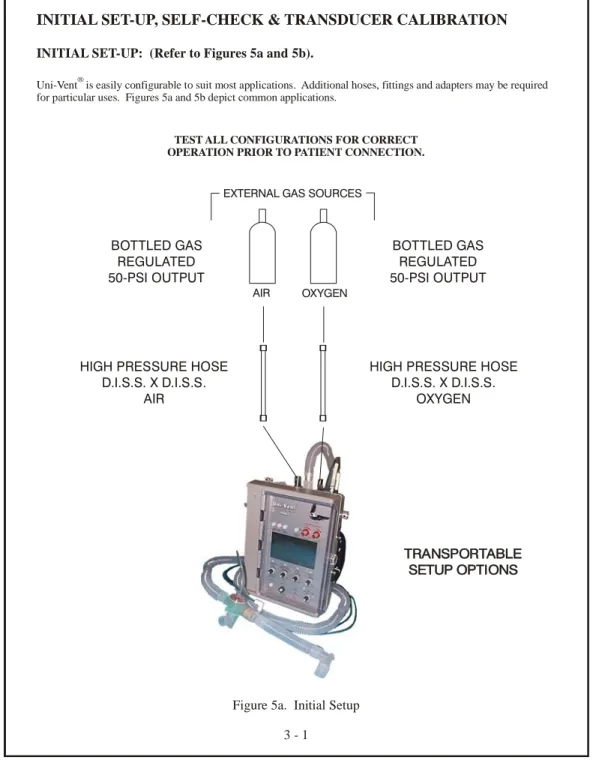
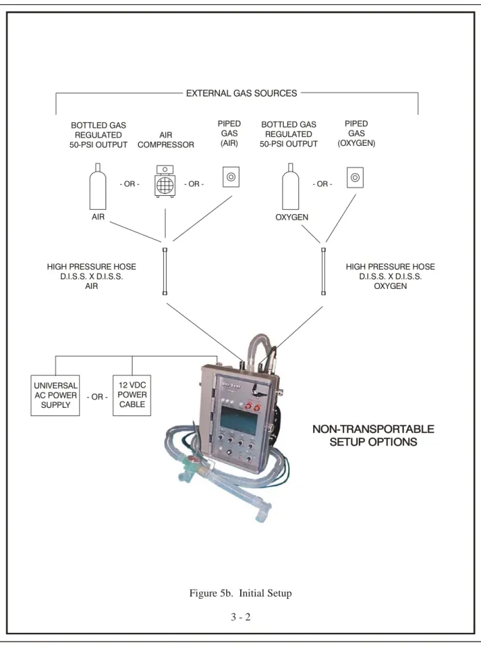
Uni-Vent is easily configurable to suit most applications. Additional hoses, fittings and adapters may be required for particular uses. Figures 5a and 5b depict common applications.
INITIAL SET-UP: (Refer to Figures 5a and 5b).
®
TEST ALL CONFIGURATIONS FOR CORRECT OPERATION PRIOR TO PATIENT CONNECTION.
TRANSPORTABLE SETUP OPTIONS
AIR
EXTERNAL GAS SOURCES
BOTTLED GAS REGULATED 50-PSI OUTPUT
HIGH PRESSURE HOSE D.I.S.S. X D.I.S.S.
OXYGEN BOTTLED GAS
REGULATED 50-PSI OUTPUT
HIGH PRESSURE HOSE D.I.S.S. X D.I.S.S. AIR - OR - OR OR -AIR COMPRESSOR PIPED GAS (AIR) PIPED GAS (OXYGEN)
Figure 5b. Initial Setup 3 - 2 UNIVERSAL AC POWER SUPPLY 12 VDC POWER CABLE OR -NON-TRANSPORTABLE SETUP OPTIONS OXYGEN
SELF-CHECK
Uni-Vent® undergoes a self-checking process every time its MODE Selector Switch is turned from "OFF" to ACV, SIMV, or CPAP; or from CAL to ACV, SIMV, or CPAP. After the initial SELF-CHECK is performed, self-checking is not repeated if the operator turns the MODE Selector Switch to another operating mode position. The SELF-CHECK process consists of interaction between Uni-Vent's microprocessor and peripheral circuitry to verify external power/internal battery status, memory check, pressure transducer calibration and control panel settings.
NOTE
If external oxygen and/or external compressed gas is connected, each gas pressure must be at least 40-PSI (+/- 2-PSI) at the time SELF-CHECK is performed.
WARNING
SELF-CHECK must be performed with the disposable ventilator circuit disconnected from the patient. This insures that the TRANSDUCER connection is open to ambient atmosphere. Ignoring this requirement could cause the SELF- CHECK process to sense a residual airway pressure. Current information is compared to previous calibration information stored in memory. Accordingly, any residual pressure would result in a false reading leading to a SELF-CHECK failure.
Operation begins immediately following SELF-CHECK.
If Uni-Vent® fails SELF-CHECK, a VENTILATOR FAIL Alarm will occur. Return the MODE Selector Switch to its OFF position and then repeat this procedure. If SELF-CHECK fails again, contact qualified service personnel - DO NOT ATTEMPT PATIENT USE.
SELF-CHECK will automatically alert attendant personnel if the pressure transducer calibration "zero" baseline exceeds +/- 1 cmH2O from its last calibration. A TRANSDUCER CALIBRATION Alarm activated during SELF-CHECK will cause an audible tone and the AMC to display:
TRANSDUCER CALIBRATION - - OR - VENTILATOR FAILURE
CALIBRATE TRANSDUCER DETECTED
VENTILATOR FAILURE if SELF-CHECK
DETECTED Alarm is not
related to the
FAILURE CODE 1 Transducer FAILURE CODE 1
• SELF-CHECK FAILURE! Calibration: • SELF-CHECK FAILURE! If only the pressure transducer calibration portion of SELF-CHECK fails, proceed to the section entitled TRANSDUCER CALIBRATION - DO NOT ATTEMPT PATIENT USE.
TRANSDUCER CALIBRATION
The disposable ventilator circuit connects to a pressure-sensing element (transducer) in the ventilator. The transducer, in turn, provides a stream of data to Uni-Vent's microprocessor. Transducer calibration information is stored in a serial, non-volatile EEPROM memory. This information is updated automatically during SELF-CHECK, then every 5-minutes thereafter through Eagle®'s AUTO CAL function, or, it can be manually updated by the user. Transducer calibration is essential for correct operation.
The TRANSDUCER CALIBRATION process calibrates Uni-Vent's internal pressure transducer to atmospheric pressure. During operation, Uni-Vent's microprocessor will respond according to pressure signals from the transducer which are compared to its control panel settings.
TRANSDUCER CALIBRATION, (cont'd) AUTOMATIC CALIBRATION (AUTO CAL)
During operation, Eagle™ performs an automatic calibration of its pressure transducer every 5-minutes. This process maintains a consistent transducer baseline over a wide temperature range to assure display, monitoring, and triggering accuracy. If the baseline drifts significantly since the prior AUTO CAL was performed, or the baseline is unstable, Eagle™ will retry AUTO CAL 1-minute later. If AUTO CAL fails again, a VENTILATOR FAILURE Alarm, CODE 7 is activated to assure patient safety.
MANUAL CALIBRATION
WARNING
TRANSDUCER CALIBRATION, like SELF-CHECK, must be performed with the disposable ventilator circuit disconnected from the patient. This insures that the TRANSDUCER connection is open to ambient atmosphere. Ignoring this requirement would allow the procedure to sense any residual airway pressure in the patient circuit. The residual pressure becomes the new calibration reference (albeit a false reference), which will increase your patient's work-of-breathing by the residual amount.
• 1. Set MODE Selector Switch to CAL. The AMC will display:
Calibration...Please Wait
MODE = CAL
• 2. Calibration will take approximately 3-seconds. When finished, the AMC display will change to: MODE = CAL OK
NOTE
The PIC will display information pertinent to operating power and battery charge status in addition to the above AMC messages.
A TRANSDUCER CALIBRATION ABORT Alarm will occur if the MODE Selector Switch is turned to an operating mode position before CAL is completed. The CAL procedure must be restarted by turning the MODE Selector Switch to any position other than CAL, and then returning it to CAL, and repeating the process described in steps 1, 2 and 3 above. When activated the AMC displays: TRANSDUCER CALIBRATION ABORT -
RECALIBRATE TRANSDUCER or TRANSDUCER CALIBRATION ABORT. The AMC will blank if a SYSTEM FAILURE Alarm occurs.
USER PROGRAMS
The Model 754 contains a USER PROGRAMS menu that allows certain operating characteristics to be changed. Some changes can be stored in Eagle™'s memory - temporary changes are not. Program changes that get stored in memory apply each time the ventilator is operated or, until the user makes a new program change effecting that particular characteristic. Temporary changes are not stored in memory and will last until ventilator power is turned OFF. User programmable/selectable characteristics are: LCD Backlight Threshold default, can not be adjusted for units with serial number greater than 0704001, LCD Contrast default, Trigger Level Sensitivity, Set Spontaneous Flow, Demonstration Mode (DEMO), and TEST BACKUP VENTILATOR.
The bottom line of each menu in USER PROGRAMS contains the following information: "#### Hrs" - where "####" represents cumulative hours of operation since the
last Preventative Maintenance was performed.
USER PROGRAMS, (cont'd)
"### Dys" - where "###" represents cumulative days since the last Preventative
Maintenance was performed
"Version #.##" - where #.## indicates the software version.
To enter the USER PROGRAMS menu, simultaneously press MUTE and MANUAL BREATH/TRIGGER Pushbutton Switches while turning the MODE Control Switch to A/C, SIMV, CPAP, or CAL.
• Follow on screen prompts.
• Press adjacent pushbutton switches to make your selections.
• Press pushbutton switch adjacent to "EXIT" to leave USER PROGRAMS menu and return to selected mode of operation: A/C A/C DEMO SIMV SIMV DEMO CPAP CPAP DEMO CAL
LCD BACKLIGHT THRESHOLD DEFAULT: Backlight can not be adjusted for units with serial number greater than 0704001.
LCD CONTRAST DEFAULT: Controls the LCD's contrast setpoint. Depending upon viewing comfort, user's may choose to increase or decrease color contrast between activated LCD pixels and their background. Any increase or decrease to the setpoint is seen on the LCD. Changes can be stored in memory or temporarily used during the current operating cycle. To store changes in memory, the pushbutton switch adjacent to the on screen "SAVE" prompt must be pressed. If "SAVE" is not pressed, the previously stored setpoint remains.
TRIGGER LEVEL SENSITIVITY: Controls the inspiratory work-of-breathing setpoint for patient-triggered breaths. Eagle™'s default sensitivity is 1.5 to 2.0 cmH2O below end pressure. This USER PROGRAM allows Trigger Level Sensitivity to be temporarily changed until operating power is turned OFF. It is adjustable from 1.0 to 6.0 cmH2O in 0.5 cmH2O increments. For spontaneous breaths occurring in SIMV and CPAP, the sensitivity cannot be set below 2 cmH2O. Sensitivity adjustments to 2 cmH2O, or higher, will affect all breaths. Adjustments made below 2 cmH2O will only affect mandatory breaths. New settings cannot be saved in memory. Once operating power is turned "OFF" Trigger Level Sensitivity is returned to its default value.
NOTE
Under most operating conditions Eagle™'s default Trigger Level Sensitivity should be used. User's are cautioned to carefully consider their operating environment before selecting a different Trigger Level Sensitivity. If 1.0 cmH2O is selected, motion artifact may cause false triggering of breaths. Conversely, selecting a sensitivity above 2.0 cmH2O to compensate for excessive motion artifact, or physiologic conditions, can cause excessive inspiratory work-of-breathing.
USER PROGRAMS, (cont'd)
SET SPONTANEOUS FLOW: Eagle™'s default Spontaneous Flow is 60 LPM. This USER PROGRAM allows Spontaneous Flow (for use in SIMV or CPAP) to be temporarily changed until operating power is turned OFF. It is adjustable from 10 to 60 LPM in 5 LPM increments. New settings cannot be saved in memory. Once operating power is turned "OFF", Spontaneous Flow is returned to its default value.
DEMONSTRATION MODE (DEMO): Permits user's to operate this device in a mode that is quite helpful for demonstration/training purposes. DEMO mode allows user's to make settings, adjustments, trigger alarms, and view simulation waveforms on Eagle™'s LCD. DEMO mode does not allow Disconnect Alarm activation or Proximal Pressure Transducer operation.
WARNING
DEMO mode is not for patient use. Once operating power is turned "OFF" DEMO mode is cancelled.
TEST BACKUP VENTILATOR: Permits user to test the BACKUP VENTILATOR and MANUAL TRIGGER. Activating the BACKUP VENTILATOR will cause it to function as described in the section entitled BACKUP VENTILATOR. To leave the BACKUP VENTILATOR function and return to normal operation, turn the MODE Control Switch to "OFF" then "ON" to desired operating mode.
MODES OF OPERATION
Your Model 754 has been carefully designed to ease the learning transition commonly associated with new instruments. In addition to its clean, uncluttered appearance, Uni-Vent®includes numerical panel markings to simplify and speed start-up. Only the five primary controls, common to most applications, are marked. They are numbered in order of use, in a 5-step sequence. It is possible to initiate operation using as few as 3-controls.
• Step 1: Select operating mode; ACV, SIMV or CPAP
• Step 2: Set VENTILATION RATE
• Step 3: Set INSPIRATION TIME NOTE
If your protocol calls for use only at the 1:2 I:E RATIO preset, Step 3 can be bypassed.
• Step 4: Set TIDAL VOLUME
• Step 5: Set the AIR/OXYGEN MIXER for an FIO2 between 21 and 100 NOTE
If your protocol involves use without external oxygen, or with 100% oxygen, the AIR/OXYGEN MIXER control remains either fully counterclockwise or fully clockwise and control #5 can be bypassed.
Control panel settings may be adjusted at any time. In normal use, adjustments are typically made immediately following SELF-CHECK, however, the 1:2 I:E RATIO and extents for FIO2 and PRESSURE ALARMS may be preset.
The Model 754 can operate in the following modes:
ASSIST-CONTROL VENTILATION: WITH/WITHOUT PEEP, WITH/WITHOUT SIGH
ASSIST-CONTROL VENTILATION: WITH/WITHOUT PEEP, WITH/WITHOUT PRESSURE PLATEAU
SYNCHRONIZED INTERMITTENT MANDATORY VENTILATION: WITH/WITHOUT PEEP, WITH/WITHOUT SIGH
SYNCHRONIZED INTERMITTENT MANDATORY VENTILATION: WITH/WITHOUT PEEP, WITH/WITHOUT PRESSURE PLATEAU CONTINUOUS POSITIVE AIRWAY PRESSURE: WITH/WITHOUT PEEP
CONTROL VENTILATION (apnea backup of ACV, SIMV and CPAP) CONTROL VENTILATION (backup ventilator)
WARNING
Functions which are dependent upon accurate pressure readings should only be used in conjunction with a protected airway. This will prevent "leaks" from distorting pressure signals. DO NOT use pressure dependent functions with an unprotected airway. This applies primarily to use with uncuffed endotracheal tubes, uncuffed tracheostomy tubes, and resuscitation masks where the face-to-mask-seal integrity is frequently and typically compromised.
MODES OF OPERATION, (cont'd)
IMPORTANT NOTEThe Model 754 includes preset trigger sensitivity default.
Preset trigger sensitivity default is set between 1.5 and 2.0 cmH2O below end pressure. Triggering sensitivity determines how much negative deflection a spontaneously breathing patient must generate before Uni-Vent® initiates a mechanical breath or demand flow. In the Model 754, triggering sensitivity is both automatic and PEEP compensated. To change trigger sensitivity, or Spontaneous Flow for SIMV and CPAP, see section entitled (USER PROGRAMS).
During operation Uni-Vent's preset trigger looks for the next spontaneous breath to reach its trigger threshold. For whatever reason, if a spontaneous breath is in process when the trigger is activated, the following conditions prevail:
• If the patient's inspiratory pressure has not reached the trigger threshold, Uni-Vent® will trigger when the threshold is reached.
• If the patient's inspiratory pressure has exceeded the trigger threshold, Uni-Vent® will wait until the next spontaneous inspiration reaches threshold before triggering.
IMPORTANT NOTE
ACV, SIMV and CPAP ventilations are continuously monitored. Should apnea occur in one of these modes, Uni-Vent's microprocessor will activate applicable alarms and initiate control ventilations (see section entitled CONTROL VENTILATION DURING APNEA).
NOTE
Uni-Vent® includes built-in altitude compensation. Once you've performed a TRANSDUCER CALIBRATION, changes in altitude will have no effect upon pressure-related performance.
NOTE
Uni-Vent® has been certified by an independent testing laboratory to meet electromagnetic interference (EMI) and radio frequency interference (RFI) shielding requirements. Certification includes both radiated emissions and conducted susceptibility.
ASSIST-CONTROL VENTILATION (ACV)
In ACV, Uni-Vent® is configured to deliver a minimum ventilatory rate, preset inspiration time and preset tidal volume. Patient-initiated breaths, sensed by negative pressure deflection, cause Uni-Vent® to trigger an "assisted" ventilation that is equal to its INSPIRATION TIME and TIDAL VOLUME settings. Controlled ventilations are delivered when there are no spontaneous respiration's or the patients' spontaneous ventilation rate attempts to fall below the current VENTILATION RATE setting. If this occurs, controlled ventilations are delivered at the VENTILATION RATE, INSPIRATION TIME and TIDAL VOLUME settings.
Should the patient become apneic in the ACV mode, Uni-Vent® will activate its APNEA Alarm and automatically begin controlled ventilations at its current VENTILATION RATE/INSPIRATORY TIME/TIDAL VOLUME control settings or 12 ventilations per minute/INSPIRATORY TIME/TIDAL VOLUME control settings - whichever is greater (see section entitled CONTROL VENTILATION DURING APNEA; APNEA DURING ACV OR SIMV
OPERATION).