3300
IP Communications Platform
Technician’s Handbook
respects but is not warranted by Mitel Networks™ Corporation (MITEL ). The information is subject to change without notice and should not be construed in any way as a commitment by Mitel or any of its affiliates or subsidiaries. Mitel and its affiliates and subsidiaries assume no responsibility for any errors or omissions in this document. Revisions of this document or new editions of it may be issued to incorporate such changes.
No part of this document can be reproduced or transmitted in any form or by any means - electronic or mechanical - for any purpose without written permission from Mitel Networks Corporation.
Trademarks
Mitel, SX-2000, SUPERCONSOLE 1000, and SUPERSET are trademarks of Mitel Networks Corporation.
Windows is a trademark of Microsoft Corporation. Cisco is a trademark of Cisco Systems, Inc.
VT100 is a trademark of Digital Equipment Corporation. Java is a trademark of Sun Microsystems Incorporated.
Other product names mentioned in this document may be trademarks of their respective companies and are hereby acknowledged.
3300 IP Communications Platform Technician’s Handbook
Mitel Communications Director (MCD) Release 5.0 57011493, Rev A
2011
Trademark of Mitel Networks Corporation ©Copyright 2011, Mitel Networks Corporation
Chapter 1 : Getting Started
Purpose of This Handbook ...3
Documentation for Unsupported Controllers ...3
Symbols Used in the Handbook ...3
Safety Instructions ...3
Start Here Guide ...5
What You Received ...5
What You Need for Installation ...5
Preparation ...5
Initial Setup ...6
Install Hardware ...6
Program System ...6
Install System Software ...6
Maintain System ...7
Install and Replace Units ...7
About the 3300 ICP ...8
3300 ICP Documentation - Mitel eDocs ...8
Contacting Mitel ...9
Chapter 2 : Initial Setup Connect PC to Controller ...13
PC Requirements ...13
AX, MXe, CX, CXi, CX II and CXi II Controller ...13
Power Up the Controller ...14
MXe Server ...14
Licensing the MXe Server with AMC ...23
Setting your DNS Server IP ...24
Verify the Connections ...24
Establish Communication with Controller ...25
Set Controller RTC IP Address (AX, MXe, CX, CXi, CX II, CXi II) ...25
Configure System IP Address (MXe Server) ...26
Configure the Layer 2 Switch (AX, MXe, CXi, CXi II) ...26
Configure the Layer 2 Switch (MXe Server) ...27
Enable Licenses and Options ...29
Automatic Sync with AMC via MCD Software Installer Tool (Rel 6.0 or later) ...31
Automatic Sync via System Administration Tool ...33
Manual License and Options Entry via MCD Software Installer Tool ...34
Manual License and Options Entry via System Administration Tool ...35
Install the Online Help (Optional) ...36
Verify the Operation of the Controller ...37
Chapter 3 : Installation and Programming Install Hardware ...41
Determine Controller Module Configuration ...41
Identify Controller Component Options ...45
Install Controller Modules ... 48
Install Controller Stratum 3 Clock Module ... 51
Install Controller Hardware ... 51
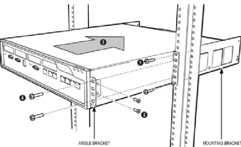
Rack Mount the Controller ... 51
Wall Mount the CX/CXi and CX II/CXi II Controller ... 56
Install Service Units and Cabinets ... 58
Installing SX-200 Bays ... 62
Install Telephones ... 64
Install and Configure Music on Hold ... 65
Program 5485 IP Paging Unit ... 66
Register IP Devices from the Telephone ... 67
Program System ... 70
Programming Tools ... 70
Log into the Programming Tools ... 71
Configure NSU via IMAT ... 73
Program the Controller DHCP Server (MXe, CX/CXi, CX II/CXi II) ... 76
Program LS Trunk Settings via LS Measure Tool ... 78
Configure Analog Music On Hold/Paging ... 79
Chapter 4 : Software Installation About Installing and Upgrading Software ... 83
Install System Software Manually ... 85
The MCD Software Installer Tool ... 91
Install the MCD Software Installer Tool ... 91
Install System Software using the Software Installer ... 91
Upgrade System Software ... 94
Online Upgrade ... 94
Offline Upgrade ... 98
System Software Installation Details ... 101
Software Upgrade/Install Options ... 101
Upgrading System Software - Notes, Tips, and Cautions ... 102
Change Number of IP User Licenses ... 103
Cluster or Dimension Changes ... 103
Installing MSL Software on APC (CX/CXi) or APC-CX(i) II (CX II/CXi II) ... 105
Installing MSL Software on an MXe Server ... 106
Installing System Software on the FTP Server ... 106
Upgrade to MCD 5.0 and Group Licensing ... 107
Upgrade the 3300 ICP Software on the MXe Server ... 108
Upgrading/Installing with Maximum Elements Change ... 108
Upgrade to Rel 6.0 or later with Flexed Dimensions ... 110
Apply a Software Patch ... 111
Distributing New Firmware to IP Phones ... 112
Load IP Phone Software Remotely ... 112
Chapter 5 : Maintenance
Check System ...117
Check Alarm State ...117
Check System Health ...117
Check Controller Hardware Profile ...118
Maintain VoIP Security ...118
View Logs ...119
View Maintenance or Software Logs ...119
Collect System Logs ...119
View Logs Remotely, TCP/IP Socket Numbers ...121
View Login and Logout Audit Logs ...122
Downloading MXe Server Logs ...122
Detect Device Moves for E911 ...123
Monitor Device Moves ...123
Detecting Device Moves ...126
Viewing Device Connectivity Logs ...126
Analyze IP Phone Issues ...127
Power Down the Controller ...129
Perform a System Reset ...129
Back Up a Database ...130
Restore a Database ...132
Migrate SX-2000 Database Across Platforms ...136
Converting a PRI Database on a Universal NSU ...138
Export Configuration Data ...139
Import Configuration Data ...140
Restoring Default Addresses on MXe Server ...141
Assign Static IP Addresses to IP Phones ...142
Providing Power Over Ethernet to Devices (CXi/CXi II) ...145
Recover MXe Server ...146
Before You Begin ...146
Install Replacement Hardware ...146
Connect Laptop PC and CD/DVD Drive ...147
Install Mitel Application Server Software ...148
Configure MAS Parameters ...149
Configure Server Manager Fields ...150
Reset MXe Server System IP Address to default ...155
Chapter 6 : Install and Replace Units Component Replacement Notes ...159
MXe and MXe Server ...160
Add or Replace Controller FRUs ...166
Controller Modules ...168
Adding or replacing controller modules ...168
AX Controller ...169
Controller Module Installation Notes ...170
Stratum 3 Clock Module ...173
Analog Main Board ... 175
MXe ... 175
CX/CXi ... 176
CX II/CXi II ... 178
Analog Option Board ... 179
CX/CXi ... 179
CX II/CXi II ... 180
Configure Embedded Analog Boards ... 183
Application Processor Card ... 184
APC-MXe Server ... 184
APC-CX(i) ... 188
APC Hard Drive (CX/CXi) ... 192
APC-CX(i) II Assembly ... 194
E2T or RTC Processor ... 202
Hard Drives ... 205
Hard Drive Replacement Overview ... 205
CX/CXi ... 205
CX II/CXi II (Hard Disk or Solid State Drive) ... 207
LX ... 208
MXe II (Single Hard Disk or Solid State Drive) ... 209
MXe II/MXe Server (Two Hard Drives) ... 210
MXe III (Single Hard Disk or Solid State Drive) ... 214
MXe III (Two Hard Drives) ... 215
Fan Complex ... 218
MXe/MXe Server ... 218
AX ... 219
CX II/CXi II ... 220
Power Supply Unit ... 221
MXe, AX ... 221
ASU II ... 221
Redundant Power Supply ... 222
AX, MXe, MXe Server ... 222
RAID Controllers ... 223
MXe II/MXe Server ... 223
MXe III ... 226
Line Cards ... 231
AX ... 231
ASU II ... 231
Controller Card (AX) ... 232
Flash Cards (AX) ... 233
Memory Module (CX, CXi, AX) ... 235
Install Cabinet FRUs ... 236
Appendix A : Hardware Reference System Configurations ... 239
Dual T1/E1 Framer ...250
Quad BRI Framer ...250
Analog Board (CX/CXi, CX II/CXi II, and MXe Controllers) ...251
Line Cards (AX Controller) ...253
Controller Alarm Port Pinouts ...253
Controller Remote Alarm Behavior ...253
Network Services Units ...254
Universal/R2 NSU ...254
BRI NSU ...258
Analog Services Unit ...260
5485 IP Paging Unit ...266
SX-200 Bay ...267
Appendix B : Installation Planner Reserved IP Addresses ...271
MXe Server/MXe/AX/CXi/CXi II Requirements for IP Networking ...272
Controller Configuration Settings (RTC) ...275
DHCP Configuration Settings ...276
Programming E2T via Debug Cable or Secure Telnet ...282
Configuring External DHCP Settings for E2T ...283
Configuring a Windows 2000 or Windows 2003 DHCP Server (Rel 7.0 and later) ....284
System Administration Tool Settings ...286
IP Phone Settings ...286
Telephone Programming Guide ...286
Increasing DSP Resources ...287
Appendix C : Typical Network Configurations Network Configuration Examples ...301
DHCP Server Settings ...301
Configuration 1: One DHCP Server per VLAN ...302
Configuration 2: One DHCP Server for Two VLANs ...304
Configuration 3: Router on a Stick ...305
LLDP-MED and IP Phone Network Policy ...305
Cisco Discovery Protocol (CDP) ...306
CXi/CXi II/MXe/MXe Server Configuration ...307
Firewall/Port Forwarding ...307
PPTP Remote Access ...307
WAN Settings (Internet Gateway) ...307
Configuration A: CXi/CXi II/Typical Voice-Only Network ...308
Configuration B: MXe Typical Voice-Only Network ...309
Configuration C: CXi/CXi II Typical Voice and Data Network ...310
Configuration D: MXe Typical Voice and Data Network ...311
AX Configuration Procedures ...312
AX Typical Voice-Only Network ...312
AX Typical Voice and Data Network ...313
CXi, CXi II, MXe and AX-Specific Guidelines ...314
Implementing a Voice-Only Network ... 317
Implementing a Voice and Data Network ... 319
Installing External Layer 2 Switches ... 322
Windows 2000 FTP Server ... 326
Appendix D : Status LEDs Controller LEDs ... 332
Controller Alarm LEDs (AX, MXe/MXe Server) ... 336
Controller Power LED (AX, MXe/MXe Server, CX/CXi, CX II/CXi II) ... 336
Hard Drive or Flash Activity ... 336
RAID Controller ... 337
FIM ... 340
LAN Ethernet Ports ... 341
CIM, Embedded and Quad MMC ... 342
Controller Alarm ... 342
Power Supply Unit LEDs ... 345
Dual T1/E1 Framer Module ... 345
T1/E1 Combo Card ... 346
Quad BRI Framer Module ... 347
Network Services Unit LEDs ... 349
Universal/R2 NSU ... 349
BRI NSU ... 352
Analog Services Unit LEDs ... 354
ASU II Card LEDs ... 356
ASU II ONS and Combo Card Alarm LED ... 356
ASU II ONS Card Activity LED ... 356
ASU II Combo Card Activity LED ... 356
IP Device LEDs ... 357
Peripheral Cabinet LEDs ... 358
SX-200 Bay LEDs ... 360
Digital Services Unit LEDs ... 363
In-Line Power Unit LEDs ... 366
Appendix E : FRU Part Numbers Hardware Part Numbers ... 371
Software Part Numbers ... 378
Appendix F : System Capacity and Parameters System Parameters ... 383
Port Usage ... 383
Encryption Support ... 384
IP Set Features ... 385
IP Phone Power Consumption ... 386
Capacity ... 387
Appendix G : Older Hardware and Software
Procedures for Older Controllers ...395
Programming the Controller DHCP Server Settings (prior to Rel 7.0) ...395
To use an alternative DHCP server (prior to Rel 7.0) ...396
Configuring a Windows 2000 DHCP Server (prior to Release 7.0) ...397
Program DHCP for VLAN (prior to Rel 7.0): ...399
Connect a Windows 95/98 PC to the NSU via Dial-Up ...401
Physically Connecting the PC to an NSU ...402
Creating a Dial-Up Network Connection on Windows 95/98 ...402
Migrate SX-2000 PBX Hardware ...404
Collecting System Logs Manually ...405
Collecting System Lockup Logs Manually ...406
Peripheral Cabinet ...407
Digital Service Unit (DSU) ...407
Purpose of This Handbook
This handbook provides certified 3300 ICP technicians with instructions to install, upgrade, maintain and troubleshoot the Mitel® 3300 IP
Communications Platform (ICP). For information on programming, please refer to the System Administration Tool Help system.
Documentation for Unsupported Controllers
This document covers controllers supported by MCD Release 4.0 and higher. For controllers, such as MX, 100-, 250-, and 700-user controllers, that are not covered here, refer to earlier versions of the Technician’s Handbook.
Symbols Used in the Handbook
Safety Instructions
A printable version of the Safety Instructions is available on the Mitel Customer Documentation web site.
Note:Provides important details.
Tip:Provides additional information you should know about a topic.
Time: Indicates the time it takes to complete a procedure.
CAUTION: Indicates a potentially hazardous situation that could result in damage to the equipment.
CAUTION: Read the safety instructions before performing the procedures in this handbook.
CAUTION: Failure to follow all instructions may result in improper equipment operation and/or risk of electrical shock. Refer to “3300 Safety Instructions” for complete safety infor-mation.
CAUTION: To prevent ESD damage to the equipment: (1) Ensure that the system is grounded before you install a card. (2) Whenever you handle cards, wear an anti-static strap (attached to the cabinet). (3) When removing cards from the cabinet, immediately place them in an anti-static bag.
CAUTION: All installation, field replacement, and servicing procedures must be carried out by service personnel who have successfully completed the Mitel Installation and main-tenance training course.
CAUTION: Hardware is sensitive to shock and vibration; han-dle hardware with care.
CAUTION: Provide a permanent ground for all controllers and units through the ground connection on each cabinet. CAUTION: BRI Interface is not available in Taiwan. Use of this interface is prohibited.
CAUTION: When sold in Taiwan, the MXe Controller supports ISDN T1/E1 and Leased Line T1. However, it does not support Leased Line E1 and ISDN BRI in Taiwan.
Note: The ground symbol within a circle identifies the terminal to be connected to an external protective conductor. Connect this terminal to earth ground before you make any other connections to the equipment.
Start Here Guide
What You Received
3300 ICP Controller
• Set of feet and rack mounting hardware Hardware Components
• System i-Button (except in MXe Server)
• Hard drive (ordered separately for MXe, CX, CXi, CX II and CXi II) or Compact Flash Card (AX only)
Software
• MXe, CX, CX i CX II and CXi II: provided on separately ordered hard drive; see Appendix E on page 369 for part numbers.
• AX and MXe Server: Mitel Communications Director Installation CD (included with controller)
Optional Hardware, such as
• RAID Hardware and hard drives (2)
• Redundant Power Supply
• NSU, ASU
What You Need for Installation
Phillips screwdrivers Anti-static strap
CAT 5 or better cable with RJ-45 connector Computer for programming the 3300 ICP
IP addresses for the controller, E2T, and IP telephones List of purchased options and password
IMAT (not required for embedded PRI)
Preparation
Review your purchase order
Review Appendix C: “Typical Network Configurations” on page 299
Initial Setup
“Connect PC to Controller” on page 13
“Establish Communication with Controller” on page 25 “Enable Licenses and Options” on page 29
Install Hardware
“Determine Controller Module Configuration” on page 41 “Identify Controller Component Options” on page 45 “Remove Controller Cover” on page 47
“Install Controller Modules” on page 48
“Install Controller Stratum 3 Clock Module” on page 51 “Install Controller Hardware” on page 51
“Rack Mount the Controller” on page 51 “Install Service Units and Cabinets” on page 58 “Install Telephones” on page 64
“Install and Configure Music on Hold” on page 65 “Register IP Devices from the Telephone” on page 67
Program System
“Log into the Programming Tools” on page 71 “Configure NSU via IMAT” on page 73
“Program the Controller DHCP Server (MXe, CX/CXi, CX II/CXi II)” on page 76
“Program LS Trunk Settings via LS Measure Tool” on page 78 “Configure Analog Music On Hold/Paging” on page 79
Install System Software
- “Install System Software using the Software Installer” on page 91 Upgrade system software:
- “Online Upgrade” on page 94
- “Offline Upgrade” on page 98
“Installing MSL Software on APC (CX/CXi) or APC-CX(i) II (CX II/CXi II)” on page 105
Maintain System
“Back Up a Database” on page 130
“Migrate SX-2000 Database Across Platforms” on page 136 “Export Configuration Data” on page 139
“Import Configuration Data” on page 140
“Assign Static IP Addresses to IP Phones” on page 142 “View Logs” on page 119
“Detecting Device Moves” on page 126
“Load IP Phone Software Remotely” on page 112 “Assign Static IP Addresses to IP Phones” on page 142 “Perform a System Reset” on page 129
“Restore a Database” on page 132 “Recover MXe Server” on page 146
Install and Replace Units
“Component Replacement Notes” on page 159 “Add or Replace Controller FRUs” on page 166 “Add or Replace Controller FRUs” on page 166
About the 3300 ICP
The 3300 ICP is a Voice over IP solution that delivers robust call control, extensive features and supports a wide range of desktop devices and applications for medium-to-large enterprises. There are several system configurations:
• the CX and CX II with embedded analog
• the CXi and CXi II with embedded analog and embedded Layer 2 switch for sites with 8-100 lines (150 on CXi II);
• the MXe base with embedded analog supports 300 users before expansion;
• the expanded MXe supports 1400 users;
• the AX controller delivers an increased density of analog devices;
• the MXe Server provides capacity for up to 5000 simultaneous users.
3300 ICP Documentation - Mitel eDocs
For customer documentation, including Knowledge Base Articles, on all Mitel products go to the Mitel Edocs web site at http://edocs.mitel.com.
Access Your Mitel Options Password
You must obtain your Mitel Options Password through Mitel OnLine (www.mitel.com). You will create your application record on the AMC via Mitel Online (see “Enable Licenses and Options” on page 29). This password is required during a software upgrade or installation procedure. A new password has been issued to you if you are purchasing new options. Mitel recommends using online synchronization with the AMC to update your password. Using online synchronization will allow you to license your controller software and options immediately. Remember to print a record of your options for future reference.
If you do not have internet access where your controller is located:
Connect to AMC at Mitel Online and choose the manual licensing option. When you print your options page, it will include your password and Applications Record ID (ARID). Use this password when installing the
Tip:You must have a Mitel OnLine (MOL) account to access technical documentation on Mitel Edocs. Access to end-user documents, such as telephone user guides, does not require an MOL account.
To upgrade software, confirm a current password, or purchase new options and receive a new password, use the AMC at Mitel Online any time.
Contacting Mitel
Order Desk
You can reach the Order Desk at 1-800-796-4835.
Repair Services Department
You must get a Return of Merchandise Authorization (RMA) form from the Repair Services Department before sending equipment back to Mitel. If you are in North America, you can reach the Repair Services Department at 1-888-222-6483.
If you are in any other region, contact your local regional support service.
Technical Support
Please contact Mitel Technical Support if you require technical assistance. If you cannot resolve the problem by using the 3300 ICP Troubleshooting Guide, please collect the required information listed in the applicable section(s) of the 3300 ICP Troubleshooting Guide before calling Mitel Technical Support.
If you are in North America, you can reach Technical Support at 1-800-561-0860 or 1-613-592-2122.
If you are in any other region, contact your local regional support service. For regional contact information, follow the “Contact Us” link at Mitel.com.
Connect PC to Controller
To configure the system, you must connect a PC to the controller.
PC Requirements
You need a Windows-based computer to program, maintain and troubleshoot the 3300 ICP, and to install/upgrade the MCD software.
Computer Recommendations
• Windows® NT 4.0, Windows 2000, Windows XP, or Windows Vista Business or Ultimate.
Computer Requirements
• Windows 98, Windows NT 4.0, Windows 2000, Windows XP, or Windows Vista.
• Network interface card (NIC)
• 1 GB free disk space (minimum)
• Internet Explorer 6.0, 7.0 or 8.0 with the latest Service Pack and 128-bit encryption. (IE 7.0 or 8.0 can be used with Rel 7.1 UR2 and later.)
• JRE (Java Run-time Environment) 1.6.0_1 or later installed
• VT100™ emulator program
• FTP Server (can be installed with Microsoft® IIS or PWS, for example)
AX, MXe, CX, CXi, CX II and CXi II Controller
1. Connect an RS-232 straight DTE male to female serial cable between the controller’s Maintenance port and the PC’s serial port (cable not provided).
2. Program the PC’s serial port (from the communication program) with the following settings:
- Baud Rate: 9600 - Stop Bits: 1
- Data Bits: 8 - Flow Control: None - Parity: None
Tip:Windows 98 with PWS does NOT include an FTP server application required for installations of 3300 ICP Software before Rel 8.0, and will not work for the software installation/upgrade process unless a third-party server application is used. If you are upgrading Rel 8.0+ software on a Rel 8.0 or 8.0+ system, you don’t need an external FTP server.
3. Connect a straight-through Ethernet cable (RJ-45) from the controller leftmost Ethernet port (port 17 on the CXi and CXi II; port 1 on the CX, CX II, MXe, and MXe Server) and the PC’s network interface card (NIC). When connecting to the AX, either Ethernet port will work.
4. Program the PC’s NIC with the following settings:
- IP Address: 192.168.1.n (where n is a value between 30 and 254)
- Subnet Mask: 255.255.255.0
Power Up the Controller
1. Connect the female end of the power cable to the controller, and secure it with the latch (if provided).
2. Connect the other end of the power cable to a protected outlet. Turn on power switch (MXe, MXe Server, CX/CXi, and CX II/CXi II). If there are two power supplies, ensure that both power switches are turned on. The controller starts up.
3. Proceed to “Establish Communication with Controller” on page 25
MXe Server
Unlike the other 3300 ICP controllers, the MXe Server arrives complete, with all of the software pre-installed on the hard disk. This includes the Mitel Communications Director (MCD) software and the VxWorks virtual machine. There is still some configuration and licensing work to do before the MXe Server can be used in your network, though, and the instructions are provided in this section.
The MXe Server is shipped with an Application Processor Card (APC-MXe) that runs the MCD call control software. Also included standard on the MXe Server are the RTC and the E2T cards. All of these processors must be able to communicate with each other, so IP addresses must be assigned to all of them.
Note:For the MXe Server, the controller IP is the System IP address; default 192.168.1.5. Reserve 8 consecutive IP addresses for the MXe Server.
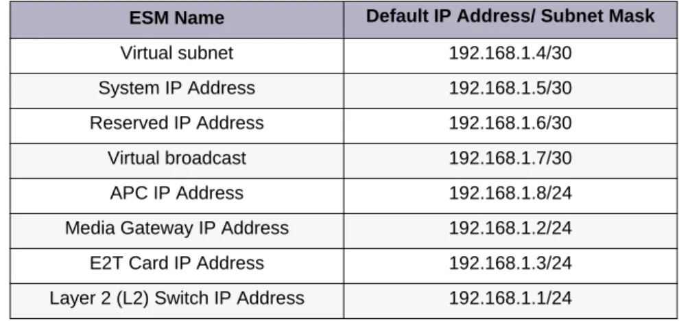
The MXe Server is shipped with default IP addresses assigned. The defaults are shown in Table 1.
Before You Begin
To complete this procedure, you will require Laptop
Communications application (for example, Hyperterminal) RS-232 serial cable
Ethernet cable (straight-through) MCD Software Installer tool
Application Record Identification Number (AMC ARID)
Tip:If you are replacing an existing 3300 ICP controller with an MXe Server and you want to use the same system IP address for the MXe Server, initially you will only be able to connect to the MXe Server from the local subnet. Before you can connect to the MXe Server from other subnets, you must manually clear the router ARP cache or wait until the router ARP cache is automatically updated. Refer to the latest 3300 ICP Release Notes for instructions.
Tip:The MXe Server is shipped with two hard drives, one with the software loaded and one blank. Before continuing, mirror the blank drive starting at Step 11 of the procedure described in “Replace One Hard Drive in an MXe II/MXe Server” on page 210.
Table 1: Default IP Addresses for the MXe Server
ESM Name Default IP Address/ Subnet Mask
Virtual subnet 192.168.1.4/30
System IP Address 192.168.1.5/30
Reserved IP Address 192.168.1.6/30 Virtual broadcast 192.168.1.7/30
APC IP Address 192.168.1.8/24
Media Gateway IP Address 192.168.1.2/24 E2T Card IP Address 192.168.1.3/24 Layer 2 (L2) Switch IP Address 192.168.1.1/24
Connect Laptop PC
1. Power up the MXe Server and wait approximately 3 minutes for the software to enable the printer port.
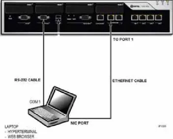
2. Connect the RS-232 serial cable between the COM 1 port on your laptop to the server printer port (see Figure 1).
Figure 1: Laptop Connections
3. Open a communication application (for example ProCom or
Hyperterminal) on your laptop to the 3300 ICP and set the connection parameters as follows:
Table 2: Communication Connection Parameters
Parameter Required Setting
Port COM 1 (example only)
Bits Per Second 38400
Data Bits 8
Parity None
Stop Bits 1
Configure MAS Parameters
4. After the Server Console screen appears, you are prompted to accept the End-User License Agreement. Select Accept.
5. In the configuration screens, select the following settings:
Table 3: MAS Configuration Parameters
Configuration Screen Required Setting
Restore from Backup (this screen relates to a backup of the Linux database)
Select No.
Choose Linux Admin Password Enter a password. Then, enter it again to verify it. Note that passwords are case-sensitive. Also, see Caution below this table.
Select Primary Domain Name Enter name (for example mitel.com) Select System Name Enter name (for example the company
name) Enter Local Networking Parameters (local IP address for this server)
Enter 192.168.1.8
(INITIALLY, KEEP AS DEFAULT!!!) Select Local Subnet Mask (see Note
below)
Enter 255.255.255.0 Select Operating Mode Select Server-only
Select Gateway Address Enter 192.168.1.1 (INITIALLY, KEEP AS DEFAULT!!!)
Set DHCP Server Configuration Select Off - Do not provide DHCP Service to local Network
Corporate DNS Server Address Enter your corporate DNS server IP address.
Application Record ID Leave field blank. Click Next. Activate Configuration changes Select Yes
Note:Use 255.255.255.0 unless your network requires a different subnet
mask. If your network requires a different Local Subnet Mask, change it now. You can only change the subnet mask through the server console. In the MAS Server Manager application, the subnet mask is a read-only field.
Configure Server Manager Fields
6. Connect the ethernet cable from the Network Interface Card (NIC) connector on your laptop to Port 1 of the MXe Server.
7. On your laptop set the NIC IP address to 192.168.1.20. The following steps are for Windows 2000 or Windows XP operating systems:
- Click Start, click Settings, click Network and Dialup
Connections, and then click Local Area Network Connection
- Select Internet Protocol (TCP/IP) - Click Properties
- Select Use the following IP address - Enter the following IP address: 192.168.1.20
- Enter Subnet Mask (use the same Subnet Mask that you configured for the APC)
- Click OK
- Click Start, click Settings, click Network and Dialup
Connections, and then click Local Area Network Connection.
Ensure that the connection is Enabled.
8. Launch Microsoft Internet Explorer and go to the following URL: https:/192.168.1.8/server-manager.
9. At the login page, enter Username: admin
Password: (enter the Linux admin password that you set through the Server Console). The Managed Application Server Manager
application opens.
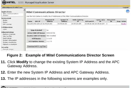
10. Under Applications, click Mitel Communications Director. The Mitel Communications Director screen is displayed:
CAUTION: Ensure that you record your Linux Admin pass-word. If you lose this password, it cannot be recovered. You will have to re-install the MAS software and set a new pass-word.
Figure 2: Example of Mitel Communications Director Screen 11. Click Modify to change the existing System IP Address and the APC
Gateway Address.
12. Enter the new System IP Address and APC Gateway Address.
13. The IP addresses in the following screens are examples only.
14. Click Next. After you click Next, you should see a message stating that the addresses were successfully modified displayed in green text. The system automatically reserves four IP addresses that are required to support the system in the network. These addresses must be valid, contiguous, and available in the network.
.
Figure 4: Enter the New Addresses
15. Enter three, valid, available, and contiguous IP addresses for the
- Media Gateway IP (IP address of the Real Time Controller card)
- E2T Card IP
- Layer 2 (L2) IP
16. Enter the Voice VLAN ID (1 to 4093), if required for the network. At the bottom of the Mitel Communications Director screen, the following information is displayed:
latest upgrade. On an initial installation of the 3300 ICP, this field displays "Not Installed".
MCD Version: current Mitel Communications Director software
version that was installed using the Software Installer tool. It is NOT the software version of the MCD blade software.
Swap: reboots the call server with the currently inactive software version. The currently active version becomes the inactive software version after the reboot. Swap is only displayed if an Inactive version of the 3300 ICP software is installed.
Do not enable the Swap option during this procedure.
17. Click Save. The E2T and RTC cards are updated with the new IP addresses, subnet mask, and VLAN ID.
18. Open a communication application (for example ProCom or
Hyperterminal) on your laptop to the 3300 ICP and set the connection parameters (see Table 2). Log in to the server console again.
Login: admin
Password: (enter the Linux admin password)
19. Select “Configure this server”. Press the Tab keyboard key until “Local Networking Parameter” is displayed.
20. Enter the IP address of the APC-MXe card that is appropriate for your network. The Gateway IP address changes to x.x.x.1.
21. Press the Tab keyboard key until the Reboot screen appears.
22. Reboot the server.
23. Change the address of the laptop’s Network Interface Card (NIC) back to the IP address for your network. The following procedure is for Windows 2000 or Windows XP:
- From the Windows Start menu, click Settings, click Network and Dial-up Connections, and then click the Local Area Network of the laptop NIC card.
- Click Properties.
- Select Internet Protocol (TCP/IP).
- Click Properties.
- Click “Use the following IP Address” option.
- Click OK.
- In the Network and Dial-up Connections window, right-click on the connection for the laptop NIC and click Enable.
You can now connect to the Mitel Communications Director through gigabit ethernet Port 1 of the MXe Server.
24. Launch Microsoft Internet Explorer and go to the following URL: https:/<your APC IP>/server-manager.
25. At the login page, enter Username: admin
Password: (enter the Linux admin password that you set through the server console). The Server Manager application opens.
26. If the PC that you use to run the MCD Software Installer is not installed on the same network as the MXe Server, you must add the network. Under Security, click Local Networks and add the IP address of the network. Also add the networks of any other Mitel applications or tools, such as OPS Manager, Enterprise Manager, system administrator client stations and so forth that require access to the MXe Server. To extend privileges to a network:
- Under Security, click Local networks.
- Click Add network.
- Enter the Network Address.
- Enter the Subnet Mask.
- Enter the Router.
- Click Add.
27. If the system is connected to the internet, the date and time is set automatically from a Network Time Server. Optionally, you can set the date and time manually:
- Under Configuration, click Date and Time.
- Click Disable Network Time Server.
- Click Save.
- Set the date, time, and time zone.
- Click Save.
28. From the Software Installer, connect to the MXe Server.
29. Re-license the 3300 ICP software on the MXe Server. See “Licensing the MXe Server with AMC” on page 23 for instructions.
30. Launch the 3300 ICP System Administration Tool and enter the following maintenance command:
- UpgradeBootrom ALL
31. Launch the Group Administration tool and set the system date and time.
Licensing the MXe Server with AMC
1. Change the IP address of your PC back to its address on your network.
2. Re-connect your PC NIC to your corporate network.
3. Connect the MXe-Server's Gig LAN Port 1 to your corporate network.
4. Install and run MCD Software Installer (release 8.0 or later).
5. Click on the MXe Server radio button.
6. Type in:
- APC IP address: <APC IP address>
- Login = root
- Password = <your current MSL password>
- MN 3300 Login = system
- Password = password
The 3300 ICP Address isblank and you won’t be able to edit it.
7. Click Configure.
8. In the screen that appears, click on License Atlas. Click Next.
9. Click License and Option Configuration. Click Next.
10. On the Licensing screen, type your ARID and click Retrieve Licenses.
11. When the Options fields have been automatically filled in, click Next.
12. When the next screen appears, click Start.
Setting your DNS Server IP
1. Log in to the MXe-Server System Administration Tool (for example 10.x.y.25).
2. Navigate to the System IP Properties form.
3. On the lower panel, enter your corporate DNS Server IP address in the
DNS Server IP address field.
4. Click Save.
Verify the Connections
Perform the steps below to verify the connections between the Maintenance PC and the controller.
1. To verify the serial connection in the VT100 emulator, press ENTER.
- If the serial connection is installed and programmed properly, a right-pointing arrow () is displayed when you press ENTER.
2. To verify the Ethernet connection from the PC:
- For the MXE Server: PING the controller System IP address
(default is 192.168.1.5).
- For all other controllers: PING the controller RTC IP address
(default is 192.168.1.2).
- If the connection is installed and programmed correctly, the controller replies to the PING.
Note:All of the IP addresses will be read-only in the System Administration Tool.
Establish Communication with Controller
Set Controller RTC IP Address (AX, MXe, CX, CXi, CX II,
CXi II)
1. Start the communication program on the Maintenance PC.
2. Power up the controller (see page 14).
3. The communication program will instruct you to Press <SPACE><SPACE><SPACE> to stop auto-boot AFTER
countdown starts (Release 5.2 and later) or Press any key to stop
auto-boot (prior to Release 5.2).
4. When [VxWorks Boot]: is displayed, type c and press ENTER.
5. For each VxWorks setting shown in bold inTable 49 on page 275, enter a value, and then press ENTER. For all other settings, press ENTER to accept the default:
- inet on ethernet (e), IP address and subnet mask (hex) for controller RTC (Get it from your IT administrator.)
- gateway inet (g), IP address of the default gateway for the 3300 (must be outside the DHCP range)
- user (u), ftp
- ftp password (ftp)), ftp.
6. At [VXWorks Boot], type @, or press the Reset button on the controller.
Tip:The Maintenance PC must be on the same subnet as the controller.
Tip:If DHCP (flags=0x40) is being used on the E2T, leave the inet on ethernet field blank.
CAUTION: Do not use leading zeroes in the IP addresses. For example, enter 192.168.1.2; not 192.168.001.002.
Configure System IP Address (MXe Server)
To replace the default System IP address with a new IP address:
1. Launch the MSL server console, and select Configure this Server.
2. Set the APC IP address to 192.168.1.8.
3. Disconnect the MXe Server from the network.
4. Configure a local PC with a static IP address on subnet 192.168.1.0/24 and connect it to the MXe Server. See Table 1 on page 15 for the list of addresses that will be used by the MXe Server.
5. Launch the web-based MSL Server-Manager, and select the Mitel Communications Director blade panel. The APC IP address will be read-only. This panel now allows you to configure system IP addresses, RTC, E2T, L2 IP, and Gateway IP. These IP addresses must be on the customer subnet. When you are finished configuring the IP addresses, click Save.
6. In the MSL server console menu, select Configure this Server, and reset the APC IP address to the customer subnet (same subnet as the above IP addresses).
7. Click Activate Changes (this will cause a system reset).
Configure the Layer 2 Switch (AX, MXe, CXi, CXi II)
The internal Layer 2 switch in the CXi, CXi II, and MXe must be programmed with an IP address in the same subnet as the RTC IP address, or the switch will not operate properly.
To set the Layer 2 switch IP address, complete the System IP Properties form, and then reboot the system.
Tip:All of the MXe Server IP addresses must be on the same subnet.
Note:You must temporarily set the APC IP address to the default setting to be able to configure system IP addresses. Once you are done configuring these IP addresses, you will reset the IP address on the APC.
Note:The 16 10/100 Mbps ports are disabled on the CXi and CXi II during
bootup, as is the right-hand side (when viewed from the front) Gigabit port on the CX, CX II and MXe.
1. Connect an Ethernet cable between the Layer 2 switch on your network and one of the following ports:
- leftmost available Ethernet (port 17) on the CXi and CXi II controller using a straight-through cable
- the left Gigabit port on the CX, CX II, and MXe controller using a straight-through cable
- either of the Ethernet ports on the AX controller using a cross-over cable.
2. Program the Layer 2 switch with the appropriate settings (see “Network Configuration Examples” on page 301 for more information).
3. See your IT administrator for information to set up and program a DHCP server. We recommend that you use the controller’s internal DHCP server to provide a static IP address to the E2T.
4. If you are not using the controller’s DHCP server, disable it in the
DHCP Server form.
Configure the Layer 2 Switch (MXe Server)
The MXe Server starts with a default IP address for the internal Layer 2 switch, and all of the MXe Server IP addresses must be changed (at the same time) to sit on the same subnet as the L2 switch address.
Tip:Refer to the System Administration Tool Online Help for detailed instructions on programming the IP Network Configuration forms associated with the CXi, CXi II, MXe, and MXe Server.
Tip:Typically, in a VLAN environment, an access port is used to connect the Layer 2 switch to the controller, and trunk ports to connect the Layer 2 switch to the IP Phones.
Tip:IP trunks cannot work through the WAN port.
Tip:See “Configuring a Windows 2000 DHCP Server (prior to Release 7.0)” on page 397 for information on programming 3300 ICP DHCP settings on a Windows 2000 DHCP server.
Note:The Gigabit port on the MXe Server located on the right-hand side of the controller front panel is disabled during bootup.
When you configure the Layer 2 Switch, ensure that you do the following:
1. Connect an Ethernet cable between the Layer 2 switch on your network and left Gigabit port on the MXe Server.
2. Program the Layer 2 switch with the appropriate settings (see “Network Configuration Examples” on page 301 for more information).
3. See your IT administrator for information to set up and program a DHCP server.The MXe Server doesn’t have an internal DHCP server, so you must use an external DHCP server.
Tip:Refer to the preceding initial setup procedures for detailed instructions on how to reset the system defaults and then reprogram new system IP addresses.
Tip:Typically, in a VLAN environment, an access port is used to connect the Layer 2 switch to the controller, and trunk ports to connect the Layer 2 switch to the IP Phones.
Tip:IP trunks cannot work through the WAN port.
Tip:See “Configuring a Windows 2000 DHCP Server (prior to Release 7.0)” on page 397 for information on programming 3300 ICP DHCP settings on a Windows 2000 DHCP server.
Enable Licenses and Options
The online licensing process, managed by the Mitel Application
Management Centre (AMC) allows Solution Providers who have accounts on the AMC to manage software licenses online. Each company is able to supply customers instantly if new licenses or options are required. To enable or upgrade licenses and options, you must connect to the AMC using either the MCD Software Installer Tool or the 3300 ICP System Administration Tool. Connecting to the AMC Server requires specific settings for the Software Installer Tool and the System Administration Tool. Refer to "MCD Software Installer Tool Requirements for AMC" on page 30 and "3300 ICP System Requirements for AMC" on page 30. If you want to be able to transfer licenses and options between controllers, you must use the AMC to create an Application Group containing
controllers with a System Type of “Enterprise” and license sharing enabled. Then, when you enable the licenses and options on the
controllers, designate one controller as the Designated License Manager (DLM) for the Application Group. This enables you to deallocate licenses from one group member and allocate them to another, individual system limits permitting.
After completing changes to an account on the AMC, you can perform an automatic sync (recommended) with the AMC, which requires only that you enter the Application Record ID for each individual controller and, if license sharing is enabled, the Group Application record ID on the DLM. . To enable licenses and options on the controller, you only need to complete one of the following procedures:
• “Automatic Sync with AMC via MCD Software Installer Tool (Rel 6.0 or later)” on page 31.
• “Automatic Sync via System Administration Tool” on page 33.
• “Manual License and Options Entry via MCD Software Installer Tool” on page 34.
• “Manual License and Options Entry via System Administration Tool” on page 35.
MCD Software Installer Tool Requirements for AMC
The PC that is running the Software Installer has the following network requirements:
1. DNS Name Resolution: Because the SI win32sync client performs a
name lookup on “register.mitel-amc.com”, the SI host PC needs to be properly configured for DNS name resolution.
2. TCP/IP Source Port on the SI Host: A Windows operating system will
use an arbitrary high port for the TCP connection to the AMC. If the SI PC is behind a firewall, the firewall must allow connections from high ports (greater than 1024).
3. TCP/IP Destination Port on the AMC: The SI win32sync client will
attempt to establish a connection to register.mitel-amc.com TCP port 22. After 5 seconds, if the connection is not established, the client will try port 8222. If there is still no success, the third attempt is with port 80 using the HTTP/1.1 protocol CONNECT method.
If the SI PC is behind a firewall, the firewall must allow connection to at least one of port 22, port 8222, or port 8.
4. SI Host PC behind an HTTP Proxy Server: If the HTTP/1.1
CONNECT method is used and the SI PC is configured to use an HTTP proxy server, then the CONNECT request will be through the proxy server. This is the same method used by web browsers to establish HTTPS connections through proxy servers. If the SI host PC can reach https://www.mitel-amc.com from a web browser, then it should also be able to establish a win32sync connection by using the HTTP/1.1 CONNECT method. If there is a problem reaching
https://www.mitel-amc.com from a browser on the SI host PC, then the firewall and/or proxy server on the customer premise may need to be reconfigured to allow HTTP/1.1 CONNECT requests.
3300 ICP System Requirements for AMC
1. DNS Name Resolution: Because the MiSync client performs a name
lookup on “register.mitel-amc.com” and “sync.mitel-amc.com”, the ICP needs to be properly configured for DNS name resolution using the System IP Properties form in the System Administration Tool.
2. TCP/IP Source Port on the ICP: The MiSync client will connect to
TCP port 443 (https) on the AMC. If the ICP is behind a firewall, the firewall must allow TCP connections from the ICP to TCP port 443 on the AMC.
3. ICP behind an HTTP Proxy Server: The MiSync client uses HTTPS to communicate with the AMC. The HTTP/1.1 CONNECT method is the standard used by proxy servers to proxy HTTPS. There should be no extra configuration work required. See Step 4, “SI Host PC behind an HTTP Proxy Server” on page 30.
4. CXi, CXi II, MXe-Specific WAN Considerations: Program the
Internet Gateway (WAN interface) IP address details (see "MXe Server/MXe/AX/CXi/CXi II Requirements for IP Networking" on page 272).
Automatic Sync with AMC via MCD Software Installer
Tool (Rel 6.0 or later)
1. Launch the Software Installer and select either the MXe Server check box or the 3300 ICP check box to get to the Login Dialog.
2. Enter the Iogin information and the IP addresses. Click Configure.
3. Perform one of the following:
- If the software load you need is a higher release than the software that is pre-loaded on the MXe Server’s hard drive, or if you are installing software on a 3300 ICP, click Perform Upgrade.
- If the pre-installed software on the MXe Server is the latest release, click License and Restore, and then click Perform Full Install.
4. Specify the IP address username and password of the FTP server, or if you are using the 3300 FTP server, type in or browse to the location of the upgrade software.
5. Do one of the following:
- If you selected Perform Upgrade in Step 3 of this procedure, then click Next to proceed to the Define Upgrade Options screen.
- If you selected Perform Full Install in Step 3 of this procedure, click Next and then skip to Step 14.
6. In the Define Upgrade Options dialog, specify the Backup
requirements and ensure that the License and Option Configuration box is checked.
7. Click Next to proceed to the License and Options Selection screen.
Tip:If the SI is connecting to the MXe from behind a firewall, the firewall must be configured to allow https (443), ftp (20, 21), and ssh (22).
8. In the License and Option Selection screen, enter the ARID
(Application Record ID) and click Retrieve Licenses.
- If the licenses exist, the screen is updated with all of the licenses and options.
- If the licenses do not exist, the Software Installer will try to connect to the AMC to get licenses.
- If the licenses do not exist and the AMC cannot be reached, the Software Installer creates a batch file that contains the options. You can reconnect to the Software Installer later to run the batch file to license the options.
9. To program the local system as the Designated License Manager, enter the GARID (Group Application Record ID) and click Retreive Licenses. If the AMC can be reached and the licenses exist, the screen is updated. If not, the Software Installer creates a batch file to facilitate offline registration.
10. Allocate licenses to the Purchased Options.
11. Click Next and enter the Configuration Options.
12. Click Next.
13. Click Start.
14. If you selected Perform Full Install in Step 3, click Next to display the Define Upgrade Options screen, then
- Deselect Database Backup.
- Under Help Files, select Do Not Install.
- Leave Configure License and Options Configuration selected.
- Browse to the database backup file you want to restore and select it.
Tip:You will not be able to continue with the installation until the licenses have been obtained.
Tip:When using the License and Restore option, you must restore from a database backup file.
Tip:Enable the IP Networking option and MiTAI/TAPI Computer Integration option.
Note:If license sharing is enabled, the total number of licenses available for allocation is determined when the system joins an application group that has a Designated License Manager.
15. In the License and Option Selection screen, enter the Application Record ID and select Retrieve Licenses:
- If licenses exist, the screen is updated with the Purchased Options.
- If the licenses do not exist, the Software Installer connects to the AMC to obtain the licenses.
- If the licenses do not exist and the AMC cannot be reached, the Software Installer creates a batch file that contains the options. You can reconnect to the Software Installer later to run the batch file to license the options.
16. To program the local system as the Designated License Manager, enter the GARID (Group Application Record ID) and click Retreive Licenses. If the AMC can be reached and the licenses exist, the screen is updated. If not, the Software Installer creates a batch file to facilitate offline registration.
17. Allocate licenses to the Purchased Options.
18. Click Next and enter the Configuration Options.
19. Click Next.
20. Click Start.
Automatic Sync via System Administration Tool
1. In the System Administration Tool, access the License and Option Selection form and click Change.
2. Enter the Application Record ID, and then click Retrieve Licenses.
Tip:Enable the IP Networking option and MiTAI/TAPI Computer Integration options.
Tip:When using the License and Restore option, you must restore from a database backup file.
Note:If license sharing is enabled, the total number of licenses available for allocation is determined when the system joins an application group that has a Designated License Manager.
Tip:Enable the Networking Option and MiTAI/TAPI Computer Integration options.
3. Click Next to display the In Progress screen. Click Save to commit your changes.
4. Click Start. After the reboot is complete, log into the System Administration Tool and issue the DBMS Save maintenance command.
5. Issue the DBMS Stat command to verify the DBMS Save and to ensure that the DBMS_Initialized Flag is on.
Manual License and Options Entry via MCD Software
Installer Tool
1. Launch the Software Installer and select either the MXe Server check box or the 3300 ICP check box to get to the Login screen.
2. Enter the Iogin information and the IP addresses. Click Configure.
3. If the software load you need is a higher release than the software pre-loaded on the MXe Server’s hard drive, or if you are installing on a 3300 ICP, click Perform Upgrade.
If the pre-installed software on the MXe server is the latest release, click License and Restore.
4. If you selected Perform Upgrade, type in or browse to the location of the upgrade software.
5. Click Next to get to the License and Options Selection dialog.
6. Allocate the number of licenses in the appropriate fields.
7. Select the appropriate Country variant and Configuration Options.
8. Click Save to commit your changes to the database.
9. Reset the controller (page 129).
Note:This procedure is not supported on the MXe Server. Refer to the Software Installer Help for the offline licensing procedure for the MXe Server.
Tip:If the SI is connecting to the MXe from behind a firewall, the firewall must be configured to allow https (443), ftp (20, 21), and ssh (22).
Manual License and Options Entry via System
Administration Tool
1. In the System Administration Tool, access the License and Option Selection form, and click Change.
2. Select the appropriate Country variant and Configuration Options, and fill in the fields as required (see your Mitel Options sheet). For more information, click Help.
3. Click Save to commit your changes to the database.
4. Reset the controller (page 129).
Note:This procedure does not apply to the MXe Server.
Note:In Release 6.0 and later, you will see an Application Record ID field at the top of the form. Leave this field blank.
Tip:When you Change and Save in the License and Option Selection form (prior to Release 7.0), an error message that references “sysid # 65535” means that the SysID or i-Button is not installed or not seated correctly. Tip:Enable Networking Option and Mitai/Tapi Computer Integration.
Install the Online Help (Optional)
You can install the online Help on all 3300 ICP controllers with the exception of the AX controller using the Software Installer. For the AX controller, you must install the Help either on an external web server or locally on a PC.
To install online Help on a remote web server:
1. Copy and unzip the Help.zip file from MOL to a folder on the web server. You can also obtain the Help from the eDocs web site (http://edocs.mitel.com).
2. In the Remote Help Server field of the System Options form, enter the URL for the location of the Help files using the following syntax: http://<IP address of Remote Server>/help
For example: http://10.117.7.39/help/
3. Click Save
.
To install online Help locally on the PC:
1. Copy and unzip the Help.zip from MOL to a folder on the PC.You can also obtain the Help from the eDocs web site (http://edocs.mitel.com).
2. Open the sysadmin folder and create a shortcut to the sysadminhelpmain.htm file on the PC Desktop.
3. Double-click the shortcut to launch the Help.
Tip:If the URL is not correct, Help window will display a “404 Page Not Found” error.
Tip:If the Help files are installed locally on the PC, the Help buttons will not link directly to specific topics. Launch the Help separately and navigate to the desired topic.
Verify the Operation of the Controller
1. On the Maintenance PC, access the System Administration Tool.
2. In the System Hardware Profile folder, verify that the information in each of the forms is correct, including the IP address of the E2T for the MXe system.
3. In Maintenance and Diagnostics, click Alarm Details.
Verify that the following alarms do not appear (if you get an alarm, go to “Check Alarm State” on page 117):
- E2T Com (not applicable to the AX, CX/CXi, and CX II/CXi II controller)
- DSP
4. Connect two IP Phones directly to the controller’s Ethernet ports.
5. Program the IP Phones (refer to the System Administration Tool Online Help for details).
6. Make a call from one phone to the other.
7. Disconnect the IP Phones from the controller.
Install Hardware
Determine Controller Module Configuration
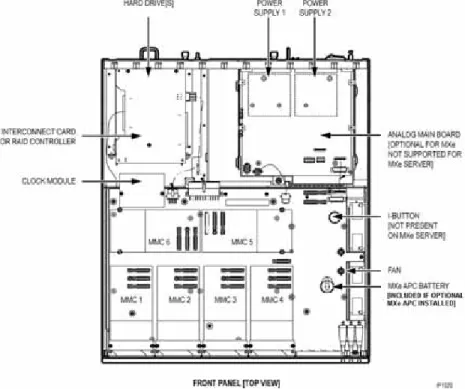
The following illustrations include available components for each controller. Refer to Chapter 6 on page 157 for installation instructions.
Figure 5: Slot Locations for the MXe Controller and MXe Server Card Table 4: MXe Controller: Supported Modules
Module MMC1 MMC2 MMC3 MMC4 MMC5 MMC6
FIM Yes Yes Yes Yes No No
T1/E1 Yes Yes Yes Yes No No
BRI Yes Yes Yes Yes No No
CIM Yes Yes Yes Yes No No
DSP Yes Yes Yes Yes Yes Yes
DSP II No No No Yes Yes Yes
Echo Canceller Yes Yes Yes Yes Yes Yes
Table 5: MXe Server: Supported Modules
Module MMC1 MMC2 MMC3 MMC4 MMC5 MMC6
DSP Up to two DSP modules for additional compression
DSP II No No No Yes Yes Yes
Echo Canceller Yes Yes Yes Yes Yes Yes
Figure 6: Slot Locations on the AX Controller Card Table 4: MXe Controller: Supported Modules (continued)
Module MMC1 MMC2 MMC3 MMC4 MMC5 MMC6
Figure 7: Slot Locations for the CXi Controller (with an Ethernet L2 Switch)
Note: Only three ASU ports are supported system wide.
Figure 8: Slot Locations for the CX Controller (without an Ethernet L2 Switch)
Note: Only three ASU ports are supported system-wide.
Figure 9: Slot Locations for the CXi II Controller (with an Ethernet L2 Switch with POE)
Figure 10: Slot Locations for the CX II Controller (without an Ethernet L2 Switch)
Identify Controller Component Options
Table 6: Controller Component and Upgrade Options
Processor Speed 2 G 450 450 533 266 450
Components MXe7
Server AX6 MXe II3 MXe III13
CX/CXi CX/CXi II2 LX
Embedded CIM — — —
Quad CIM (page 172) —
FIM (page 170) — — DSP (page 170) Echo canceller (page 170) — T1/E1 Framer (page 171) — — BRI Framer (page 171) — T1/E1 Combo (page 171) —
Line Cards (AX, ASU II) (page 231) — — — — — AMB (MXe) (page 175) — — — — AMB (CX/CXi) (page 176) — — — — —
AMB (CX II/CXi II) (page 178) — — — — — AOB (CX/CXi) (page 179) — — — — — AOB (CX/CXi) (page 180) — — — — — Redundant Power Supply (page 222) — — Page 1 of 3
Hard Drives (page 205) — RAID controller (page 223) — — — Redundant Hard Drives Mxe II/MXe Server (page 210)
— — — —
Redundant Hard Drives Mxe III (page 215) — — — — — Stratum 3 Clock (page 173) — 12 —8 8 —8 System ID Module (page 174) — — — — — System i-Button (page 174) — — System Flash (page 233) — — — — —
Voice Mail Flash (page 233) — — — — — E2T (page 202) — — — Application Processor Card9 (APC-CX(i)) (page 188) — — — — — APC-CX(i) II10 (page 194) — — — — — Application Processor Card (APC-MXe) — — — — — Upgrading to a 1400-User System — — — —
Table 6: Controller Component and Upgrade Options (continued)
Processor Speed 2 G 450 450 533 266 450
Components MXe7
Server AX6 MXe II3 MXe III13
CX/CXi CX/CXi II2 LX
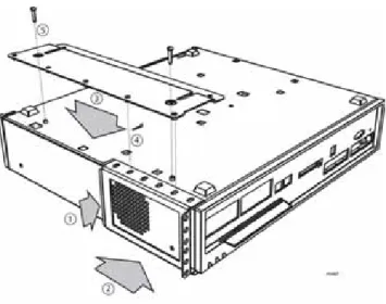
Remove Controller Cover
To remove the controller cover:
1. Power down the controller (see page 129).
2. Disconnect all cables.
3. Remove cover as shown in Figure 11 or Figure 12.
Notes:
1. The Quad CIM requires Release 7.1 or later software. The CIM ports on the MXe Server are not available for use, but the LEDs will continue to flash. 2. The CX/CXi require Release 6.0 or later software. The CX II/CXi II require MCD 4.0 or later software.
3. The MXe II requires Release 7.0 or later software. 4. Requires the installation of a second processor, the E2T. 5. The embedded CIM is not an option and is not field replaceable. 6. The AX requires Release 7.1 or later software.
7. The MXe Server requires Release 8.0 or later software.
8. The CX II, CXi II and AX controllers use an embedded Stratum 3 Clock, so it is not field replaceable.
9. The APC-CX(i) is available for the CX or CXi running Rel 7.1+ software. 10. The APC-CX(i) II is available for the CX II or CXi II running MCD 4.0+ software.
11. The Hard Drive 2 pack for the MXe Server comes with one of the hard drives loaded with the Communications Director software and the other one blank. Mirror the blank drive before using the Software Installer. See page 211. 12. The MXe Server does not have any digital trunks, so it does not use a Stratum 3 clock.
13. The MXe III requires MCD Release 4.2 or later software.
Table 6: Controller Component and Upgrade Options (continued)
Processor Speed 2 G 450 450 533 266 450
Components MXe7
Server AX6 MXe II3 MXe III13
CX/CXi CX/CXi II2 LX
Figure 12: MXe/MXe Server - Removing the Cover
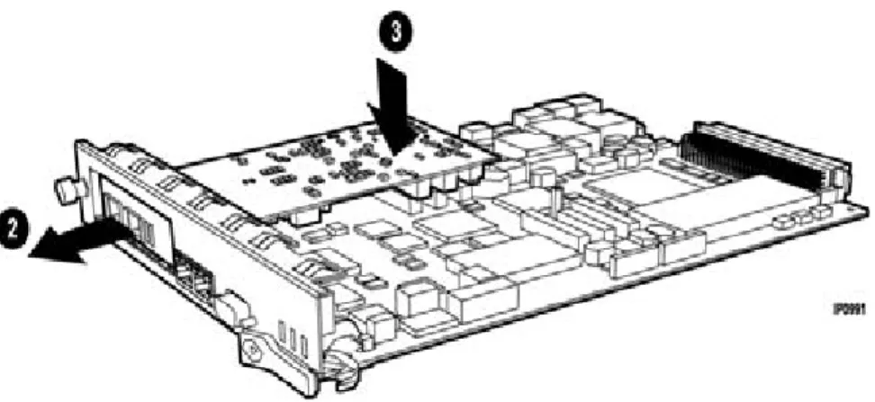
Install Controller Modules
Read the Safety Instructions before performing the procedures in this chapter (see “Safety Instructions” on page 3).
Figure 11: CX/CXi, CX II/CXi II - Removing the cover
Tip:Before installing a 3300 ICP, always read the RN for the software you are installing (see “3300 ICP Documentation - Mitel eDocs” on page 8).
1. Shut down the controller (see page 129).
2. Disconnect all cables from the controller.
3. Remove the controller cover (page 47).
4. Remove the module from its packaging.
MXe, MXe Server, CX/CXi, CX II/CXi II
5. Remove the blank module cover at the front of the controller, and insert the module in an appropriate slot.
6. If you are replacing a defective module, remove the screws and lock washers and pull up on the module to remove it.
7. Secure the module to the controller using the screws and pillars provided with the module.
8. Tighten the controller faceplate screw nearest the MMC slot.
9. Replace the controller cover or the controller card.
10. Reconnect the cables to the controller.
11. Power up the controller.
AX
1. Remove the blanking plate (or the old MMC) from the controller by removing the screws that hold the standoffs to the controller. (The screws are on the back side of the controller card.)
2. Back off the controller faceplate screw nearest the MMC slot a couple of turns (because the screw interferes with the removal/insertion of T1/E1, Quad BRI, Quad CIM, or Dual FIM).
3. Slide the blanking plate out of the opening from the back of the controller faceplate.
4. Remove the two standoffs (closest to the face plate) from the blanking plate (or old MMC). Retain the standoffs and screws.
5. Fasten the standoffs to the front of the new MMC.
CAUTION: Proceed with extreme care to avoid damaging com-ponents on the controller card.
6. Carefully slide the MMC face plate under the lip of the controller face plate. See Figure 13. Do not push the MMC past the controller face plate as shown in Figure 14.
7. Re-install and/or re-tighten the screws.
8. Continue with procedure as described in the specific FRU instructions.
Figure 13: Position module at an angle (AX)