Lincoln Laboratory
MASSACHUSETTS INSTITUTE OF TECHNOLOGYLEXINGTON, MASSACHUSETTS ESC-TR-2006-082
Project Report
ATC-334
Guidance Material for Mode S-Specific
Protocol Application Avionics
R.D. Grappel
R.T. Wiken
4 June 2007
Prepared for the Department of the Air Force under Contract FA8721-05-0002.
This document is disseminated under the sponsorship of the Department
of Transportation in the interest of information exchange. The United
REPORT DOCUMENTATION PAGE
OMB No. 0704-0188 Form ApprovedPublic reporting burden for this collection of information is estimated to average 1 hour per response, including the time for reviewing instructions, searching existing data sources, gathering and maintaining the data needed, and completing and reviewing this collection of information. Send comments regarding this burden estimate or any other aspect of this collection of information, including suggestions for reducing this burden to Department of Defense, Washington Headquarters Services, Directorate for Information Operations and Reports (0704-0188), 1215 Jefferson Davis Highway, Suite 1204, Arlington, VA 22202-4302. Respondents should be aware that notwithstanding any other provision of law, no person shall be subject to any penalty for failing to comply with a collection of information if it does not display a currently valid OMB control number. PLEASE DO NOT RETURN YOUR FORM TO THE ABOVE ADDRESS.
1. REPORT DATE
4 June 2007
2. REPORT TYPE
Project Report
3. DATES COVERED (From - To)
4. TITLE AND SUBTITLE 5a. CONTRACT NUMBER
FA8721-05-C-0002 Guidance Material for Mode S-Specific Protocol Application Avionics 5b. GRANT NUMBER
5c. PROGRAM ELEMENT NUMBER
6. AUTHOR(S) 5d. PROJECT NUMBER
1564
Robert D. Grappel and Randall T. Wiken 5e. TASK NUMBER
1
5f. WORK UNIT NUMBER 7. PERFORMING ORGANIZATION NAME(S) AND ADDRESS(ES)
AND ADDRESS(ES)
8. PERFORMING ORGANIZATION REPORT NUMBER
MIT Lincoln Laboratory 244 Wood Street
Lexington, MA 02420-9108
PR-ATC-334
9. SPONSORING / MONITORING AGENCY NAME(S) AND ADDRESS(ES) 10. SPONSOR/MONITOR’S ACRONYM(S)
Department of the Air Force, ESC
5 Eglin Street 11. SPONSOR/MONITOR’S REPORT
Hanscom AFB, MA 01731 NUMBER(S)
ESC-TR-2006-082
12. DISTRIBUTION / AVAILABILITY STATEMENT
Approved for public release; distribution is unlimited.
13. SUPPLEMENTARY NOTES
14. ABSTRACT
This ATC report presents guidance material for the use of the “Ground-Initiated Comm. B” (GICB) register set contained in a Mode S transponder. The guidance material is intended to provide assistance for implementers of Mode S avionics installations. A common summary of the requirements and specifications for Mode S GICB transponder register data link applications is developed. While this ATC report focuses primarily on the “Elementary Surveillance” (ELS), “Enhanced Surveillance” (EHS), and “Automatic Dependent
Surveillance–Broadcast” (ADS-B) applications, guidance information is also provided for general transponder configuration and architecture of other Mode S functions employing the GICB register set.
Although the information contained in this ATC report is drawn from a number of approved national and international standards, it is not intended to replace or supersede those standards documents. In the event of a conflict or contradiction between this ATC report and any approved standards (see references 1 through 6), the approved standard takes precedence and the reader is encouraged to contact the authors of this document. Reference 4 is the most-recent and complete specification for the Mode S register contents. For ease of reference, the relevant Mode S register images have been duplicated in Appendix A of this ATC report.
Unclassified
Guidance Material for Mode S-Specific Protocol Application Avionics
R.D. Grappel R.T. Wiken
Group 42
4 June 2007
Massachusetts Institute of Technology
Lincoln Laboratory
Project Report ATC-334
Lexington
Massachusetts
EXECUTIVE SUMMARY
This ATC report discusses the three main applications of the Mode S-Specific Protocols (MSP) that are currently being fitted to aircraft and ground systems worldwide and are being considered for future military and civilian functions. It also seeks to provide a common summary of the requirements and specifications for the Mode S avionics employed in these applications. The three MSP applications described in this ATC report are:
ELS Elementary Surveillance; EHS Enhanced Surveillance; and
ADS-B Automatic Dependent Surveillance Broadcast ADS-B (implemented in Mode S as 1090 MHz “Extended Squitter” (ES)).
Elementary Surveillance
ELS support is required by the European Mode S mandate. Support of ELS consists primarily of populating and maintaining four Mode S transponder registers:
1016 Data Link Capability Report;
1716 Common-Usage Ground-Initiated Comm B (GICB) Capability Report; 2016 Aircraft Identification Register; and
3016 Airborne Collision Avoidance System (ACAS) Resolution Advisory (RA).
The first two of these registers form the basis for the transponder configuration, register extraction, and fault-detection protocols used by all MSP applications. There are several other registers used to configure a Mode S transponder for varying levels of data link applications, but the two basic transponder registers (1016 and 1716) are sufficient for the application set described in this ATC report. The later two of the ELS-required transponder registers provide the aircraft flight identification (2016) and information about the state of the onboard ACAS equipment (3016). The definition, specification, and content of the ELS application data is well defined and quite mature.
It should be noted that the European ELS mandate also includes the requirement to support the Mode S Surveillance Identifier (SI) code protocol. The SI protocol provides for additional interrogator codes and therefore supports a higher level of overlapping coverage by multiple Mode S ground sensors. This is seen as an immediate need in European airspace. The only impact of the use of SI codes discussed in this ATC report is the setting of the SI bit in the Data Link Capability Report (register 1016).
iv Enhanced Surveillance
EHS support is required by the European Mode S mandate. Support of EHS consists of populating and maintaining three Mode S transponder registers beyond those required for ELS:
4016 Selected Vertical Intention; 5016 Track and Turn Report; and 6016 Heading and Speed Report.
These Mode S registers are intended to support improved ATC systems where knowledge of the aircraft’s intended flight path can be used to supplement surveillance tracking. The data fields in these registers are simply a reformatting of values expected to already exist in the aircraft on its ARINC 429 data buses or equivalent information from data buses on aircraft not equipped with ARINC buses. The register definitions provide a status bit for each data field. A particular avionics suite may provide a subset of the data available from its onboard flight management system or other avionics. Register 4016 is the most complex of the EHS register set, since it uses a wide variety of data sources. Different aircraft configurations (e.g., Boeing versus Airbus) may need to set the data fields in this register differently, depending on the particular data sources and pilot control inputs available in the particular avionics.
It should be noted that the definition of the contents of register 4016 has been redefined from an earlier version that sought to provide 3-dimensional intent information in a single register. The current register 4016 definition has been limited to vertical intent only as this is the data with the most immediate ATC application.
Automatic Dependent Surveillance – Broadcast
The specification of the Mode S ADS-B (1090 MHz Extended Squitter) application is by far the most complex of the MSP applications described in this ATC report; its description occupies nearly half the pages. One reason for this complexity is simply the number of registers defined for this application. There are six “basic” 1090 MHz ES ADS-B registers (five more “event-driven” ADS-B registers will be discussed later):
0516 ES Airborne Position; 0616 ES Surface Position; 0716 ES Status;
0816 ES Identification and Type; 0916 ES Airborne Velocity; and 0A16 ES Event-Driven Information.
Note that the 1090 MHz ES ADS-B application separates position from velocity data in the airborne case. This is done because there are not enough bits in a given Mode S transponder register to fully encode both position and velocity in three dimensions. A separate register is defined for the surface case that incorporates both position and velocity fields. The ADS-B “aircraft identification and type” register (0816) parallels the aircraft identification register (2016) defined for the ELS application. The rationale for this apparent duplication of data is that ELS registers are extracted through an interrogation by an external Mode S interrogator, while ADS-B registers are spontaneously broadcast (squittered). No interrogation is required to receive the ADS-B data. In addition, register (0816) also contains aircraft type information that is not contained in register (2016).
A second reason for the complexity of the Mode S ADS-B definition is that two different versions of the specification are currently being maintained. The original specification (termed “Version 0”) is given in Radio Technical Commission for Aeronautics (RTCA) DO-260 originally published in 2000. A newer specification (termed “Version 1”) is given in RTCA DO-260A originally published in 2003. The Version 1 formats are fully compatible with the Version 0 formats, in that a receiver built to either standard can correctly receive and process ADS-B messages generated by transmitting equipment built to either standard. Version 1 differs from Version 0 in two areas: (a) its specification of the ADS-B “event-driven” transponder register set, and (b) how available avionics surveillance accuracy is specified.
The five Mode S 1090 MHz ES ADS-B “event-driven” transponder registers extend the basic set of broadcast data to include slowly changing values or rare events that need not be continuously broadcast. As was the case for aircraft identification, this broadcast mechanism parallels the operation of other Mode S transponder registers whose contents are obtained by interrogation/extraction. The 1090 MHz ES ADS-B “event-driven” register set is:
6116 ES Emergency Priority Status;
6216 Current Trajectory Change Point in Version 0, reserved for target state and status information in Version 1;
6316 Next Trajectory Change Point in Version 0, not used in Version 1;
6416 Aircraft Operational Coordination Message in Version 0, not used in Version 1; and 6516 ES Aircraft Operational Status.
The ES Emergency Priority Status data in register 6116 parallels that in ELS register 3016, and the aircraft’s emergency state may also be obtained via direct Mode S surveillance. The data in registers 6216 and 6316 was defined to provide long-term aircraft intent information for potential conflict detection and resolution algorithms to be supported via 1090 ES. Again, this data is equivalent to that defined in other registers whose contents may be obtained via direct Mode S interrogation/extraction. Support for registers 6216 and 6316 was removed from the Version 1 definition of 1090 MHz ES ADS-B. Register 6416 was envisaged to support various “paired” aircraft applications (formation flying). It is also no longer
vi
supported in Version 1. The definition of register 6516 has been greatly expanded in Version 1 to support various potential airborne and surface operations.
As was indicated above, there are a number of registers and data fields defined for the 1090 MHz ES ADS-B application that parallel data available elsewhere in the Mode S transponder registers. The 1090 ES ADS-B broadcast (squitter) protocol is seen by its designers to operate independently from applications employing Mode S interrogation/extraction (e.g., ELS and EHS). Also, it is seen that the set of 1090 ES ADS-B supported applications is quite fluid and undergoing change. The requirements for support of ADS-B applications beyond the “basic” set (position, velocity, and identification) are not yet completely firm.
Also, the Version 0 and Version 1 definitions of 1090 MHz ES ADS-B differ in how the available avionics surveillance accuracy is specified. Version 0 avionics use a “navigation uncertainty category” (NUC), while Version 1 avionics provide a “navigation accuracy category” (NAC), a “navigational integrity category” (NIC), and a “surveillance integrity level” (SIL). Version 1 also re-defines the usage and contents of the “event-driven” register set.
ELS/EHS/ADS-B Summary
In summary, the Mode S ELS and EHS applications as required by the European mandate are mature and stable. Equipping for these Mode S applications is relatively straightforward. The source of data for the ELS and EHS registers is largely the aircraft’s ARINC-429 buses or equivalent information from data buses on aircraft not equipped with ARINC buses. The task of populating the required Mode S registers is primarily a reformatting process.
The case of the Mode S 1090 MHz ES ADS-B application is somewhat different from the ELS and EHS applications. The 1090 MHz ES ADS-B application is more complex than ELS and EHS. This additional complexity arises from several areas:
• The 1090 MHz ADS-B application requires more Mode S transponder register definitions than ELS and EHS;
• There are two application specification versions for 1090 MHz ES ADS-B; and
• The data formatting and control protocols required for 1090 MHz ES ADS-B are more complex than those used in ELS and EHS.
There is no current equipage mandate for 1090 MHz ES ADS-B systems. There is a prototype ADS-B implementation in Alaska (project Capstone) using the Universal Access Transceiver (UAT). An operational ADS-B surveillance system using 1090 MHz ES exclusively (conforming to the specification in [6]) is currently being installed in Australia. Some air-to-air usage of 1090 MHz ES messages to augment TCAS is also underway. The operational concepts for ADS-B applications are less stable than those for ELS and EHS, and these operational concepts are likely to evolve as they mature.
PREFACE
This ATC report is the result of research and development sponsored by the United States Air Force (USAF) 853rd Electronic Systems Group at Hanscom Air Force Base, MA. The authors have prepared this report to assist the USAF in the task of equipping their aircraft with appropriate Mode S avionics to support the European mandate for “Elementary Surveillance” (ELS) and “Enhanced Surveillance” (EHS) applications.
The authors wish to acknowledge the many writers and reviewers who prepared references 1 through 6, from which this ATC report derives much of its material. The authors would like to thank the reviewers who provided many significant comments and corrections on drafts of this ATC report, with special thanks to Bill Thedford, Eric Potier, Mikael Ponnau, Bob Saffell, Dieter Kunze, Richard Bush, Vincent Orlando, Ann Drumm, Val Heinz, and Garrett Harris. Finally, the authors acknowledge the input from the “European Organisation for Civil Aviation Equipment” (EUROCAE) “Mode S Enhanced Surveillance” Working Group 49 who provided valuable comments on this text.
TABLE OF CONTENTS
Executive Summary iii
Preface vii
List of Illustrations XI
List of Tables xi
1. INTRODUCTION 1
2. AVIONICS CONFIGURATION SETTINGS 3
2.1 Mode S-Specific Services GICB Capability Reports (Regs. 1816...1C16) 3
2.2 Mode S-Specific Services MSP Capability Reports (Regs. 1D16..1F16) 4
2.3 Common Usage GICB Capability Report (Reg. 1716) 4
2.4 Data Link Capability Report (Reg. 1016) 5
2.5 Transponder and ACAS Type/Part Number/Software Revision
(Regs. E316, E416, E516, E616) 7
3. CONFIGURATION AND FAILURE PROTOCOLS 9
4. ELEMENTARY SURVEILLANCE (ELS) TRANSPONDER REGISTERS 11
4.1 Aircraft Identification (Reg. 2016) 11
4.2 ACAS Resolution Advisory (Reg. 3016) 11
5. ENHANCED SURVEILLANCE (EHS) TRANSPONDER REGISTERS 15
5.1 Selected Vertical Intention (Reg. 4016) 15
5.2 Track and Turn Report (Reg. 5016) 17
5.3 Heading and Speed Report (Reg. 6016) 18
5.4 Quasi-Static Parameter Monitoring (Reg. 5F16) 18
6. 1090 EXTENDED SQUITTER (MODE S ADS-B) 21
6.1 Mode S Extended Squitter Airborne Position (Reg. 0516) 23
x
TABLE OF CONTENTS (CONTINUED)
6.4 Extended Squitter Aircraft Identification and Category (Reg. 0816) 26
6.5 Mode S Extended Squitter Airborne Velocity (Reg. 0916) 27
6.5.1 Cartesian (Ground Speed) Encoding 29
6.5.2 Polar (Heading and Airspeed) Encoding 29
6.6 Mode S Extended Squitter Event-Driven Information (Reg. 0A16) 29
6.6.1 Emergency/ACAS RA (Reg. 6116) 30
6.6.2 Aircraft Operational Status Message (Reg. 6516) 31
6.7 Version 1 Mode S ADS-B Squitter Changes 32
6.7.1 Version 1 ADS-B Format Type Encoding 32
6.7.2 Version 1 NAC Encoding for Velocity 34
6.7.3 Version 1 Format for Aircraft Operational Status (Reg. 6516) 35
6.7.4 Proposed Version 1 Format for Target State and Status Information (Reg. 6216) 42
7. MILITARY SURVEILLANCE APPLICATIONS 45
7.1 Military Register F116 45
7.2 Military Register F216 45
APPENDIX A. MODE S REGISTER LAYOUTS FROM ICAO DOC 9871 47
LIST OF ACRONYMS 85
LIST OF ILLUSTRATIONS
Figure
No. Page
1-1 Mode S Register Assignments for ELS, EHS, and ADS-B 2
LIST OF TABLES
Table
No. Page
2-1 Register Configuration Bit Assignments in Mode S-Specific Services GICB
Capability Reports 3
2-2 ACAS Configuration Bits in Data Link Capability Register (1016) 6
2-3 Version Number Coding in the Mode S Data Link Capability Register (1016) 7 4-1 Field Definitions for ACAS Resolution Advisory Transponder Register (3016) 12 4-2 Bit Definitions in RAC Field of ACAS Resolution Advisory Register (3016) 12 4-3 TTI Coding Definitions for the ACAS Resolution Advisory Register (3016) 13 4-4 TID Field Coding of the ACAS Resolution Advisory Register when TTI=2 13
4-5 Internal Coding of ARA Field when ARA Bit 1=1 14
4-6 Internal Coding of ARA Field when ARA Bit 1=0 and MTI=1 14
5-1 Coding for the Altitude Source Field in the Selected Vertical Intent (Reg. 4016) 16
5-2 Data Subfields in the Track and Turn Report (Reg. 5016) 17
5-3 Data Subfields in the Heading and Speed Report (Reg. 6016) 18
5-4 Data Subfields in the Quasi-Static Parameter Monitoring Register (5F16) 19
6-1 Mode S Extended Squitter Format Type Codes (Version 0) 22
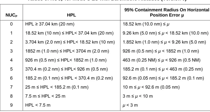
6-2 Values of NUCP for Mode S ES with Barometric Altitudes (Version 0) 23 6-3 Mode S Extended Squitter Airborne Position Surveillance Status Field Coding 24
6-4 Surface Squitter Rate Encodings for the Extended Squitter Status Register 0716 26
6-5 Vehicle Category Coding Values in the Extended Squitter Register 0816 27
xii
LIST OF TABLES (CONTINUED)
Table
No. Page
6-8 Event-Driven Protocol GICB Registers and Type Codes 30
6-9 Register 6116 Emergency Code Definitions 31
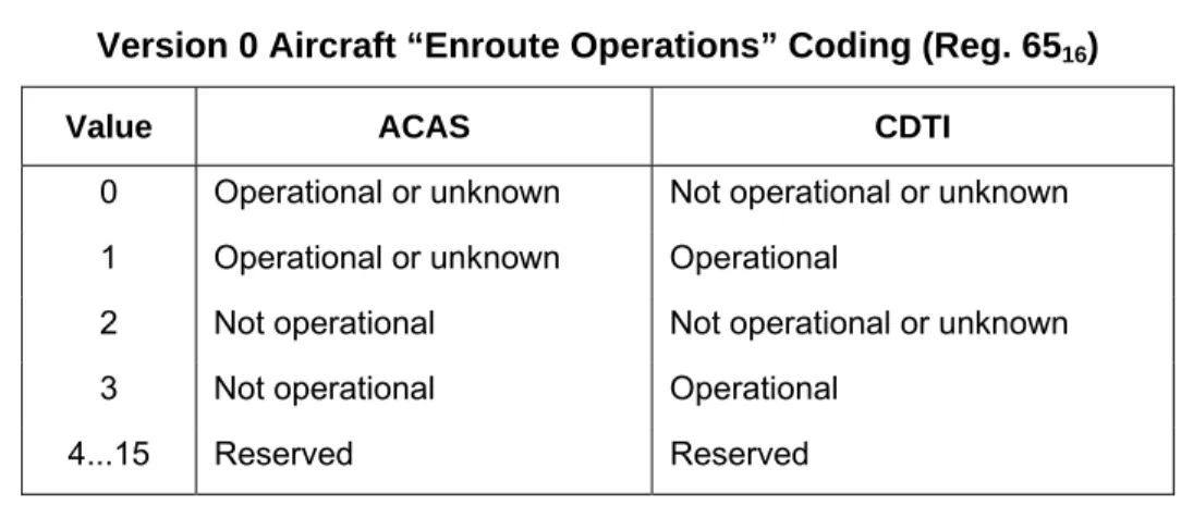
6-10 Version 0 Aircraft “Enroute Operations” Coding (Reg. 6516) 32
6-11 Mode S Extended Squitter Format Type Codes (Version 1) 33
6-12 Values of NIC for Mode S Extended Squitter (Version 1) 34
6-13 Values of NACV For Airborne Velocity Register 0916 (Version 1) 35
6-14 Version 1 Aircraft Operational Status Format (Reg. 6516) 35
6-15 Version 1 Airborne Capability Classfor Aircraft Operational Status (Reg. 6516) 36 6-16 Version 1 Surface Capability Classfor Aircraft Operational Status (Reg. 6516) 37 6-17 Version 1 Surface Length/Width Encodingfor Aircraft Operational Status (Reg. 6516) 38
6-18 Version 1 Operational Mode Encodingfor Aircraft Operational Status (Reg. 6516) 39 6-19 Version 1 Aircraft Operational Status NACP Encodingfor Aircraft Operational
Status (Reg. 6516) 40
6-20 Version 1 Aircraft Operational Status SIL Encoding for Aircraft Operational
Status (Reg. 6516) 41
6-21 Mapping Version 0 Format Type Coding to Version 1 NIC and SIL Values 41 6-22 Version 1 Target State and Status Vertical Data Available/Source Encodings
(Reg. 6216) 42
6-23 Version 1 Target State and Status Target Altitude Capability Encodings
(Reg. 6216) 43
6-24 Version 1 Target State and Status Target Vertical Mode Indicator Encodings
(Reg. 6216) 43
6-25 Version 1 Target State and Status Target Horizontal Mode Indicator Encodings
(Reg. 6216) 44
7-1 DF=19 Applications Field (AF) Values 45
A-1 ICAO DOC 9871 Table A-2-5: BDS code 0,5 – Extended squitter airborne position 48 A-2(0) ICAO DOC 9871 Table A-2-6. BDS code 0,6 – Extended squitter surface position
(Version 0) 49
A-2(1) ICAO DOC 9871 Table A-2-6. BDS code 0,6 – Extended squitter surface position
(Version 1) 50
LIST OF TABLES (CONTINUED)
Table
No. Page
A-4(0) ICAO DOC 9871 Table A-2-8. BDS code 0,8 – Extended squitter aircraft
identification and category (Version 0) 52
A-4(1) ICAO DOC 9871 Table A-2-8. BDS code 0,8 – Extended squitter aircraft
identification and category (Version 1) 53
A-5(0) ICAO DOC 9871 Table A-2-9a. BDS code 0,9 – Extended squitter airborne
velocity (Subtypes 1 and 2: Velocity over ground) (Version 0) 54 A-5(1) ICAO DOC 9871 Table A-2-9a. BDS code 0,9 – Extended squitter airborne
velocity (Subtypes 1 and 2: Velocity over ground) (Version 1) 55 A-6(0) ICAO DOC 9871 Table A-2-9b. BDS code 0,9 – Extended squitter airborne
velocity (Subtypes 3 and 4: Airspeed and heading)(Version 0) 56 A-6(1) ICAO DOC 9871 Table A-2-9b. BDS code 0,9 – Extended squitter airborne
velocity (Subtypes 3 and 4: Airspeed and heading)(Version 1) 57 A-7 ICAO DOC 9871 Table A-2-16. BDS code 1,0 – Data link capability report 58 A-8 ICAO DOC 9871 Table A-2-16. BDS code 1,0 – Data link capability report
(Concluded) 59
A-9 ICAO DOC 9871 Table A-2-23. BDS code 1,7 – Common usage GICB capability
report 60
A-10 ICAO DOC 9871 Table A-2-24 . BDS code 1,8 – Mode S specific services
GICB capability report (1 of 5) 61
A-11 ICAO DOC 9871 Table A-2-25. BDS code 1,9 – Mode S specific services GICB
capability report (2 of 5) 62
A-12 ICAO DOC 9871 Table A-2-26. BDS code 1,A – Mode S specific services GICB
capability report (3 of 5) 63
A-13 ICAO DOC 9871 Table A-2-27. BDS code 1,B – Mode S specific services GICB
capability report (4 of 5) 64
A-14 ICAO DOC 9871 Table A-2-28. BDS code 1,C – Mode S specific services GICB
capability report (5 of 5) 65
A-15 ICAO DOC 9871 Table A-2-32. BDS code 2,0 – Aircraft identification 66 A-16 ICAO DOC 9871 Table A-2-48. BDS code 3,0 – ACAS active resolution advisory 67 A-17 ICAO DOC 9871 Table A-2-64. BDS code 4,0 – Selected vertical intention 68 A-18 ICAO DOC 9871 Table A-2-80. BDS code 5,0 – Track and turn report 69
xiv
LIST OF TABLES (CONTINUED)
Table
No. Page
A-20 ICAO DOC 9871 Table A-2-96. BDS code 6,0 – Heading and speed report 71 A-21(0) ICAO DOC 9871 Table A-2-97. BDS code 6,1 – Extended squitter emergency/
priority status (Version 0) 72
A-21(1a) ICAO DOC 9871 Table A-2-97. BDS code 6,1 – Extended squitter emergency/
priority status (Version 1a) 73
A-21(1b) ICAO DOC 9871 Table A-2-97. BDS code 6,1 – Extended squitter emergency/
priority status (Version 1b) 74
A-22 ICAO DOC 9871 Table D-2-98. BDS Code 6,2 – Target state and status information 75 A-23(0) ICAO DOC 9871 Table A-2-101. BDS code 6,5 – Extended squitter aircraft
operational status (Version 0) 76
A-23(1) ICAO DOC 9871 Table A-2-101. BDS code 6,5 – Extended squitter aircraft
operational status (Version 1) 77
A-24 ICAO DOC 9871 Table A-2-227. BDS code E,3 – Transponder type / part number 78 A-25 ICAO DOC 9871 Table A-2-228. BDS code E,4 – Transponder software revision
number 79
A-26 ICAO DOC 9871 Table A-2-229. BDS code E,5 – ACAS unit part number 80 A-27 ICAO DOC 9871 Table A-2-230. BDS code E,6 – ACAS unit software revision 81 A-28 ICAO DOC 9871 Table A-2-241. BDS code F,1 – Military applications 82 A-29 ICAO DOC 9871 Table A-2-242. BDS code F,2 – Military applications 83
1.
INTRODUCTION
This ATC report presents guidance material for the use of the “Ground-Initiated Comm. B” (GICB) transponder register set within a Mode S avionics installation. The intent of this ATC report is to reduce the effect of complexity in various implementations of Mode S transponder applications resulting from the number of documentation sources and revisions that have occurred over time. This ATC report combines information from several sources, including references 1 through 6) into a single and organized entity. It focuses on the “Elementary Surveillance” (ELS), “Enhanced Surveillance” (EHS), and “Automatic Dependent Surveillance–Broadcast” (ADS-B, also called 1090 MHz Extended Squitter when implemented in Mode S) applications, as well as support of military surveillance functions. The information in this ATC report will also help in the development of other Mode S data link applications.
Section 2 of this ATC report discusses the configuration settings in the aircraft Mode S transponder and avionics required to support Mode S data link applications such as ELS, EHS, and ADS-B. Section 3 goes on to describe the protocols employed by Mode S data link applications to determine the avionics configuration and to deal with changes in configuration due to equipment failures. Section 4 describes the additional Mode S transponder register support required for the ELS application. Section 5 describes the additional registers required for the EHS application. Section 6 describes the additional registers and associated protocols required for the Mode S 1090 MHz Extended Squitter (ADS-B) application. Finally, Section 7 describes the additional registers used to support military surveillance applications.
Although the information provided in this ATC report is drawn from several approved national and international standards, it is not intended to replace or supersede those standards. Rather, this report is meant to provide guidance for system implementers. In the event of a conflict or contradiction between this document and any approved standards (see references 1 through 6), the approved standards take precedence and the reader is encouraged to contact the authors of this report. Reference 4 is the most-recent and complete specification for the Mode S register contents. For ease of reference, the relevant Mode S register images have been duplicated in Appendix A of this document.
Note: This document contains many references to Mode S transponder registers. Following international documentation standards, they are listed as hexadecimal numbers. In this document, register numbers are stated as hexadecimal values (subscript 16). (Note: Some international standards use a comma-notation to represent hexadecimal transponder register numbers without requiring subscripts.) Also, there are many references to ARINC 429 labels, which are expressed herein in octal (subscript 8).
Figure 1-1 illustrates the organization and basic data flows for the subset of the registers used in the ELS, EHS, ADS-B, and military applications.
2
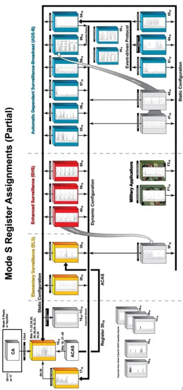
Figure 1-1. Mode S Register Assignments for ELS, EHS, and ADS-B.
Figure 1-1 illustrates the organization and basic data flows for the subset of the registers used in the ELS, EHS, ADS-B, and military applications. Color-coding is used to group the registers by application: ELS (yellow), EHS (red), ADS-B (blue), and military (green). Registers shown in gray are indirectly involved with these applications, but are not directly called out by the application specification. The figure employs thick arrows to denote the transponder static and dynamic configuration data flows and the ADS-B event-driven protocol.
2.
AVIONICS CONFIGURATION SETTINGS
This section describes the various registers used to specify the configuration of the Mode S avionics with respect to the various Mode S applications (e.g., ELS, EHS, and ADS-B) that might be installed on the aircraft. Two sets of these registers (the Mode S-Specific services GICB capability reports and the “Mode S-Specific Protocol” [MSP] capability reports) are static and simply indicate the airborne configuration. Two other configuration registers (the common usage GICB capability report and the data link capability report) combine static configuration information with dynamic status information on the timeliness of data within certain other registers. Combined with the “configuration and failure protocols” described in Section 3 below, these registers allow the sensor extracting data from the transponder to ascertain which data values are valid in the transponder’s registers.
2.1 MODE S-SPECIFIC SERVICES GICB CAPABILITY REPORTS (REGS. 1816...1C16)
Registers 1816 though 1C16 are used to specify which of the 255 possible registers are actually implemented in the particular avionics configuration. (Register number zero is reserved.) Note that these capability bits indicate only that the avionics are configured to be able to load the indicated register – these bits do not indicate whether the register is, in fact, being loaded in a timely manner. The indication of timely data is performed for “important” register applications via the “common usage capability report” register 1716 (see Section 2.3 below). If there is no bit assigned in register 1716 for the particular register of interest, then a status bit (or bits) within the particular register itself must to be tested to determine if the register is being loaded appropriately.
The installed capability for registers is indicated by setting the appropriate bit corresponding to the given register in the GICB Capability Report register as indicated in Table 2-1. The bit position numbering for each register capability bit starts with the least significant bit (LSB, bit 56) of each register. The 25 most-significant bits in register 1C16 are not used.
TABLE 2-1
Register Configuration Bit Assignments in Mode S-Specific Services GICB Capability Reports
First GICB Last GICB Capability Register
0116 3816 1816 3916 7016 1916 7116 A816 1A16 A916 E016 1B16
4
2.2 MODE S-SPECIFIC SERVICES MSP CAPABILITY REPORTS (REGS. 1D16..1F16)
Registers 1D16 through 1F16 contain bits that indicate which (if any) of the 63 uplink and the 63 downlink MSP channels are supported by the particular avionics installation. (Note: These functions are not required for the support of ELS, EHS, or ADS-B 1090 Squitter). Example MSP functions include the “Traffic Information Service” [TIS uplink channel 2] and ACAS sensitivity control [uplink channel 5].) The bits in the Mode S-Specific services MSP capability report registers simply indicate the avionics configuration, not whether the particular MSP functions are currently operational.
Within each of the Mode S-Specific services MSP capability reports, the high-order 28 bits of each register are used to specify the configuration state of uplink MSP channels, while the low-order 28 bits of each register are used to indicate the configuration state of the corresponding downlink MSP channels. Register 1D16 indicates the configuration status of MSP channels 1 through 28 (uplink and downlink). Register 1E16 indicates the configuration status of MSP channels 29 through 56. Register 1F16 indicates the configuration status of MSP channels 57 through 63. The remaining bits in register 1F16 are unused. 2.3 COMMON USAGE GICB CAPABILITY REPORT (REG. 1716)
Register 1716 contains a series of bit flags that indicate the status of a subset of the Mode S transponder’s registers expected to be the most likely to be implemented. All of the registers involved with the ELS, EHS, and ADS-B applications of Mode S have bit flags assigned in this register. These bit flags partly parallel the similar bit flags in the Mode S-Specific Services GICB Capability Reports – they cannot be set unless the avionics configuration supports the particular register. Providing a single capability register for all the “commonly used” registers allows a sensor to obtain all the configuration information it needs for a given aircraft with a single GICB register extraction – instead of having to pick bits from multiple registers in the range 1816 through 1C16 for each register that is of interest to the sensor. Unlike the bit flags in the Mode S-Specific Services GICB Capability Report registers, the bit flags in the “common usage” GICB capability report are not a static indication of whether the particular register is installed in the aircraft’s avionics. Rather, the bit flags in register 1716 are dynamic – if set, they indicate that the particular register has been updated in a timely manner and contains valid data. All registers having bit flags in register 1716 are continually monitored at a rate consistent with the update rate required for the individual register. The bit flag is set to ‘1’ by the transponder only if valid data is being input to that register at the required rate.
The bit flag in register 1716 for a given register is set to '1' if at least one data field in that register is receiving valid data at the required rate. The data field status bits in the given register itself indicate which of the data items in the register are current and valid. Each of the EHS registers contain several data items, therefore to ensure compliance with the European mandates it is important to verify that each field status bit is set, and then verify that the bits in each of the data fields are set to some non-zero value. For completeness, a final check should compare the values in those data fields with an independent surveillance source, such as radar, to verify that the values are correctly reporting the aircraft's state.
There is a bit in the “data link capability report” (see Section 2.4 below) combined with an avionics protocol (see Section 3.0 below) that is used to signal changes in the contents of register 1716 (indicating loss or recovery of timely data in one or more registers being supported in the avionics). The sensor will, in absence of avionics failures, only have to extract the contents of register 1716 once.
2.4 DATA LINK CAPABILITY REPORT (REG. 1016)
The Data Link Capability Report (Reg. 1016) is the root source of configuration and operational status information for the Mode S avionics system. Register 1016 contains subfields that describe the capabilities and operational status of the Mode S transponder itself, its support for Mode S data link applications (e.g., ACAS, ADS-B, etc.) and its support for the Mode S sub network of the Aeronautical Telecommunications Network (ATN). This section discusses primarily those subfields of the Data Link Capability Report register that are pertinent to the ELS, EHS, and ADS-B applications. See [3] and [4] for a complete definition of the contents of this register.
The first eight bits of register 1016 contain the fixed value “1016” – used to identify the Data Link Capability Report when it is broadcast via the air-initiated Comm-B protocol. A Mode S transponder broadcasts the contents of register 1016 whenever its contents change (indicating some sort of change and/or failure or recovery mode in the Mode S avionics). Bit 24 of register 1016 is used to indicate whether the Mode S transponder can support the “enhanced protocol” of Mode S – the ability to perform extended length message (ELM) transactions with more than one sensor simultaneously. Bit 35 of register 1016 is used to indicate whether the Mode S transponder can support the “surveillance identifier” (SI) code extension to the Mode S link protocols. Bits 26 through 28 of register 1016 are used to indicate the rate at which the Mode S transponder can perform uplink ELM transactions. Bits 29 through 32 of register 1016 are used to indicate the rate at which the Mode S transponder can perform downlink ELM transactions. All of these static configuration settings are functions of the Mode S transponder capabilities. (Note: The ELS, EHS, and ADS-B Mode S data link applications of Mode S do not employ ELM transactions [either uplink or downlink] or the “enhanced protocol.”)
Bit 25 of register 1016 is used to indicate whether the Mode S avionics are configured with any Mode S-Specific service applications. These applications include extraction of any registers excepting 0216 through 0416, 1016, 1716 through 1C16, 2016, and 3016. They also include any MSP applications as discussed in Section 2.2 above. This is a static bit indicating the avionics configuration.
Bit 33 of register 1016 is used to indicate whether the Mode S avionics are configured to support the extraction of aircraft identification (Reg. 2016). If this bit is set statically, it mirrors bit 25 of register 1816. However, it is preferable to set this bit dynamically to mirror bit 7 of register 1716 (which indicates that the aircraft identification is currently valid). Section 4.1 describes the contents of register 2016.
Bit 34 of register 1016 is used to indicate whether the Mode S avionics are configured to support ADS-B squitter applications. Bit 34 is set if both the airborne and surface position registers (0516 and 0616) have been updated within the last ten seconds. Hence, the setting of bit 34 is dynamic and equivalent to the “and” of bits 1 and 2 of register 1716 (bits 1 and 2 indicate the configuration of registers 0516 and 0616 respectively). Section 6 describes the ADS-B squitter register contents.
Bit 36 of register 1016 is used to indicate whether the contents of the common usage capability register 1716 (see Section 2.3 above) have changed. Such a change indicates some sort of failure or
6
discussion of the protocols for extracting and monitoring the configuration and failure status of an aircraft’s Mode S avionics is given in Section 3.0 below.
Bits 16 and 37 through 40 of register 1016 are used as bit flags to indicate the status of an ACAS application that might be installed as part of the aircraft’s Mode S avionics. Table 2-2 defines the use of these ACAS bit flags.
TABLE 2-2
ACAS Configuration Bits in Data Link Capability Register (1016)
Bit No. Usage
16 0 Î ACAS failed or in standby 1 Î ACAS operational
37 0 Î ACAS II
1 Î ACAS III (reserved) 38 0 Î ACAS generating TAs only
1 Î ACAS generating TAs and RAs 39 0 Î no ACAS onboard
1 Î ACAS onboard
40 Reserved for ACAS
Bits 17 through 23 of register 1016 are used to denote the documentation version of International Civil Aviation Organization (ICAO) standards [3] and [4] used to encode the register contents in the aircraft’s Mode S avionics. The register definitions must be consistent with one document version, although only a subset of the documents’ features need be installed. The version number should be set to a non-zero value if any Mode S-Specific services are used in the avionics (i.e., if bit 25 of register 1016 is set). Table 2-3 defines the coding of the version number field.
Bits 41 through 56 of register 1016 are used to indicate the support status of each of the 16 “Data Terminal Equipment” (DTE) sub-addresses in the Mode S subnetwork of the “Aeronautical Telecommunications Network (ATN). This functionality is not used by any of the currently defined Mode S applications (i.e., ELS, EHS, ADS-B).
TABLE 2-3
Version Number Coding in the Mode S Data Link Capability Register (1016)
Coding
Year of Annex 10 Amendment [3]
Edition of ICAO Doc 9871 [4]
0 Mode S subnetwork not available
1 1996 Not applicable
2 1998 Not applicable
3 2002 Not applicable
4 2007 Edition 1
5...127 Unassigned
2.5 TRANSPONDER AND ACAS TYPE / PART NUMBER / SOFTWARE REVISION (REGS. E316, E416, E516, E616)
The recent issue of the Mode S GICB register formats [4] includes a set of four registers that are used to specify the type and software revision of the Mode S transponder and ACAS unit (if any) on board the aircraft. Registers E316 and E416 refer to the transponder itself, while registers E516 and E616 refer to the ACAS unit. The first register of each pair refers to the part number or type specification of the equipment, while the second register of each pair refers to the software revision hosted in the equipment. (Note: for operational reasons, some military installations may not populate these registers.)
The format of all four registers is the same. The first bit in the register format is a status flag that indicates the validity of the data in the register. The next two bits in the register form a format type code value. The format type code value ‘0’ indicates that the remainder of the register uses the “part number” (P/N) format – a decimal digit string. The format type code value ‘1’ indicates that the remainder of the register uses the Mode S character format. Type codes ‘2’ and ‘3’ are reserved.
If the format of the register is P/N, then the part number is expressed as a string of up to 12 “binary-coded decimal” (BCD) digits. This is the recommended format for the expression of these registers. If the part number (revision number) is not available, then the first eight characters of the commercial name are encoded in the register using the Mode S character string format. As described in Section 4.1 below (and in [1]), the Mode S character format uses 6 bits for each character. Letters ‘A’ through ‘Z’ are encoded using values 1 through 26. Digits ‘0’ through ‘9’ are encoded using values 48 through 57. The space character is encoded as value 32. All other encoding values are undefined. For either P/N or character format, the last five bits of the register format are reserved.
3.
CONFIGURATION AND FAILURE PROTOCOLS
The first processing step for any Mode S data link application is to obtain the transponder capability (CA) value from the aircraft. The 3-bit CA field is found in the “Mode S All-Call Reply and Acquisition Squitter” (DF=11) and the “Extended Squitter” (DF=17) downlinks. If CA=0, then this transponder is surveillance-only and supports no data link functions at all. If CA=1, 2, or 3, then this transponder is using an earlier form of the Mode S protocol. These Mode S transponders support only GICB extraction of the aircraft’s data link capability (Reg. 1016), aircraft identity (Reg. 2016), ACAS RA (Reg. 3016), and air-initiated Comm B broadcast. Values of CA greater than or equal to 4 indicate that the Mode S transponder is fully capable of at least 56-bit short uplink and downlink message transfer. These Mode S transponders can support the ELS, EHS, ADS-B, and other data link functions (given that their avionics load the appropriate registers, etc.). The Mode S transponder CA value should be stored in the data link application as part of the aircraft “state.” (See [1] for a full description of the transponder capability values.)
Given that the Mode S transponder’s CA value is 4 or greater, the second processing step for any Mode S data link application is to extract the transponder’s Mode S data link capability report (Reg. 1016) as described in Section 2.4 above. The contents of this register should be stored in the data link application as part of the aircraft “state.” Bits in this register indicate the support of such Mode S data link functions as aircraft identification, ADS-B, ACAS, etc. The Mode S-Specific services capability bit indicates whether the avionics installation supports further data link functions. If this bit is set, the Mode S data link application would next extract the common-usage capability register (1716) as described in Section 2.3 above. The contents of this register would also be stored as part of the aircraft “state.”
The processing protocol described in this section so far is sufficient initialization for basic data link applications such as ELS, EHS, and ADS-B, since all their status and configuration information is available from registers 1016 and 1716. Other Mode S data link applications (e.g., Traffic Information Service [TIS]) might need to extract one or more of the Mode S-Specific services GICB capability reports (see Section 2.1 above) or one or more of the Mode S-Specific services MSP capability reports (see Section 2.2 above) to determine whether the aircraft’s avionics support the particular Mode S data link application. The additional capability register contents also become part of the aircraft “state” in the application.
This completes the initialization processing for Mode S data link applications. The application should subsequently monitor any air-initiated Comm B broadcast messages received from the particular aircraft in order to detect any changes in the aircraft’s configuration status. Any changes in the contents of any of the registers 1016, 2016, or 3016 triggers a downlink message via the air-initiated Comm B broadcast protocol including the updated register contents. The Mode S data link application should update the aircraft’s “state” values with the new ones. The changed state might result in discontinuance (or reinstatement) of certain Mode S data link functions. A change in the value of the common-usage GICB
4.
ELEMENTARY SURVEILLANCE (ELS) TRANSPONDER REGISTERS
The “Elementary Surveillance” application (ELS) includes registers 1016, and 1716, and1816 through 1C16 as discussed in Sections 2 and 3 above. In addition, ELS includes the “aircraft identification” register (2016) and the “ACAS resolution advisory” register (3016) for aircraft equipped with ACAS. This section provides guidance on the contents and operation of registers 2016 and 3016.
4.1 AIRCRAFT IDENTIFICATION (REG. 2016)
The intent of this register is to provide a means for applications to correlate surveillance data (containing the Mode S address and the Mode 3/A code) with the flight plan (containing the aircraft identification). The aircraft identification register contains an 8-character text string that is to be set equal to the flight plan identification (if one is available) – otherwise, it should be set to the aircraft’s registration marking. The text string should be left justified in the register. No intervening “space” codes should be included in the text string. Any unused characters at the end of the text string should be set to the “space” code.
A 6-bit character encoding is employed which incorporates upper-case letters, decimal digits, and a space character. The encoding is described in [1] and [4]. Letters ‘A’ through ‘Z’ are encoded using values 1 through 26. Digits ‘0’ through ‘9’ are encoded using values 48 through 57. The space character is encoded as value 32. All other encoding values are undefined. The input text string could come from ARINC words 233-2368 (Flight Identification), 301-3038 (Aircraft Identification), or 3608 (Flight Number).
Note that receiving applications will detect any changes in or loss of the contents of this register via an air-initiated Comm B broadcast message from the Mode S transponder. This broadcast downlink message occurs within 2 seconds of the change in or loss of the data in GICB register 2016.
4.2 ACAS RESOLUTION ADVISORY (REG. 3016)
The format of the ACAS Resolution Advisory Register content is defined in [3] and [4]. This register allows external systems (such as a ground Mode S sensor) to extract the current state of an ACAS system’s resolution advisory display(s). The structure of the ACAS resolution advisory’s 56 bits is illustrated in Table 4-1.
12
TABLE 4-1
Field Definitions for ACAS Resolution Advisory Transponder Register (3016) Field Name Number of Bits
BDS 8 ARA 14 RAC 4 RAT 1 MTI 1 TTI 2 TID 26
The “Comm-B Data Selector” (BDS) field is set to 3016 to denote the ACAS resolution advisory when this data is broadcast. (An air-initiated Comm B broadcast downlink is generated whenever the register contents change.) The “Active RAs” (ARA) field indicates the characteristics of the RA (if any) generated by ACAS. The coding of the ARA field is described below. The “RAs Active” (RAC) field is composed of four bit flags indicating the current state of active RA complements received by ACAS from other aircraft. The RAC field coding is shown in Table 4-2.
TABLE 4-2
Bit Definitions in RAC Field of ACAS Resolution Advisory Register (3016) Bit in RAC Field Meaning if Set
1 Do not pass below
2 Do not pass above
3 Do not turn left 4 Do not turn right
The “RA terminated” (RAT) bit is cleared (set to “0”) if the ACAS RA in the ARA field is active. The RAT bit is set to “1” to indicate that the RA has been terminated. The “multiple threat indicator” (MTI) bit is set to “1” if two or more simultaneous threats are being processed by the ACAS. The MTI bit is cleared when there is a single threat or if there is no current threat, depending on the coding of the high-order bit of the ARA field. The “threat type indicator” (TTI) field defines the type of data in the “threat identity data” (TID) field that follows it. The coding of the TTI field is described in Table 4-3.
TABLE 4-3
TTI Coding Definitions for the ACAS Resolution Advisory Register (3016)
TTI Coding Meaning
0 No identity data in TID 1 TID contains Mode S address
2 TID contains altitude, range, and bearing
3 Not assigned
If the TTI field value is ‘1,’ the TID field contains the 24-bit Mode S address of the threat (when the threat is Mode S equipped). The low-order 2 bits of the TID field are cleared. If the TTI field value is ‘2,’ the TID field is subdivided into three subfields as illustrated in Table 4-4. Note: If there are multiple threats, the TID field contains data for the most-recently declared threat.
TABLE 4-4
TID Field Coding of the ACAS Resolution Advisory Register when TTI=2
TID Subfield Number of Bits Coding
Altitude 13 Mode C altitude code of threat. Bit ordering is C1 A1 C2 A2 C4 A4 0 B1 D1 B2 D2 B4 D4
Range 7 0 Î no range estimate available
1 Î range < 0.05 Nmi.
2…126 Î (range – 1) / 10 Nmi. 127 Î range > 12.55 Nmi.
Bearing 6 0 Î no bearing estimate available
1...60 Î bearing in 6 degree increments 61...63 Î not assigned
The ARA field is a set of bit flags that can take on two sets of defined values, depending on the value of its high-order bit and the value of the separate MTI bit field. If the high-order bit of the ARA field is cleared, this indicates that there is more than one threat and the RA is intended to provide separation below some and above others (if MTI=1), or no RA has been generated (if MTI=0). If the high-order bit of the ARA field is set, this indicates that there is only one threat or the RA is intended to provide separation in the same direction for all the threats. The internal definitions for the remaining bit flags in the ARA field (when ARA bit 1=1) are illustrated in Tables 4-5 and 4-6.
14
TABLE 4-5
Internal Coding of ARA Field When ARA Bit 1=1
Bit Number in ARA
Nield Definition (when ARA bit 1=1)
2 0 Î RA is preventive 1 Î RA is corrective
3 0 Î upward sense RA
1 Î downward sense RA 4 0 Î not increased rate
1 Î increased rate
5 0 Î RA is not a sense reversal 1 Î RA is a sense reversal 6 0 Î not altitude crossing
1 Î altitude crossing
7 0 Î RA is vertical speed limit 1 ÎRA is positive
8...14 Reserved for ACAS III
The internal definitions for the remaining bit flags in the ARA field (when ARA bit 1=0 and MTI=1) are illustrated in the Table 4-6.
TABLE 4-6
Internal Coding of ARA Field When ARA Bit 1=0 and MTI=1
Bit Number in
ARA Field Definition (when ARA bit 1=0 and MTI=1)
2 0 Î RA does not require upward correction 1 Î RA requires upward correction
3 0 Î RA does not require positive climb 1 Î RA requires positive climb
4 0 Î RA does not require downward correction 1 Î RA requires downward correction
5 0 Î RA does not require positive descent 1 Î RA requires positive descent
6 0 Î RA does not require altitude crossing 1 Î RA requires altitude crossing
7 0 Î RA is not a sense reversal 1 ÎRA is a sense reversal 8...14 Reserved for ACAS III
5.
ENHANCED SURVEILLANCE (EHS) TRANSPONDER REGISTERS
This section discusses the three registers (4016, 5016, and 6016) that make up the “Enhanced Surveillance” (EHS) function. (See reference 4 for the complete definition of these registers.) Whenever possible, the data value entered into the register should come from the sources in actual control of the aircraft. If the value of any data parameter received from the avionics data source exceeds the allowable range for the particular register format, the maximum allowable data value (with the appropriate sign) is encoded in the register. The least-significant bit for each encoded data value should be obtained via rounding. If any data value is not available in the aircraft’s avionics, then all bits in the register value for that data should be cleared.
Within this section, the ARINC 429 word that provides the required data value is given in the accompanying tables. In some cases there is a choice of applicable ARINC 429 words for a data value – there may be a choice of ARINC 429 formats (binary or BCD), etc. Note: Alternative data bus standards such as IEEE 1553B (used by some military aircraft) have equivalent mechanisms to transfer the required information. The details of the data transfer may vary from aircraft to aircraft.
In addition to the EHS registers (4016, 5016, and 6016), an additional register is used to provide Mode S applications a means to monitor changes in flight parameters that do not change frequently in normal flight (i.e., are expected to stay constant for 5 minutes or more at a time). An application can determine whether one or more of these flight parameters has changed by a single extraction of the “quasi-static parameter monitoring” register 5F16.
5.1 SELECTED VERTICAL INTENTION (REG. 4016)
The selected vertical intention report (Reg. 4016) contains five data subfields, each incorporating their own independent status bit. The maximum acceptable update interval for any of the data subfields in this transponder register is 1 second. In general, if data updates are missing for a time no longer than twice the specified maximum update interval or 2 seconds (whichever is greater), then the status bit for this data item (if specified for the given field) must indicate that the data is invalid and the subfield in the register itself should be filled with zeroes. The update interval for each data subfield in the register should be sufficient to ensure that the maximum latency of each data value is not exceeded. (Note: If all five of the status fields in the register are simultaneously cleared, then the register itself is no longer valid. Its corresponding bit in the Mode S common usage capability register [1716] should be cleared.)
The purpose of the data in register 4016 is to provide access to information about the aircraft’s intentions with respect to altitude changes during flight. This information could improve the effectiveness of conflict-probe applications and could provide an aid to air-traffic controllers in maintaining vertical separation among aircraft.
16
The first data subfield in register 4016 is the selected MCP/FCU Selected Altitude. This is the value that the flight crew have dialed into the autopilot flight control unit / mode control panel or altitude alerter, and is, if the autopilot is engaged and a number of other conditions are met, the altitude at which the aircraft will resume level flight (or has already leveled off) at the completion of the current maneuvers. The source of this data is the aircraft’s Mode Control Panel (MCP) or Flight Control Unit (FCU). The selected altitude field supports a “read-back” function so that ground surveillance applications can determine what the pilot has loaded into the aircraft’s altitude control avionics. Note that changes in the MCP/FCU Selected Altitude are reflected in a change to bits 1 and 2 of the Quasi-Static Parameter Monitor (Reg. 5F16) described in Section 5.4 below.
The second data subfield in this register is the FMS selected altitude from the aircraft’s Flight Management System (FMS). In ARINC avionics architectures, these data may be obtained from ARINC 429 label 102 (binary) or 025 (BCD).
The third data subfield in this register is the barometric pressure setting minus 800 millibars. This data value may be obtained from ARINC 429 label 2348.
The fourth data subfield in this register is a set of four bit flags that indicate the Mode Status of the MCP/FCU. The first bit (bit 48) is the status bit used to indicate whether altitude mode information is being actively provided. The second bit is set to indicate VNAV mode (e.g., ARINC 429 label 2728), the third bit is set to indicate APPROACH mode (e.g., ARINC 429 label 2738), and the fourth bit is set to indicate ALT HOLD mode (e.g., ARINC 429 label 2728). Note that changes in the Mode Status are reflected in a change to bits 17 and 18 of the Quasi-Static Parameter Monitor (Reg. 5F16) described in Section 5.4 below. Also, if there is no means in the avionics to determine the altitude mode, bits 48 through 51 should be cleared to zero.
The fifth data subfield (bits 54-56) in this register specifies which of the first two data fields in this register or the current aircraft altitude should be used to determine the short-term intent value at which the aircraft will level off. The status bit for this field (bit 54) indicates whether such altitude mode information is currently provided. Table 5-1 describes the coding for the 2-bit target altitude source value (bits 55-56). Note: if the aircraft’s avionics are not able to determine the source of target altitude data (see [4] for the appropriate avionics logic), then the source field is to be cleared as well as its respective status bit. Also, note that changes in the FMS Selected Altitude are reflected in a change to bits 23 and 24 of the Quasi-Static Parameter Monitor (Reg. 5F16) described in Section 5.4 below.
TABLE 5-1
Coding for the Altitude Source Field in the Selected Vertical Intent (Reg. 4016) Target Altitude Source
Coding (Bits 55-56) Description
0 Unknown
1 Aircraft altitude
2 FCU/MCP selected altitude
5.2 TRACK AND TURN REPORT (REG. 5016)
The Track and Turn Report (Reg. 5016) contains five data subfields, each incorporating their own independent status bit. The purpose of this register is to aid conflict probe and long-term air traffic control functions in maintaining accurate aircraft horizontal track positions and velocities. The maximum acceptable update interval for any of the data subfields in this transponder register is 1 second. In general, if data updates are missing for a time no longer than twice the specified maximum update interval or 2 seconds (whichever is greater), then the status bit for this data item (if specified for the given field) must indicate that the data is invalid and the subfield in the register itself should be filled with zeroes. The update interval for each data subfield in the register should be sufficient to ensure that the maximum latency of each data value is not exceeded. Note: If all of the five status fields in the register are simultaneously cleared, then the register itself is no longer valid. Its corresponding bit in the common usage capability register (Reg. 1716) should be cleared – which triggers a change in the data link capability register (Reg. 1016) and a downlink message is then sent via the air-initiated Comm B broadcast protocol. Table 5-2 lists the data subfields in register 5016.
TABLE 5-2
Data Subfields in the Track and Turn Report (Reg. 5016)
Data Field LSB Range ARINC 429 Word (octal)
Roll angle 45/256 degrees –90...90 degrees 325
True Track angle 90/512 degrees –180...180 degrees 313 (binary) 013 (BCD)
103 (GNSS1 – binary)
Ground Speed 2 knots 0...2046 knots 312 (binary)
012 (BCD)
112 (GNSS – binary) Track Angle Rate 1/32 degree/second –16...16 degree/second 335 (see note below)
True Airspeed 2 knots 0...2046 knots 210 (binary)
230 (BCD)
Note: For ARINC General Aviation Manufacturers Association (GAMA) avionics configurations, ARINC 429 label 3358 is not used for the true track angle rate but for another parameter. For this particular ARINC configuration, the true track angle rate field in the Track and Turn Register should be cleared. Applications could infer the track angle rate from the true airspeed and roll angle values.
18 5.3 HEADING AND SPEED REPORT (REG. 6016)
The Heading and Speed Report (Reg. 6016) contains five data subfields, each incorporating its own independent status bit. The purpose of this register (like register 5016 described in Section 5.2 above) is to aid conflict probe and long-term air traffic control functions in maintaining accurate aircraft horizontal track positions and velocities. The maximum acceptable update interval for any of the data subfields in this transponder register is 1 second. In general, if data updates are missing for a time no longer than twice the specified maximum update interval or 2 seconds (whichever is greater), then the status bit for this data item (if specified for the given field) must indicate that the data is invalid and the field in the register itself should be filled with zeroes. The update interval for each data subfield in the register should be sufficient to ensure that the maximum latency of each data value is not exceeded. Note: if all the five status fields in the register are simultaneously cleared, then the register itself is no longer valid. Its corresponding bit in the common usage capability register (1716) should be cleared – which triggers a change in the data link capability register (1016) and a broadcast message with the new contents of register 1016 via the air-initiated Comm B downlink protocol. Table 5-3 lists the data subfields in register 6016.
TABLE 5-3
Data Subfields in the Heading and Speed Report (Reg. 6016)
Data Value LSB Range ARINC 429 Word (octal)
Magnetic Heading 90/512 degrees –180...180 degrees
320 (binary) 014 (BCD)
Indicated Airspeed 1 knot 0...1023 knots 206 (computed airspeed)
Mach 0.004 Mach 0...4.09 Mach 205
Barometric Altitude Rate 32 feet/minute –6,384...16,352 feet/minute
212 Inertial Vertical Velocity 32 feet/minute –6,384...16,352
feet/minute
365
5.4 QUASI-STATIC PARAMETER MONITORING (REG. 5F16)
The “Quasi-Static Parameter Monitoring” register is provided to permit monitoring of changes in parameters that do not normally change very frequently (those expected to be stable for 5 minutes or more) by extracting a single register. This register contains 28 two-bit subfields that indicate whether their respective flight parameter has changed its value. A subfield value of 00 binary indicates that there is no valid data available for the particular monitored parameter. If valid data is available for the particular monitored parameter, then the subfield value cycles through binary values 01, 10, and 11 each time there is a change in the monitored parameter. A change in any of the subfields in the quasi-static parameter monitoring register (5F16) triggers a change in bit 23 of the common usage capability register (1716) – which, in turn, triggers a change in the data link capability register (1016) and a downlink broadcast message with the new contents of register 1016 via the air-initiated Comm B protocol. Table 5-4 lists the
data subfields in register 5F16 and the register that contains the parameter being monitored by that data field. Note that some of the monitored parameters (e.g., those which used to indicate horizontal intent) do not currently have defined register locations. Some of this is due to changes in the register assignments over time. These subfields in register 5F16 are reserved for future parameter monitoring applications.
TABLE 5-4
Data Subfields in the Quasi-Static Parameter Monitoring Register (5F16) Bits in
Register 5F16 Monitored Parameter
Register(s) Containing Parameter
1,2 MCP/FCU Selected Altitude 4016
3,4 Reserved (was Selected Heading) —
5,6 Reserved (was Selected Speed) —
7,8 Reserved (was Selected Mach Number) —
9,10 Reserved (was Selected Altitude Rate) —
11,12 Reserved (was Selected Flight Path Angle) —
13,14 Next Waypoint 4116, 4216, 4316
15,16 Reserved (was FMS Horizontal Mode) —
17,18 FMS Vertical Mode 4016
19,20 VHF Channel Report 4816
21,22 Meteorological Hazards 4516
23,24 FMS Selected Altitude 4016
25,26 Barometric Pressure (minus 800 mb) 4016
6.
1090 EXTENDED SQUITTER (MODE S ADS-B)
This section discusses the registers and protocols used for Mode S Extended Squitter applications. A “squitter” is a spontaneous broadcast transmission by the Mode S transponder on the 1090 MHz frequency not initiated by an interrogation on 1030 MHz. Mode S support of “automatic dependent surveillance–broadcast” (ADS-B) is provided by means of squitters. Registers 0516 through 0A16 (plus 6116 to 6516) are used by the extended squitter protocols. Note that registers 0516 through 0A16 have a matching capability bit in the common-usage capability register 1716 (see Section 2.3 above). See references [4], [5], and [6] for the complete definition of the Mode S ADS-B application.
There are two defined standards for Mode S extended squitter applications. The initial standard [5] is termed “Version 0.” Using these message formats, ADS-B surveillance quality is reported in terms of the “Navigation Uncertainty Category” (NUC), which can be an indication of either the accuracy or the integrity of the navigation data used by ADS-B. However, there is no indication provided as to whether the NUC value is based on integrity or accuracy.
The revised ADS-B standard [6] is termed “Version 1.” The Version 1 formats overcome the limits of Version 0 by reporting separately the “Navigation Accuracy Category” (NAC), the “Navigation Integrity Category” (NIC), and the “Surveillance Integrity Level” (SIL). The Version 1 formats are fully compatible with the Version 0 formats, in that a receiver built to either standard can correctly receive and process ADS-B messages generated by transmitting equipment built to either standard. Sections 6.1 through 6.6 of this paper cover Version 0 formats, indicating where Version 1 formats differ. Section 6.7 of this paper covers the Version 1-specific format revisions. Note: Reference 4 covers both Version 0 and Version 1.
There are 32 types of Mode S extended squitter messages denoted by a 5-bit format type code. Each squitter message begins with the 5-bit format type code. Table 6-1 describes the various format type codes, their related squitter formats, and the section in this paper that discusses the particular squitter type. (The “navigational uncertainty category in position” [NUCP] is defined in [4] and [5]. It is a measure of the integrity and accuracy of the navigational data available from the aircraft’s avionics, both horizontally and vertically.) Note that Version 0 ADS-B uses NUC, while Version 1 formats use NIC, NAC, and SIL. See Section 6.7.1 of this paper for the format type coding used in Version 1.
22
TABLE 6-1
Mode S Extended Squitter Format Type Codes (Version 0)
Format
Type Code Description Altitude Type
Section
Reference NUCP
0 No position information Barometric or none 6.1 0
1 Identification (Category D) N.A. 6.4 --
2 Identification (Category C) N.A. 6.4 --
3 Identification (Category B) N.A. 6.4 --
4 Identification (Category A) N.A. 6.4 --
5 Surface Position N.A. 6.2 9
6 Surface Position N.A. 6.2 8
7 Surface Position N.A. 6.2 7
8 Surface Position N.A. 6.2 6
9 Airborne Position Barometric 6.1 9
10 Airborne Position Barometric 6.1 8
11 Airborne Position Barometric 6.1 7
12 Airborne Position Barometric 6.1 6
13 Airborne Position Barometric 6.1 5
14 Airborne Position Barometric 6.1 4
15 Airborne Position Barometric 6.1 3
16 Airborne Position Barometric 6.1 2
17 Airborne Position Barometric 6.1 1
18 Airborne Position Barometric 6.1 0
19 Airborne Velocity Either 6.5 --
20 Airborne Position GNSS 6.1 9
21 Airborne Position GNSS 6.1 8
22 Airborne Position GNSS 6.1 Reserved
23 Reserved for testing
24 Reserved for surface system status
25 Reserved 26 Reserved 27 Reserved
28 Extended Squitter Aircraft Status 6.6.1 —
29 Was Current/Next Trajectory Change Point in Version 0 [5] – proposed re-definition for Target State and Status [4]
6.6.2 6.7.4
—
30 Aircraft Operational Coordination in Version 0 [5], no longer used in Version 1 [6]
6.6.3 —