April 2013
GEOTECHNICAL INVESTIGATION
Lot 126, Murphy Street
Report Number. 137632049-001-R-Rev0
Distribution:
1 Copy - Charles Wright Architects Pty Ltd
Submitted to:
Lindsay & Robyn Partridge
c/- Charles Wright Architects Pty Ltd PO Box 492
LOT 126, MURPHY STREET
April 2013
Report No. 137632049-001-R-Rev0 i
Table of Contents
1.0 INTRODUCTION ... 2 2.0 REGIONAL GEOLOGY ... 2 3.0 FIELDWORK ... 2 3.1 Methods ... 2 3.2 Site Overview ... 3 3.3 Subsurface Conditions ... 3 4.0 LABORATORY TESTING ... 3 5.0 ENGINEERING COMMENTS ... 4 5.1 Stability ... 4 5.2 Drainage ... 55.3 Site Preparation and Earthworks ... 5
5.4 Footings and Site Classification ... 6
5.4.1 Shallow Footings ... 6 5.4.2 Deep Footings ... 6 5.4.3 Site Classification ... 7 5.5 Uncontrolled Fill ... 7 5.6 Retaining Walls ... 7 6.0 LIMITATIONS ... 8 FIGURES
Figure 1 : Test Pit Locations Plan Figure 2: Cross Section A
APPENDIX A
Results of Field Investigation
APPENDIX B
Laboratory Test Results
APPENDIX C
Results of Stability Analysis
APPENDIX D
LOT 126, MURPHY STREET
April 2013
Report No. 137632049-001-R-Rev0 2
1.0
INTRODUCTION
At the request of Charles Wright Architects (CWA), Golder Associates (Golder) has undertaken a geotechnical investigation for a proposed residence at Lot 126 Murphy Street, Port Douglas. The investigation has been conducted in general accordance with our proposal (Golder Reference P37632116-001-P-Rev0) dated 13 March 2013.
The aim of the investigation was to assess geotechnical and groundwater conditions at the site of the proposed development and to provide the following information:
Subsurface conditions at the site;
Stability of the slopes following proposed development and comments on slope stabilisation, if necessary;
To assess the risk of upslope hazards, including the potential for rockfall and debris flows; Comments on foundation options and provide geotechnical design parameters;
To provide a site classification as per AS2870.
This report presents the results of the geotechnical investigation together with preliminary geotechnical input related to the items outlined above. As final details related to the proposed foundation types and structural loads are not known at this time, all geotechnical comments provided in this report should be considered preliminary in nature and should be reviewed and, if necessary, revised once the final design details are available. This report is based on drawings provided to Golder by CWA and geotechnical investigation and laboratory testing undertaken by Golder.
2.0
REGIONAL GEOLOGY
The Queensland Department of Natural Resources and Mines 1:250 000 Geological Map Mossman, Sheet SE 55-1, indicates that the site is underlain by the late Silurian / Devonian Hodgkinson Formation dominated by arenite rich conglomerates.
Subsurface conditions encountered in the test pits are considered to be consistent with the materials indicated on the geological map.
3.0
FIELDWORK
3.1
Methods
The field investigation was carried out on 19March 2013 under the full time supervision of a geotechnical engineer from Golder. The fieldwork consisted:
Site walkover of the site;
Excavation of two test pits (TP1 and TP2) to a maximum depth of 3.0 m. Observation and logging of two cuttings where the soil / rock profile is exposed;
Performance of a Dynamic Cone Penetrometer (DCP) test adjacent to each of the test pits.
The approximate test pit locations are indicated on Figure 1. Ground surface levels were interpolated from contour information presented on the RPS Contour and Detail Surveying drawing (115859-1) dated 26 November 2012 provided by CWA.
LOT 126, MURPHY STREET
April 2013
Report No. 137632049-001-R-Rev0 3
3.2
Site Overview
The site is sloping to the southwest at approximately 25 degrees. Its currently undeveloped and is predominately covered by dense rainforest vegetation. A level platform near the centre of the Lot is situated between an old rock retaining wall and a low cut batter where weathered bedrock is exposed. Disused concrete steps are located north of the platform, and an open concrete drain runs along the northeast lot boundary. A second low cutting exposing weathered bedrock is located at the south corner of the Lot near the end of the concrete driveway. Site drainage is toward the west corner.
3.3
Subsurface Conditions
General sub soil conditions comprise localised uncontrolled fill overlying natural topsoil, colluvium and weathered bedrock. The fill deposits are associated with the level bench near the centre of the Lot, with minor deposits noted along the western property boundary. The colluvium thickens toward the southwest portion of the Lot. The thickness of colluvium and residual soils was noted to a depth of 2.9 m below ground level in Test Pit 1 before grading to low strength rock The approximate limits of the uncontrolled fill and the thickened colluvium are illustrated on Figures 1 and 2. Detailed descriptions of the subsurface conditions are presented in Appendix A.
The conditions encountered were generally as follows:
GL to 0.4/1.9m Topsoil: very loose to loose silty Sand.
1.9 to 2.9 m Colluvium / Residual soil: very dense silty clayey Sand.
Deeper than 0.4/2.9 Extremely weathered to highly weathered rock (phyilite), extremely low to low and low to medium strength
Groundwater was not encountered in the test pits to the depths advanced at the time of investigation. It should be noted that groundwater levels may fluctuate seasonally and during heavy rainfall periods.
4.0
LABORATORY TESTING
Laboratory plasticity and particle distribution tests were carried out on samples of the soils encountered to confirm field classifications. Laboratory test result sheets are presented in Appendix B and are summarised in Table 1 below.
Table 1: Summary of Laboratory Testing
ID Depth (m) Material Emerson Class Number Grading (%) Plasticity (%)
Gravel Sand Fines LL PI
TP1 0.6-0.9 Silty CLAY 8 7 43 50 41 8
TP1 1.3-1.6 Silty CLAY 5 8 42 50 31 6
Due to the nature of the materials encountered on site, undisturbed samples for shrink/swell testing could not be recovered.
LOT 126, MURPHY STREET
April 2013
Report No. 137632049-001-R-Rev0 4
5.0
ENGINEERING COMMENTS
5.1
Stability
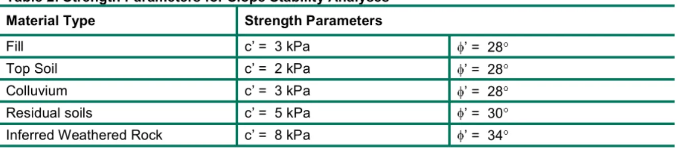
Stability analyses were carried out for the site profile indicated on Figure 2 for the existing slope profile. Based on judgement and previous experience with similar materials, the following strength parameters were adopted for the stability analyses:
Table 2: Strength Parameters for Slope Stability Analyses
Material Type Strength Parameters
Fill c = 3 kPa = 28
Top Soil c = 2 kPa = 28
Colluvium c = 3 kPa = 28
Residual soils c = 5 kPa = 30
Inferred Weathered Rock c = 8 kPa = 34
Analyses were performed for what were considered to be dry or normal conditions and for what were considered to be wet or extreme conditions. A pore water pressure co-efficient, Ru= 0.2 was used to
simulate seepage/water infiltration for extreme conditions within the soils and Ru= 0.1 within weathered
rock zones respectively. The analyses were carried out for a potential failure surfaces using the proprietary computer software SLOPE/W.
The results of the stability analyses are presented in Appendix C and are summarised as follows:
Table 3: Results of Stability Analyses
Slope Profile Calculated Factor of Safety (FOS)
Dry Conditions Wet Conditions
Upslope Existing 1.9 1.7 Proposed 1.7 1.6 Middle Platform Existing 1.2 1.0 Proposed 1.2 1.0 Downslope Existing 2.3 2.0 Proposed 2.3 2.0
For the purposes of assessing stability at this site we consider that a factor of safety 1.5 should be achieved for the dry conditions modelled and that a factor of safety 1.3 should be achieved for the wet, extreme conditions modelled.
The results of the stability analyses indicate that the profile at the location of section A-A has adequate factors of safety for the upslope and downslope conditions modelled. The uncontrolled fill deposit in the middle platform at the location of section A-A is marginally stable under dry conditions and may be unstable under wet conditions for the condition modelled. Please refer to section 0 for discussion of uncontrolled fill. Subject to the adoption of standard engineering practices relevant to hillside construction, we consider that the proposed development has a low risk of large scale instability. The risk from upslope hazards including rock fall, slips and debris avalanche is considered to be low.
LOT 126, MURPHY STREET
April 2013
Report No. 137632049-001-R-Rev0 5
As is the case for all developments involving cut/fill earthworks in the Cairns area, some minor instability should be expected on batter faces. This instability is expected to be in the form of relatively minor slips and slumps on locally steep slopes or unsupported batters, and to occur during or after prolonged periods of heavy rainfall. Some ravelling may be anticipated in the rock batters. Given the low risk to residential development, this instability is generally accepted in the Cairns area and must be accepted by all parties involved in the proposed development.
5.2
Drainage
It is recommended that the existing upslope cut-off drain is maintained (and improved if necessary) to help reduce the amount of surface and subsurface flow through and across the site. The discharge from this drain should be controlled and not allowed to flow across the site surface.
All stormwater from rooftops or paved areas should be collected and directed away from the site via pipes or lined drains rather than be allowed to flow across the site and down the slope.
5.3
Site Preparation and Earthworks
It is anticipated that the natural soils and fill at the site should be able to be excavated using normal capacity hydraulic earthmoving equipment, while excavation below the level where weathered rock was encountered may require hydraulic rock breaker equipment if excavation is required.
Excavated materials are likely to comprise residual, (silty-sandy clay) soils and small amounts of fill material on the driveway. Some cobbles and boulders may also be encountered.
Should filling be required, site preparation should include the following:
Removal of vegetation, and stripping of topsoil and soil containing signification amounts of organic material from the footprint of the proposed fill . Earthworks should be conducted with particular attention to trees, if any, that may be considered environmentally significant. Local depressions left by the removal of root boles may need to be filled and these should be backfilled with engineered fill, compacted in layers.
Excavate and remove un-engineered fill, where encountered.
Compact subgrade areas with a heavy roller to reveal soft or loose zones. Soft or loose materials that cannot be improved by compaction should be removed and replaced with engineered fill, or excavated down to rock;
Fill where required should be placed in layer not exceeding 200 mm loose thickness and compact to the recommended level prior to placing the next layer.
The recommended compaction level is a density ratio of at least 95% using Standard Compaction. If required, additional imported fill materials should have a CBR value greater than 15% and a Plasticity Index of less than 10.
Earthworks should be undertaken in accordance with AS 3798-20011 Guidelines on Earthworks for
Commercial and Residential Developments”. It is recommended the Earthworks should be supervised by a
LOT 126, MURPHY STREET
April 2013
Report No. 137632049-001-R-Rev0 6
5.4
Footings and Site Classification
No details of the footings or the structural loading for the proposed development have been provided to Golder at the present time. All geotechnical comments provided in this report should be considered preliminary in nature and should be reviewed and, if necessary, revised once the final design details are available.
All footing excavations should be inspected by Golder to confirm the ground conditions are consistent with those on which these design guidelines are based..
5.4.1
Shallow Footings
Pad and strip footings for the residence supporting vertical loads should be founded at least 0.5 m into low strength (or better) rock based on the parameters in Table 4. Footings for ancillary structures should where possible be founded in bedrock, but may be sized using the parameters presented in the table below. Despite no water table being observed in any test pit, a worst case scenario of the water table being located at the base of the footing has been assumed for this analysis. Design parameters are based on footing excavations being level, clean, dry and free of loose, softened and disturbed materials at the time of pouring concrete.
Allowable bearing pressures and geotechnical design parameters for shallow footings are shown in Table 4.
Table 4: Design Parameters for Shallow Footings
5.4.2
Deep Footings
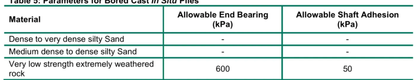
If structure loads cannot be economically supported on high level footings, bored cast in situ piles could be
considered. Piled footings should penetrate through the residual soil / colluvium and should extend at least three times their diameter into the weathered rock. Design of piles should be in accordance with Australian Standard AS2159-1995 Piling – Design and installation. Preliminary assessment of pile sizes and founding levels using static analyses could be based on the parameters presented in Table 5. For limit state strength design, a geotechnical strength reduction factor of 0.5 applied to the ultimate pressures is suggested. Selection of a design value for base capacity should consider materials four pile diameters below base level.
Table 5: Parameters for Bored Cast In Situ Piles
Note: Shaft adhesion and end bearing capacities in Table 5 apply when the pile length (L) is greater than 4 times the pile diameter (d). If L/d<4, use parameters for shallow footings. Design end bearing should consider material capacity within 4 pile diameters below founding level.
Founding Strata
Unit Weight ( )
Friction Angle
( ) Modulus (E) Pressure (Vertical)Allowable Bearing
Dense to very dense silty Sand 18 kN/m3 35 15 to 20 MPa 120 kPa
Medium dense to dense silty Sand 18 kN/m3 30 10 to 15 MPa 80 kPa
Engineered fill 18 kN/m3 30 10 to 20 MPa 100 kPa
Very low strength extremely
weathered rock 22 kN/m3 34 100 MPa 600 kPa
Material Allowable End Bearing (kPa) Allowable Shaft Adhesion (kPa)
Dense to very dense silty Sand - -
Medium dense to dense silty Sand - -
Very low strength extremely weathered
LOT 126, MURPHY STREET
April 2013
Report No. 137632049-001-R-Rev0 7
Bored pile settlements will depend on footing shape, applied load and pile cleanliness on casting concrete, and should be assessed once these characteristics are known. As a preliminary guide, footing settlements under static serviceability loads would not be expected to exceed about 1.5% of pile diameter for properly constructed bored piles using allowable bearing pressures presented in Table 5. Parameters are based on foundation excavations being clean, dry and free of loose, softened and disturbed materials at the time of pouring concrete.
It is recommended that bored pile drilling be logged by a geotechnical engineer to confirm ground conditions present and that geotechnical capacity meets the design loads.
5.4.3
Site Classification
In accordance with AS2870-1996 Residential slabs and footings – Construction’, the site is classified as
Class P due to uncontrolled fill and steep slopes. Footings should be designed in accordance with the parameters outlined above.
Based on site reactivity, the soil profile behaviour would be equivalent to a site with an S site classification.
5.5
Uncontrolled Fill
In the absence of an engineers certification, exiting fill is considered to be uncontrolled.
The uncontrolled fill is localised with relatively minor volumes. The uncontrolled fill is not considered suitable to support structural loads, and the uncontrolled fill has been shown to be marginally stable. It is our
understanding that the residential footings are planned to be extended into rock, therefore the uncontrolled fill is not deemed to be detrimental to stability of the residence. All landscape structures including driveways, garden walls, footpaths, etc. should likewise be founded in natural soil/rock beneath the uncontrolled fill, or on engineered fill.
5.6
Retaining Walls
For permanent retaining structures, it is recommended that drainage be provided behind all retaining structures to help prevent the development of water pressures on the back of the walls. In addition, the drainage will need to be maintained throughout the life of the structure. If the designer is not satisfied that maintenance will be undertaken and the integrity of drainage maintained, then the retaining structure design should allow for the development of water pressures.
Footings for retaining wall structures should be founded in rock or at least 0.5 m into the medium dense to dense or dense to very dense silty sands, the parameters presented in Table 4 should be used for design, along with the earth pressure coefficients presented in Table 6.
Table 6: Geotechnical Design Parameters for Retaining Walls Material Active Earth Pressure Coefficient (ka) At Rest Earth Pressure Coefficient (ko) Passive Earth Pressure Coefficient (ko) Unit Weight (kN/m3) Engineered fill / Colluvium 0.3* 0.47 3.0 18
Very Low and Low Strength Weathered
Rock
0.3 0.5 - 22
* Assumes horizontal backfill behind wall
Bearing pressures presented in Table 4 reduced by one-third for inclined resultant forces from lateral pressures could be used to size retaining wall footings.
All retaining wall excavations should be inspected by Golder to confirm the ground conditions are consistent with those on which these design guidelines are based.
LOT 126, MURPHY STREET
April 2013
Report No. 137632049-001-R-Rev0 8
6.0
LIMITATIONS
Your attention is drawn to the document Limitations, which is included in the appendices of this report. The statements presented in this document are intended to advise you of what your realistic expectations of this report should be. The document is not intended to reduce the level of responsibility accepted by Golder Associates, but rather to ensure that all parties who may rely on this report are aware of the responsibilities each assumes in so doing. We would be pleased to answer any questions about this important information from the reader of this report.
GOLDER ASSOCIATES PTY LTD
Gaozhao Lu Jules Darras
Geotechnical Engineer Principal Engineering Geologist
GZL/JJP/JD/dh
A.B.N. 64 006 107 857
Golder, Golder Associates and the GA globe design are trademarks of Golder Associates Corporation.
E E E E E E E E E E E E E E E E E E E E E E E E E E E E E E E E E E E E E E E E E E E E E E E E E E E E E E E E E E E E E E E E E E E E E E E E E RP 72 94 53 CO NC RETE DR AIN CO NC RE TE DR IVE WA Y CO NC RE TE DR IVE WA Y MU RPH Y S TREE T 25.0 26.0 27.0 28.0 29.0 30.0 31. 0 32 .0 33.0 37.0 A ? ? ? ? ? ? ? ? ? ? ? ? ? ? ? ? ? ? ? ? 29.0 30.0 32.0 33.0 34.0 35.0 36.0 38.0 39.0 40.0 42.0 43.0 44.0 OW EN S T. POIN T RD . MU RPH Y S T. MACR OSSA N ST . P lo t D a te : 9 A p ri l 2013 T im e: 1 :39 :12 PM B y : F a rl o w , A lan P a th : K :\G E O \2013 \137632049 - C W A G eo I n ve st L o t 126 M u rph y S tr ee t, P o rt D ou g la s\ F IG UR ES F ile N a m e: 137632 0 49 -001 -R -F 001 -F 002 -R e v0 .d wg C GOL DE R AS SO CIA TE S P TY . L TD . IN FO RM AT ION C ON TA IN ED ON T HIS DR AW IN G IS T HE C OP YR IGH T O F GO LD ER A SS OC IA TE S P TY . L TD . U NA UT HO RIS ED U SE OR R EP RO DUC TIO N O F T HIS P LA N E IT HE R W HO LLY OR IN PA RT W IT HO UT W RITT EN P ER MIS SIO N I NF RIN GE S C OP YR IGH T. X re f: G A P _ L O GO -A 3 .d w g ; 137632049 -X R E F -E xi st ing S it e F ea tu re s .d w g ; 137 6 32049 -X R E F -E G S u rv e y. d w g ; A 201_ R 3 .jpg ; B IN G IM A G E .J P G; DR A W IN G T IT LE P R O JE CT C LI E NT S C A LE S H E E T S IZE P R O JE C T No F IG UR E No R E V IS ION D O C No D O C T Y PE DR A W N BY CH E C K E D BY D A TE D A TE A3 www .go ld e r. com G O L D E R A SS O C IA T ES P T Y . LT D. 13 7632 049 001 R F 001 0 1 :200 S IT E I N V ES T IG A T IO N L O C A T IO N S A N D L O C A L IT Y P LAN - L O T 126 M U R P H Y S T R E E T , P O R T D O U G LAS L IN D S AY A N D R O B Y N P A R T R ID GE G E O T E CH N IC A L IN VE S T IG A T ION F IG UR E 1 1: 200 4 8 12m 0 N O T F O R C O N S T RU C T IO N I S S U E D F OR L E G E ND L O C A LI T Y P L A N P O R T D O U G L AS S IT E I N V ES T IG A T IO N L O C A T IO NS
EAS EM EN T B OUND ARY TP 1 D CP 1 ( 4.5 m S th) RE AL IT IVE L EV EL (m) TP 2 ( 1.0 m N th) CO NCRE TE DR AIN ? ? P lo t D a te : 9 A p ri l 2013 T im e: 1 :40 :39 PM B y : F a rl o w , A lan P a th : K :\G E O \2013 \137632049 - C W A G eo I n ve st L o t 126 M u rph y S tr ee t, P o rt D ou g la s\ F IG UR ES F ile N a m e: 137632 0 49 -001 -R -F 001 -F 002 -R e v0 .d wg C GOL DE R AS SO CIA TE S P TY . L TD . IN FO RM AT ION C ON TA IN ED ON T HIS DR AW IN G IS T HE C OP YR IGH T O F GO LD ER A SS OC IA TE S P TY . L TD . U NA UT HO RIS ED U SE OR R EP RO DUC TIO N O F T HIS P LA N E IT HE R W HO LLY OR IN PA RT W IT HO UT W RITT EN P ER MIS SIO N I NF RIN GE S C OP YR IGH T. X re f: G A P _ L O GO -A 3 .d w g ; 137632049 -X R E F -E xi st ing S it e F ea tu re s .d w g ; 137 6 32049 -X R E F -E G S u rv e y. d w g ; A 201_ R 3 .jpg ; B IN G IM A G E .J P G; DR A W IN G T IT LE P R O JE CT C LI E NT S C A LE S H E E T S IZE P R O JE C T No F IG UR E No R E V IS ION D O C No D O C T Y PE DR A W N BY CH E C K E D BY D A TE D A TE A3 www .go ld e r. com G O L D E R A SS O C IA T ES P T Y . LT D. 13 7632 049 001 R F 002 0 1 :200 S E C T IO N A - L O T 126 M U R P H Y S T R E E T , P O R T D O U G LAS L IN D S AY A N D R O B Y N P A R T R ID GE G E O T E CH N IC A L IN VE S T IG A T ION F IG UR E 2 1: 200 4 8 12m 0 N O T F O R C O N S T RU C T IO N I S S U E D F OR A
LOT 126, MURPHY STREET
April 2013
Report No. 137632049-001-R-Rev0 9
APPENDIX A
GAP Form No. 6 RL7 August 2010
EXPLANATION OF NOTES, ABBREVIATIONS & TERMS
USED ON BOREHOLE AND TEST PIT REPORTS
DRILLING/EXCAVATION METHOD
AS* Auger Screwing RD Rotary blade or drag bit NQ Diamond Core - 47 mm
AD* Auger Drilling RT Rotary Tricone bit NMLC Diamond Core - 52 mm
*V V-Bit RAB Rotary Air Blast HQ Diamond Core - 63 mm
*T TC-Bit, e.g. ADT RC Reverse Circulation HMLC Diamond Core – 63mm
HA Hand Auger PT Push Tube BH Tractor Mounted Backhoe
ADH Hollow Auger CT Cable Tool Rig EX Tracked Hydraulic Excavator
DTC Diatube Coring JET Jetting EE Existing Excavation
WB Washbore or Bailer NDD Non-destructive digging HAND Excavated by Hand Methods
PENETRATION/EXCAVATION RESISTANCE
L Low resistance. Rapid penetration possible with little effort from the equipment used.
M Medium resistance. Excavation/possible at an acceptable rate with moderate effort from the equipment used. H High resistance to penetration/excavation. Further penetration is possible at a slow rate and requires significant
effort from the equipment.
R Refusal or Practical Refusal. No further progress possible without the risk of damage or unacceptable wear to the digging implement or machine.
These assessments are subjective and are dependent on many factors including the equipment power, weight, condition of excavation or drilling tools, and the experience of the operator.
WATER
Water level at date shown Partial water loss
Water inflow Complete water loss
GROUNDWATER NOT OBSERVED
The observation of groundwater, whether present or not, was not possible due to drilling water, surface seepage or cave in of the borehole/test pit.
GROUNDWATER NOT ENCOUNTERED
The borehole/test pit was dry soon after excavation. However, groundwater could be present in less permeable strata. Inflow may have been observed had the borehole/test pit been left open for a longer period.
SAMPLING AND TESTING SPT 4,7,11 N=18 30/80mm RW HW HB
Standard Penetration Test to AS1289.6.3.1-2004
4,7,11 = Blows per 150mm. N = Blows per 300mm penetration following 150mm seating
Where practical refusal occurs, the blows and penetration for that interval are reported Penetration occurred under the rod weight only
Penetration occurred under the hammer and rod weight only Hammer double bouncing on anvil
DS Disturbed sample
BDS Bulk disturbed sample
G Gas Sample
W Water Sample
FP Field permeability test over section noted
FV Field vane shear test expressed as uncorrected shear strength (sv= peak value, sr = residual value)
PID Photoionisation Detector reading in ppm
PM Pressuremeter test over section noted
PP Pocket penetrometer test expressed as instrument reading in kPa
U63 Thin walled tube sample - number indicates nominal sample diameter in millimetres
WPT Water pressure tests
DCP Dynamic cone penetration test
CPT Static cone penetration test
CPTu Static cone penetration test with pore pressure (u) measurement
Ranking of Visually Observable Contamination and Odour (for specific soil contamination assessment projects) R = 0
R = 1 R = 2 R = 3
No visible evidence of contamination Slight evidence of visible contamination Visible contamination
Significant visible contamination
R = A R = B R = C R = D
No non-natural odours identified Slight non-natural odours identified Moderate non-natural odours identified Strong non-natural odours identified ROCK CORE RECOVERY
TCR = Total Core Recovery (%) SCR = Solid Core Recovery (%) RQD = Rock Quality Designation (%)
100 run core of Length ered cov re core of Length 100 run core of Length ered cov re core l cylindrica of Length 100 run core of Length mm 100 core of lengths Axial
GAP Form No. 5 RL8
METHOD OF SOIL DESCRIPTION
USED ON BOREHOLE AND TEST PIT REPORTS
Combinations of these basic symbols may be used to indicate mixed materials such as sandy clay. CLASSIFICATION AND INFERRED STRATIGRAPHY
Soil and Rock is classified and described in Reports of Boreholes and Test Pits using the preferred method given in
AS1726 1993, (Amdt1 1994 and Amdt2 1994), Appendix A. The material properties are assessed in the field by
visual/tactile methods.
Particle Size Plasticity Properties
Major Division Sub Division Particle Size BOULDERS > 200 mm COBBLES 63 to 200 mm Coarse 20 to 63 mm Medium 6.0 to 20 mm GRAVEL Fine 2.0 to 6.0 mm Coarse 0.6 to 2.0 mm Medium 0.2 to 0.6 mm SAND Fine 0.075 to 0.2 mm SILT 0.002 to 0.075 mm CLAY < 0.002 mm 0 10 20 30 40 0 10 20 30 40 50 60 70 80 Liquid Limit (%)
MOISTURE CONDITION AS1726 - 1993
Symbol Term Description
D Dry Sands and gravels are free flowing. Clays & Silts may be brittle or friable and powdery.
M Moist Soils are darker than in the dry condition & may feel cool. Sands and gravels tend to cohere.
W Wet Soils exude free water. Sands and gravels tend to cohere.
CONSISTENCY AND DENSITY AS1726 - 1993
Symbol Term Undrained Shear
Strength Symbol Term Density Index % SPT N #
VS Very Soft 0 to 12 kPa VL Very Loose Less than 15 0 to 4
S Soft 12 to 25 kPa L Loose 15 to 35 4 to 10
F Firm 25 to 50 kPa MD Medium Dense 35 to 65 10 to 30
St Stiff 50 to 100 kPa D Dense 65 to 85 30 to 50
VSt Very Stiff 100 to 200 kPa VD Very Dense Above 85 Above 50
H Hard Above 200 kPa
In the absence of test results, consistency and density may be assessed from correlations with the observed behaviour of the material.
# SPT correlations are not stated in AS1726 1993, and may be subject to corrections for overburden pressure and equipment type. FILL GRAVEL (GP or GW) SAND (SP or SW) SILT (ML or MH) CLAY (CL, CI or CH)
ORGANIC SOILS (OL or OH or Pt)
COBBLES or BOULDERS
CL Low plasticity
clay
CL/ML Clay/Silt OL or ML - Low liquid limit silt
CI Medium plasticity clay CH High plasticity clay OH or MH High liquid limit
silt
OL or ML Low liquid limit silt
LOT 126, MURPHY STREET
April 2013
Report No. 137632049-001-R-Rev0 10
APPENDIX B
Laboratory Test Results
LOT 126, MURPHY STREET
April 2013
Report No. 137632049-001-R-Rev0 11
APPENDIX C
Results of Stability Analysis
LOT 126, MURPHY STREET
April 2013
Report No. 137632049-001-R-Rev0 12
APPENDIX D
Limitations
LIMITATIONS
This Document has been provided by Golder Associates Pty Ltd (“Golder”) subject to the following limitations:
This Document has been prepared for the particular purpose outlined in Golder’s proposal and no responsibility is accepted for the use of this Document, in whole or in part, in other contexts or for any other purpose. The scope and the period of Golder’s Services are as described in Golder’s proposal, and are subject to restrictions and limitations. Golder did not perform a complete assessment of all possible conditions or circumstances that may exist at the site referenced in the Document. If a service is not expressly indicated, do not assume it has been provided. If a matter is not addressed, do not assume that any determination has been made by Golder in regards to it. Conditions may exist which were undetectable given the limited nature of the enquiry Golder was retained to undertake with respect to the site. Variations in conditions may occur between investigatory locations, and there may be special conditions pertaining to the site which have not been revealed by the investigation and which have not therefore been taken into account in the Document. Accordingly, additional studies and actions may be required.
In addition, it is recognised that the passage of time affects the information and assessment provided in this Document. Golder’s opinions are based upon information that existed at the time of the production of the Document. It is understood that the Services provided allowed Golder to form no more than an opinion of the actual conditions of the site at the time the site was visited and cannot be used to assess the effect of any subsequent changes in the quality of the site, or its surroundings, or any laws or regulations.
Any assessments made in this Document are based on the conditions indicated from published sources and the investigation described. No warranty is included, either express or implied, that the actual conditions will conform exactly to the assessments contained in this Document.
Where data supplied by the client or other external sources, including previous site investigation data, have been used, it has been assumed that the information is correct unless otherwise stated. No responsibility is accepted by Golder for incomplete or inaccurate data supplied by others.
Golder may have retained subconsultants affiliated with Golder to provide Services for the benefit of Golder. To the maximum extent allowed by law, the Client acknowledges and agrees it will not have any direct legal recourse to, and waives any claim, demand, or cause of action against, Golder’s affiliated companies, and their employees, officers and directors.
This Document is provided for sole use by the Client and is confidential to it and its professional advisers. No responsibility whatsoever for the contents of this Document will be accepted to any person other than the Client. Any use which a third party makes of this Document, or any reliance on or decisions to be made based on it, is the responsibility of such third parties. Golder accepts no responsibility for damages, if any, suffered by any third party as a result of decisions made or actions based on this Document.
Golder Associates Pty Ltd 216 Draper Street
Cairns, Queensland 4870 Australia