Validation of 3D motion tracking of pulmonary lesions using CT
fluoroscopy images for robotically assisted lung biopsy
Sheng Xu*
a, Gabor Fichtinger
a, Russell H. Taylor
a, Kevin Cleary
b aEngineering Research Center, Johns Hopkins University, Baltimore, MD, USA 21218
bImaging Science and Information Systems (ISIS) Center, Department of Radiology, Georgetown
University Medical Center, Washington DC, USA 20007
ABSTRACT
As recently proposed in our previous work, the two-dimensional CT fluoroscopy image series can be used to track the three-dimensional motion of a pulmonary lesion. The assumption is that the lung tissue is locally rigid, so that the real-time CT fluoroscopy image can be combined with a preoperative CT volume to infer the position of the lesion when the lesion is not in the CT fluoroscopy imaging plane. In this paper, we validate the basic properties of our tracking algorithm using a synthetic four-dimensional lung dataset. The motion tracking result is compared to the ground truth of the four-dimensional dataset. The optimal parameter configurations of the algorithm are discussed. The robustness and accuracy of the tracking algorithm are presented. The error analysis shows that the local rigidity error is the principle component of the tracking error. The error increases as the lesion moves away from the image region being registered. Using the synthetic four-dimensional lung data, the average tracking error over a complete respiratory cycle is 0.8 mm for target lesions inside the lung. As a result, the motion tracking algorithm can potentially alleviate the effect of respiratory motion in CT fluoroscopy-guided lung biopsy.
Keywords: Motion estimation, real-time tracking, robust tracking, data association, textured regions, lung biopsy,
robotics
1.
INTRODUCTION
In our previous work in image-guided lung biopsy, we developed an algorithm based on CT fluoroscopy images to track the three-dimensional motion of the pulmonary lesion in real-time1. While the algorithm was designed for image-guided robotically assisted lung biopsy, it also has other potential applications. For example, in treatment planning, accurate tumor tracking can provide us with a better understanding of the lung tumor motion. This knowledge can improve the precision of radiation therapy for lung cancer patients and allow for increased tumor dose and decreased normal tissue dose2. The algorithm can also be used to reconstruct four dimensional lung data, allowing full investigation of the respiratory motion for the entire lung. With the patient breathing freely under the continuous CT scan, the algorithm can directly synchronize the scanning time of each CT image with the respiratory cycle by tracking the lung motion. The lung volume at any respiratory phase can be reconstructed from the CT images obtained at different respiratory cycles.
To investigate the lung motion, the tracking algorithm can work as a low level component of other high level methods (such as the Kalman filter3). In this paper, we present experimental results designed to characterize the properties of the tracking algorithm. The motion tracking algorithm of this paper is a variation of the optical flow method that is widely used in computer vision. It is usually hard to validate this kind of algorithm because of the difficulty of obtaining the ground truth. In this paper, we use a synthetic four-dimensional lung dataset as the ground truth to test the accuracy and robustness of the tracking algorithm.
2.
METHODS
We use a lung data set obtained from Siemens Corporate Research (Princeton, NJ) to validate the algorithm. The validation procedure is illustrated in Figure 1. The gray boxes represent the original data from Siemens. The displacement field is generated from two registered lung volumes. One of the volumes is obtained at the end of inspiration; the other one at the end of expiration. The two volumes were registered by Siemens researchers using 3D/3D deformable registration. The displacement field associates each pixel of the preoperative CT volume with a 3D vector, indicating the motion of the pixel from the end-of-expiration to the end-of-inspiration. By interpolating the 3D vector of each pixel over a complete respiratory cycle, the respiratory motion trajectory of each pixel can be obtained. This trajectory is considered as the ground-truth motion of every lung pixel to validate the tracking algorithm.
Figure.1: Workflow of the validation. The gray boxes denote the original data.
Figure 2: Interpolated displacement of a lung pixel (solid lines). The dash lines represent the pixel displacement without disturbance.
According to the ground-truth trajectory of each pixel during a respiratory cycle, the preoperative 3D CT volume is deformed to synthesize the 4D lung data. The CT fluoroscopy image sequence is synthesized by sampling the 4D data at a selected CT table position over a complete respiratory cycle. The tracking algorithm then processes the CT fluoroscopy images to estimate the respiratory motion trajectory of the target. By comparing the tracking results with the ground-truth trajectory, the target-tracking algorithm is validated.
The following formula is used to interpolate the displacement field:
(
)
T
x
y
z
T
(
x
y
z
t
)
t
t
z
y
x
,
,
,
2
,
,
,
2
2
2
sin
1
,
,
,
d
d
d
+
∆
•
•
−
+
=
π
π
(1)where T is the period of the respiratory motion; the respiratory phase of the preoperative CT (end-of-expiration) is used as the reference respiratory phase 0; T/2 is the respiratory phase of the end of inspiration;
d
(
x
,
y
,
z
,
t
)
represents the interpolated displacement of pixel (x, y, z) at time t;d
(
x
,
y
,
z
,
T
/
2
)
is the ground-truth displacement of the pixel from the end-of-expiration to the end-of-inspiration; and∆
d
is a smooth nonlinear function of x, y, z and t. Without∆
d
,(
x
,
y
,
z
,
t
)
d
is a scaled version ofd
(
x
,
y
,
z
,
T
/
2
)
, and the trajectory of pixel (x, y, z) is a straight line in space.∆
d
is artificially introduced to assure that the trajectory of pixel (x, y, z) is a 3D curve in space. The interpolated displacement of a lung pixel over a respiratory cycle is shown in Figure 2.
2.1 Lesion tracking algorithm review
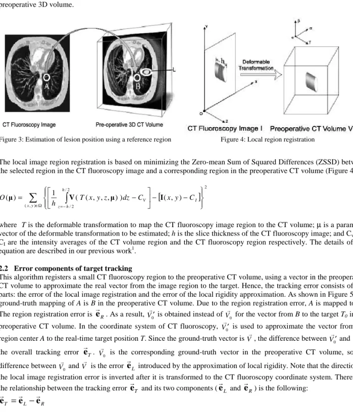
In our previous work1, we proposed an algorithm to track the respiratory motion of a target lesion using 2D CT fluoroscopy images. The algorithm assumes the lung to be locally rigid. When the target is outside the imaging plane, its position can be estimated from a reference in the imaging plane and an offset from the reference to the target. The goal of the algorithm is to find a 3D vector pointing from the reference in the imaging plane to the target lesion in space. To find this vector, a small region A is selected in the CT fluoroscopy image such that the region is close to the target lesion and has rich texture (Figure 3). By registering the local region A to its corresponding region B of the pre-operative CT volume, the 3D vector from A to the target can be estimated from the relative position between B and the lesion in the preoperative 3D volume.
Figure 3: Estimation of lesion position using a reference region Figure 4: Local region registration
The local image region registration is based on minimizing the Zero-mean Sum of Squared Differences (ZSSD) between the selected region in the CT fluoroscopy image and a corresponding region in the preoperative CT volume (Figure 4).
[
]
∑
∈Ω =−∫
− − − = ) , ( 2 2 / 2 / ) , ( ) ) , , , ( ( 1 ) ( y x I V h h z C y x C dz z y x T h O µ V µ I (2)where T is the deformable transformation to map the CT fluoroscopy image region to the CT volume; µ is a parameter vector of the deformable transformation to be estimated; h is the slice thickness of the CT fluoroscopy image; and Cv and
CI are the intensity averages of the CT volume region and the CT fluoroscopy region respectively. The details of this
equation are described in our previous work1.
2.2 Error components of target tracking
This algorithm registers a small CT fluoroscopy region to the preoperative CT volume, using a vector in the preoperative CT volume to approximate the real vector from the image region to the target. Hence, the tracking error consists of two parts: the error of the local image registration and the error of the local rigidity approximation. As shown in Figure 5, the ground-truth mapping of A is B in the preoperative CT volume. Due to the region registration error, A is mapped to B’. The region registration error is
e
R. As a result, V0′ is obtained instead of V0 for the vector from B to the target T0 in the
preoperative CT volume. In the coordinate system of CT fluoroscopy, V0′ is used to approximate the vector from the region center A to the real-time target position T. Since the ground-truth vector is V, the difference between
0
V′ and V is the overall tracking error
e
T. V0 is the corresponding ground-truth vector in the preoperative CT volume, so the difference between V0 and V is the errore
L introduced by the approximation of local rigidity. Note that the direction of the local image registration error is inverted after it is transformed to the CT fluoroscopy coordinate system. Therefore, the relationship between the tracking errore
T and its two components (e
L ande
R) is the following:R L T
e
e
Figure 5: Error components of target tracking
2.3 Local image region registration
2.3.1 Local image region
The size of the image region is associated with the number of least square equations to solve equation (2). A large region size allows the motion tracking algorithm to have more texture information for the local registration. It reduces the local minima and makes the algorithm more robust. The downside is that the algorithm loses its resolution as the region size increases, because the result of the algorithm is the overall deformable transformation of the entire region. Hence, the region should be as small as possible as long as the objective function can converge correctly. It is desirable to configure the region size such that the algorithm can have the best overall accuracy and robustness.
In the tracking algorithm, the disk-shaped region is used because (a) it can better approximate the deformation of the region with respect to its surrounding area; and (b) it has a smaller area than other shapes with the same perimeter. The multi-resolution strategy can be used to increase the robustness of the algorithm in directions parallel to the imaging plane. For the direction perpendicular to the imaging plane, the multi-start strategy can help if the respiratory motion is fast or the CT fluoroscopy rate is slow.
2.3.2 Deformable transformation model
The formulation of the objective function is most effective for transformation models that are linear in their parameters4. There are many choices for the transformation model. The simplest model is the translation transformation that has only three degrees of freedom (DOF). More complicated models include the rigid-body, affine, and quadratic transformations. They have six, twelve, and thirty DOF respectively. In general, using a model with more DOF can account for more complicated deformation of the region and thus obtain a better registration accuracy. But more DOF can also result in a less stable objective function and more local minima. In this research, since the image region to be registered is very small, the deformation of the region is relatively simple. Only the rigid-body, affine and quadratic transformations are investigated. More complicated transformations are not necessary.
2.3.2 Slice thickness of the CT fluoroscopy image
The slice thickness used in equation (2) is an important parameter related to the computational time of the algorithm. As shown in Figure 4, changing the CT fluoroscopy image slice thickness corresponds to a change in subvolume size in the preoperative CT volume. The larger the subvolume, the more pixels are sampled to generate the synthetic image region, and the more time consuming the algorithm is.
The slice thickness also affects the robustness and accuracy of the algorithm. A large slice thickness has a similar effect as smoothing the Z-direction using a rectangular window. Smoothing is necessary for the algorithm to converge correctly. As described in [1], the CT fluoroscopy image can only be smoothed on a slice-by-slice basis. Although each pixel of the CT fluoroscopy image represents a pixel in 3D space, it is impossible to smooth a single 2D image in the direction perpendicular to the imaging plane. Therefore, a relatively large slice thickness can compensate for the
smoothing operation of the 2D image and improve the robustness of the algorithm. On the other hand, the slice thickness cannot be too large, or the registration accuracy along the Z-axis will be poor. Therefore, an appropriate slice thickness is desired to achieve the best performance of the algorithm.
2.4 Local rigidity approximation
The goal of the tracking algorithm is to find a 3D vector pointing from a reference in the CT fluoroscopy imaging plane to the target lesion. As described in Section 2.1, this vector can be estimated from the preoperative CT volume. The assumption is that the lung is locally rigid during the respiratory motion. In other words, that relative position between the target and the reference does not change. This approximation may not be accurate during the whole respiratory cycle. It is a good estimation only when the reference and the target lesion are very close to each other. Since different patients may have different lung stiffnesses, the estimation error is also patient related. Even for the same patient, the error varies depending on the location of the target lesion. For example, with the patient in a supine position, the estimation error is larger in the anterior lung than in the posterior lung because the anterior lung has greater respiratory motion. Therefore, it is very difficult to obtain a good estimation of the local rigidity error in practice.
The tracking algorithm uses the center of the image region as the reference point. Since the local rigidity error increases as the distance between the region and target increases, it is very important to make the region as close as possible to the target lesion. For a target lesion that is not near the lung boundary, its projection on the imaging plane is the best choice of the region center, because the distance between the target and the region is the shortest.
3.
EXPERIMENTAL RESULTS
The pixel size of both the preoperative CT volume and the 2D images is 0.7422mm. The slice thickness of the preoperative CT volume is 1.25mm, and 3.75mm for the synthetic 2D free scan images. In order to give quantitative analysis, the validation was carried out using the most basic algorithm configurations. Neither resolution nor multi-start techniques were used to increase the convergence region. No temporal filters were used to smooth the tracking results. The validation was designed to show the most basic properties of the algorithm.
3.1 Robustness and accuracy of the local region registration
The transformation model, slice thickness, and region size all influence the robustness and accuracy of the algorithm. The following studies were carried out to find the best combination of these parameters. Since all the region registrations were performed locally, the overall validation result was not data specific.
Initially, a 3D lung volume was reconstructed by sampling the 4D lung data set at the end of inspiration. As shown in Figure 2, the end of inspiration is the respiratory phase with the maximum displacement from the preoperative CT volume. Two hundred and twenty testing points were uniformly selected by sampling the 3D lung volume. Automated lung segmentation11 was used to assure that all the testing points are neither outside the lung nor near the lung boundary. For each testing point, a CT fluoroscopy image containing this point was synthesized by sampling the 3D volume at a CT table position. An image region was then centered on this testing point in the synthesized CT fluoroscopy image. Using equation (2), the 2D region could be registered to the 3D preoperative volume to find the corresponding position of the testing point. Since equation (2) was solved iteratively using the Gauss-Newton method5, the goal of this experiment was to find the size of the convergence region of the local registration.
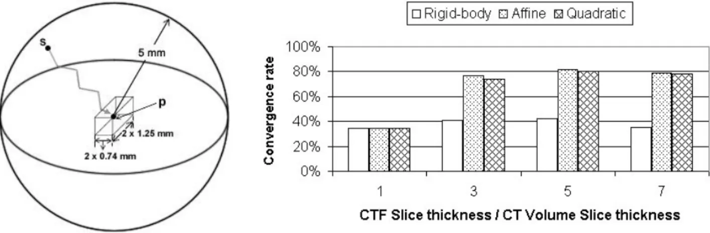
Because the 2D image region was synthesized from the 4D data, the ground-truth mapping of the testing point in the preoperative CT volume is known. As shown in Figure 6, the convergence region is denoted by a ball centered on the ground truth mapping of the testing point. By definition, the algorithm can converge to the ground truth
p
from any positions
inside the ball. In reality, the shape of the convergence region can be very complicated. However, the convergence rate of the starting points inside the ball can be used to measure the size of the convergence region of the testing point. The average convergence rate of all the testing points can be used as the robustness measure of the local region registration algorithm. In this experiment, the following approach was used to define the convergence of the algorithm.Figure 6: Convergence region estimation Figure 7: Registration convergence rate under different configurations
The local region registration algorithm uses finite differences to calculate the gradient image1. The accuracy of the local registration should be at the subpixel level. Therefore, if a registration result is within one pixel distance from the ground truth, it is classified as correctly converged. The radius of the ball in Figure 6 is 5mm. The box in the center represents the boundary of the correctly converged results. The size of the box is two times the pixel size of the preoperative CT volume. Fifty-six starting points were uniformly sampled in the ball.
Figure 7 shows the average convergence rate of all the testing points using different slice thicknesses and transformation models. The horizontal axis is the slice thickness of the CT fluoroscopy divided by the slice thickness of the preoperative CT. Several facts can be observed:
(a) the affine transformation performed better than the other two transformations. The same result was obtained at different slice thickness, which also confirmed the correctness of the robustness measure.
(b) The rigid-body transformation was the worst of the three transformations. This was because the deformation of the lung region was under-modeled. The accuracy of rigid-body registration could be bad even if the algorithm converged correctly.
(c) Using the quadratic transformation did not improve the registration accuracy, suggesting that more complicated transformations may not be helpful. The region radius to generate Figure 6 was 11.88 mm or 16 pixels. Although it was possible to use a smaller region to improve the algorithm accuracy, it could also increase the possibility of failure because the smaller region has less texture. The same experiment was also carried out with a region radius of 20 pixels. Similar results were observed, but the overall performance of the algorithm was slightly worse. It is worthwhile to point out that the local registration algorithm resulted in a very bad performance when the slice thickness of the CT fluoroscopy image was the same as that of the preoperative CT volume. In this case, the objective function (2) was not smoothed in the direction perpendicular to the imaging plane. It was very easy for the algorithm to converge to the wrong local minima.
With the appropriate slice thickness, transformation model and region size, the convergence rate of the local region registration was above 80% for all the starting points within 5mm from the ground truth. This convergence region is large enough for the algorithm to follow the regular respiratory motion. The sample rate for the CT fluoroscopy images is usually very high. It is unlikely for the tumor to move more than 5mm between two consecutive CT fluoroscopy image frames6. The convergence region can be even larger after using other high level techniques7, 8 such as the multi-resolution9 and multi-start strategies10. Applying the temporal filter3 on the target trajectory can also boost the robustness of the algorithm.
Although the Z axis (craniocaudal) plays a very different role in the motion tracking algorithm compared to the X axis (left-right) and the Y axis (anterior-posterior), there is no significant difference in accuracy among X, Y and Z. Table 1 shows the average error of the local region registration.
Table 1. Components of local region registration error
Average Error
X component 0.11 mm
Y component 0.09 mm
Z component 0.12 mm
Table 2. Overall tracking error and its components
Average Error
Overall tracking algorithm 0.79 mm Local region registration 0.23 mm Local rigidity approximation 0.75 mm
3.2 Overall accuracy
To validate the overall accuracy of the tracking algorithm, fifteen uniformly distributed targets were selected in the lung. Fifty frames of CT fluoroscopy images were sampled over a complete respiratory cycle. As a result, the trajectory of each target consisted of fifty points in space. To minimize the local rigidity error, the target projection on the imaging plane was used as the region center. The slice thickness of the CT fluoroscopy image was 5.75 mm or five times the slice thickness of the preoperative CT volume. The affine transformation was used to model the deformable transformation of the local image region. The radius of the region was 11.88 mm or 16 pixels. If the algorithm failed to register an image region at a time point, the tracking result of the target at the time point was discarded. Due to the large convergence of the local registration, the algorithm could recover from all the failures in the following several CT fluoroscopy frames.
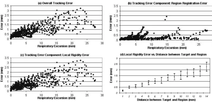
Figure 8: Motion tracking error. (a) overall tracking error; (b) error of local image region registration; (c) error of local rigidity approximation; (d) error of local rigidity and the variance of the error.
As shown in Figure 8, the error introduced by the local rigidity approximation is the dominant component of the overall tracking error. The further the target is from the image region, the larger the local rigidity error is regardless of the accuracy of the local image region registration. The variance of the local rigidity error also increases as the target moves away from the image region (Figure 8(d)), suggesting that the local rigidity error becomes more and more unpredictable. For this particular lung dataset, the average local rigidity error is approximately 18% of the distance between the target and the image region. Table 2 shows the average tracking error compared to the average registration error and local rigidity error.
4.
DISCUSSION
In the above validation, all the target points were selected inside the lung to assure that the image region centered on the target projection on the imaging plane only has lung pixels. For the target point on the lung boundary, its projection is near the lung boundary. In this case, the region could include non-lung pixels if it is still centered on the target projection. Since the registration algorithm requires all pixels inside the region to have the same type of motion, the region has to be moved away from the target projection to make sure the region has only lung pixels. Hence, the distance
between the target and the image region increases. The motion tracking accuracy of the boundary targets will be worse than that of the in-lung targets.
The local region registration maps not only the region center but also the rest of the pixels in the region to the preoperative CT volume. As a result, any pixel inside the region can be used as a reference point, and the 3D vector will be from the reference point to the target. This feature gives us the freedom to position the local image region on a lung area with relative rich texture, and thus makes the algorithm more robust. The advantage of using the region center as the reference is that the center pixel usually has better registration accuracy than other pixels in the region.
Although the motion tracking algorithm loses accuracy when the target lesion moves away from the imaging plane, the algorithm could still be very useful in image-guided robotically assisted lung biopsy, because the robot can wait for the target to come back into the high accuracy zone. Once the target is near the imaging plane, the robot can make quick adjustments and insert the needle. In addition, if the CT table is controllable by the computer, the target tracking result can be used to adjust the CT table to make the lesion stay in the imaging plane all the time even under the patient’s respiratory motion.
5.
CONCLUSION
The motion tracking algorithm is most effective when the target lesion is near the imaging plane. The tracking error rises as the target moves away from the imaging plane. The principal component of the tracking error comes from the local rigidity approximation. For the lung dataset used in this validation, the local rigidity error is approximately 18% of the distance from the image region to the target. With appropriate configurations of the slice thickness, deformation transformation and the region size, the convergence region of the registration algorithm can be large enough to follow the respiratory motion. Although the target tracking is not failure free, it can recover from failure by itself. In addition, there is great potential to make the algorithm more robust by integrating it with some high-level control methods. In lung biopsy, a lesion is considered to be small if its radius is less than 7.5 mm12. The tracking algorithm has much better accuracy than this level. Moreover, the robot can wait for the lesion to come back in the high accuracy zone and then insert the needle. As a result, the motion tracking algorithm can compensate for most respiratory motion and thus potentially improve the performance of the image-guided robotically assisted lung biopsy, which will be studied in future research.
6.
ACKNOWLEDGMENT
The authors would like to thank Frank Sauer, Ph.D. and Christophe Chefd’hotel, Ph.D. at Siemens Corporate Research for providing the lung dataset. The authors also thank David Lindisch, RT, for his assistance with the experiments at Georgetown University. This work was primarily supported by U.S. Army grant DAMD17-99-1-9022 and National Cancer Institute (NIH) grant 1 R21 CA094274-01A1. Research infrastructure was also provided by the National Science Foundation under ERC cooperative agreement EEC9731478.
7.
REFERENCES
1. S. Xu, G. Fichtinger, R. Taylor, K. Cleary, “3D Motion Tracking of Pulmonary Lesions Using CT Fluoroscopy Images for Robotically Assisted Lung Biopsy”, Proc. SPIE Int. Soc. Optical Engineering, vol. 5367, pp. 394-402, 2004.
2. P. Keall, “4-Dimensional computed tomography imaging and treatment planning,” Seminars in Radiation Oncology, vol. 14(1), pp. 81-90, 2004
3. M. Kohler, “Using the Kalman Filter to track Human Interactive Motion Modeling and Initialization of the Kalman Filter for Translational Motion”, Technical Report No. 629, University Dortmund, 1997.
4. Jason J. Corso, Nicholas Ramey, and Gregory D. Hager, “Stereo-Based Direct Surface Tracking with Deformable Parametric Models”, Technical Report 02, The Johns Hopkins University, 2003.
5. G. Hager and P. Belhumeur, “Efficient Region Tracking With Parametric Models of Geometry and Illumination”, IEEE Trans. on Pattern Analysis and Machine Intelligence, vol. 20(10), pp. 1205-1039, 1998.
6. K Forster, C Stevens, K Kitamura, G Starkschall, H Liu, Z Liao, J Chang, J Cox, M Jeter, T Guerrero, R Komaki, “3D Assessment of Respiration Induced NSCLC Tumor Motion”, 45th annual meeting of the American Association of Physicists in Medicine, 2003.
7. K. Toyama and G. Hager, “Incremental Focus of Attention for Robust Vision-Based Tracking”, Intl. J. Computer Vision, vol. 35(1), pp. 45-63, 1999
8. B. McCane, B. Galvin, K. Novins, “Algorithmic Fusion for More Robust Feature Tracking”, Intl. J. of Computer Vision, vol. 49(1), pp. 79-89, 2002.
9. S. Krüger, “Motion Analysis and Estimation using Multiresolution Affine Models”, Ph.D. thesis, University of
Bristol, 1998.
10. J. V. Hajnal, D. L.G. Hill, D. J. Hawkes, Medical Image Registration, CRC Press LLC, 2001.
11. S. Hu and E. A. Hoffman, “Automatic Lung Segmentation for Accurate Quantitation of Volumetric X-Ray CT Images”, IEEE Trans. Medical Imaging, vol. 20(6), 2001.
12. N. Tomiyama,N. Mihara, M. Maeda, T. Johkoh, T. Kozuka, O. Honda, S. Hamada, S. Yoshida, H. Nakamura, “CT-guided needle biopsy of small pulmonary nodules: value of respiratory gating”, Radiology, vol.217(3), pp. 907-10, 2000 Dec.