42 | P a g e
Experimental analysis of I-V and P-V characteristics for
series and parallel combination of PV modules
Hitesh M. Karkar
1, Dr. I. N. Trivedi
21.
Ph.D. Scholar, Gujarat Technological University, Ahmedabad
Assistant Professor, L. E. College, Morbi, India.
2.
Associate Professor, Electrical Engineering Department, GEC Gandhinagar, India.
ABSTRACT
The renewable energy has increased much attraction these days as it can be recycled. The solar energy can be
able to transform solar energy in to electrical energy, which is more efficient than other renewable sources. PV module is characterized by its I-V and P-V characteristics. The output power of PV system is always changing with whether condition. Thus the proposed system should present the experimental analysis showing the I-V and
P-V characteristics of PV system under different temperature and irradiation with two panels are connected in
series and parallel. The experimental analysis provides that the effect of irradiation and temperature on series and parallel connected PV module. It has been performed by using solar PV panel.
Keywords
-
Characteristic,
Irradiation
, I-V, P-V, PV module, Temperature
1.
INTRODUCTION
A solar cell is a device that converts the energy of sunlight directly into electricity by the photovoltaic effect.
Sometimes the term solar cell is reserved for devices intended specifically to capture energy from sunlight. The
most commonly known solar cell is configured as a large area p-n junction made from silicon. As a
simplification, one can imagine bringing a layer of n-type silicon into direct contact with a layer of p-type
silicon. In practice, p-n junctions of silicon solar cells are not made in this way, but rather by diffusing an n-type
doping into one side of a p-type wafer (or vice versa) on of PV modules.
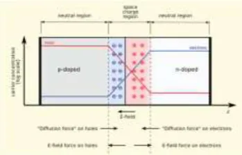
As per Fig. 1 if a piece of p-type silicon is placed in intimate contact with a piece of n-type silicon, then a
diffusion of electrons occurs from the region of high electron concentration (the n-type side of the junction) into
the region of low electron concentration (p-type side of the junction). When the electrons diffuse across the p-n
junction, they recombine with holes on the p-type side. The diffusion of carriers does not happen indefinitely,
however, because charges build up on either side of the junction and create an electric field which prevents the
further diffusion of charge carriers. The region where electrons and holes have diffused across the junction is
called the depletion region because it no longer contains any mobile charge carriers. It is also known as the
43 | P a g e
Fig. 1 Formation of P-N junctionWhen a photon hits a piece of silicon, one of three things can happen
1) The photon can pass straight through the silicon — this (generally) happens for lower energy photons,
2) The photon can reflect off the surface,
3) The photon can be absorbed by the silicon, if the photon energy is higher than the silicon band gap value.
This generates an electron-hole pair and sometimes heat, depending on the band structure.
When a photon is absorbed, its energy is given to an electron in the crystal lattice. Usually this electron is
in the valence band, and is tightly bound in covalent bonds between neighboring atoms, and hence unable to
move far. The energy given to it by the photon "excites" it into the conduction band, where it is free to move
around within the semiconductor. The covalent bond that the electron was previously a part of now has one
fewer electron — this is known as a hole. The presence of a missing covalent bond allows the bonded electrons
of neighboring atoms to move into the "hole," leaving another hole behind, and in this way a hole can move
through the lattice. Thus, it can be said that photons absorbed in the semiconductor create mobile electron-hole
pairs. These mobile charge carriers are responsible for the current conduction across the junction.
2.
CHARACTERISTIC CURVES
Solar cell can be represented by an equivalent circuit also. This circuit also includes the losses due to the solar
cell manufacturing process. In this circuit Rs is the series resistance associated with the cell which is due to the
grids above the solar cells and interconnection of solar cells. 𝑅𝑠ℎ is the parallel resistance with cell which
represents the leakage current through the cell. Equivalent circuit of cell is shown in Fig. 2.
Fig. 2 Equivalent Circuit of Solar PV Cell
PV module is characterized by its I-V and P-V characteristics. At a particular level of solar insolation and
44 | P a g e
requirement by connecting both modules in series or parallel to get higher voltage or higher current as shown inFig. 3(a) and 3(b) respectively.
Fig. 3(a) I-V characteristic of series connected modules
Fig. 3(b) I-V characteristic of parallel connected modules
Therefore, if modules are connected in series then power reduction is twice when connected in parallel.
On changing the solar insolation, 𝐼𝑠𝑐 of the module increases while the 𝑉𝑜𝑐 increases very slightly, therefore
there is overall power increase. In parallel connection power increment is twice than when connected in series.
3.
EXPERIMENTAL SET-UP
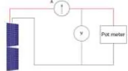
The circuit diagram to evaluate I-V and P-V characteristics of modules connected in series and parallel are
shown in Fig. 4(a) and 4(b) respectively.
Form a PV system with modules in either series or parallel and a variable resistor (Pot meter) with
ammeter and voltmeter for measurement. Modules in series or parallel are connected to variable load (pot
meter). The effect of load change on output voltage and current of the modules connected in series or parallel
can be seen by varying load resistance (pot meter).
Fig. 4(a) Circuit diagram for evaluation of I-V and P-V characteristics of series connected modules
45 | P a g e
4.
EXPERIMENT RESULT
PV module is characterized by its I-V and P-V characteristics at particular solar irradiation and
temperature. I-V characteristics maximum current at zero voltage is the short circuit current (𝐼𝑠𝑐) which can be
measured by shorting of PV module and maximum voltage at zero current is the open circuit voltage (𝑉𝑜𝑐). On
changing the solar isolation 𝐼𝑠𝑐 of the module increases while the 𝑉𝑜𝑐 increase very slightly. When both modules
connected in series and parallel the effect of irradiance and temperature is given below.
4.1 Two series connected PV module with varying Radiation and Temperature:
PV module when it is connected in series the effects of solar irradiation and temperature on of I-V and
P-V characteristics at particular condition as shown below.
Table I. 200 W/m2 radiation for two parallel connected PV modules
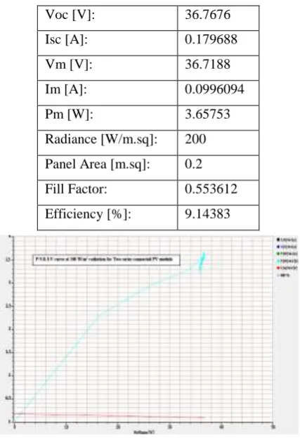
Fig. 5 P-V and I-V characteristics at 200 W/m2 for two series connected PV modules
Table II.400 W/m2 radiation for two series connected PV modules
Voc [V]: 36.7676
Isc [A]: 0.179688
Vm [V]: 36.7188
Im [A]: 0.0996094
Pm [W]: 3.65753
Radiance [W/m.sq]: 200
Panel Area [m.sq]: 0.2
Fill Factor: 0.553612
Efficiency [%]: 9.14383
Voc [V]: 36.7676
Isc [A]: 0.179688
46 | P a g e
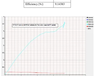
Fig. 6 P-V and I-V characteristics at 400 W/m2 for two series connected PV modules
Table III. 600 W/m2 radiation for two series connected PV modules
Im [A]: 0.0996094
Pm [W]: 3.65753
Radiance [W/m.sq]: 200
Panel Area [m.sq]: 0.2
Fill Factor: 0.553612
Efficiency [%]: 9.14383
Voc [V]: 38.7207
Isc [A]: 0.232422
Vm [V]: 35.0098
Im [A]: 0.189453
Pm [W]: 6.63271
Radiance [W/m.sq]: 600
Panel Area [m.sq]: 0.2
Fill Factor: 0.737006
47 | P a g e
Fig. 7 P-V and I-V characteristics at 600 W/m2 for two series connected PV modules
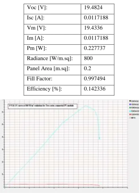
Table IV. 800 W/m2 radiation for two series connected PV modules
Fig. 8 P-V and I-V characteristics at 800 W/m2 for two series connected PV modules
Table V.1000 W/m2 radiation for two series connected PV modules Voc [V]: 19.4824
Isc [A]: 0.0117188
Vm [V]: 19.4336
Im [A]: 0.0117188
Pm [W]: 0.227737
Radiance [W/m.sq]: 800
Panel Area [m.sq]: 0.2
Fill Factor: 0.997494
Efficiency [%]: 0.142336
Voc [V]: 19.5312
Isc [A]: 0.0117188
48 | P a g e
4.2 Two Parallel Connected PV Module With Varying Radiation and Temperature:
PV module when it is connected in parallel the effects of solar irradiation and temperature on of I-V
and P-V characteristics at particular condition as shown below.
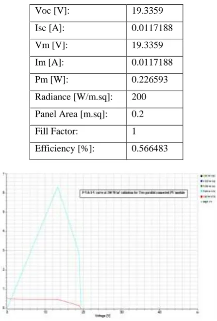
Table VI. 200 W/m2 radiation for two parallel connected PV modules
Fig. 9 P-V and I-V characteristics at 200 W/m2 for two parallel connected PV modules
Im [A]: 0.0117188
Pm [W]: 0.227737
Radiance [W/m.sq]: 1000
Panel Area [m.sq]: 0.2
Fill Factor: 0.995
Efficiency [%]: 0.113869
Voc [V]: 19.3359
Isc [A]: 0.0117188
Vm [V]: 19.3359
Im [A]: 0.0117188
Pm [W]: 0.226593
Radiance [W/m.sq]: 200
Panel Area [m.sq]: 0.2
Fill Factor: 1
49 | P a g e
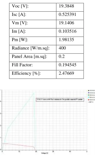
Table VII. 400 W/m2 radiation for two parallel connected PV modules
Fig. 10 P-V and I-V characteristics at 400 W/m2 for two parallel connected PV modules
Table VIII. 600 W/m2 radiation for two parallel connected PV modules
Voc [V]: 19.3848
Isc [A]: 0.525391
Vm [V]: 19.1406
Im [A]: 0.103516
Pm [W]: 1.98135
Radiance [W/m.sq]: 400
Panel Area [m.sq]: 0.2
Fill Factor: 0.194545
Efficiency [%]: 2.47669
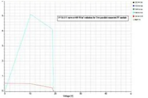
Voc [V]: 19.4824
Isc [A]: 0.523438
Vm [V]: 18.1641
Im [A]: 0.304688
Pm [W]: 5.53436
Radiance [W/m.sq]: 600
Panel Area [m.sq]: 0.2
Fill Factor: 0.5427
50 | P a g e
Fig. 11 P-V and I-V characteristics at 600 W/m2 for two parallel connected PV modules
Table IX. 800 W/m2 radiation for two parallel connected PV modules
Fig. 12 P-V and I-V characteristics at 800 W/m2 for two parallel connected PV modules
Voc [V]: 19.4824
Isc [A]: 0.0117188
Vm [V]: 19.4336
Im [A]: 0.0117188
Pm [W]: 0.227737
Radiance [W/m.sq]: 800
Panel Area [m.sq]: 0.2
Fill Factor: 0.997494
51 | P a g e
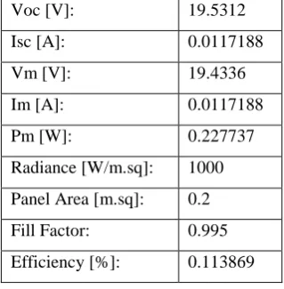
Table X. 1000 W/m2 radiation for two parallel connected PV modules
Fig. 13 P-V and I-V characteristics at 1000 W/m2 for two parallel connected PV modules
4.3 Comparison of Two Series and Parallel connected PV module with varying radiation and
temperature effect
Table XI: Two series connected PV modules
Sr. No. Radiation (W/m2) Temp. (Deg.) Voltage (V) Current (A) Power (W)
1 200 37.6 38.67 0.102 3.928
2 400 36.9 38.92 0.105 4.104
3 600 35.4 39.06 0.105 4.121
4 800 33.9 39.36 0.111 4.381
5 1000 32.3 39.6 0.109 4.331
Table XII: Two parallel connected PV modules
Sr. No. Radiation (W/m2) Temp. (Deg.) Voltage (V) Current (A) Power (W)
1 200 40 19.3359 0.009766 0.226593
Voc [V]: 19.5312
Isc [A]: 0.0117188
Vm [V]: 19.4336
Im [A]: 0.0117188
Pm [W]: 0.227737
Radiance [W/m.sq]: 1000
Panel Area [m.sq]: 0.2
Fill Factor: 0.995
52 | P a g e
2 400 39.6 19.1406 0.009766 1.981353
3 600 38.9 19.4824 0.304688 0.228313
4 800 38.4 19.5336 0.505859 0.227737
5 1000 37.3 19.4336 0.505859 0.227737
This section describes the criteria used to investigate solar irradiation and temperature is the factors
with greater influence in the maximum peak of available power from a PV array. It is worth mentoring that
the arrangement of PV modules in series and parallel connection is directly related to the efficiency of the
system. From this experiments on solar panels, four different situation were performed to determine the
criteria of comparison that both the two panels are connected in series with temperature fixed at 35˚C and
irradiance in variable then same series connection irradiance is fixed at 1000 W/sq.m and temperature is
fixed. Then same experiments done both the panels are connected in parallel. The standard test condition of
this panel temperature is 25˚C and solar irradiation is 1000 W/sq.m.
5.
CONCLUSION
On increasing the temperature, 𝑉𝑜𝑐 of module decreases as shown in different curve, while 𝐼𝑠𝑐 remains the
same which in turn reduces the power. In I-V characteristic maximum current at zero voltage is the short circuit
current (𝐼𝑠𝑐) which can be measured by shorting the PV module and maximum voltage at zero current is the
open circuit voltage (𝑉𝑜𝑐). In P-V curve the maximum power is achieved only at a single point which is called
MPP (maximum power point) and the voltage and current corresponding to this point are referred as 𝑉𝑚𝑝 and
𝐼𝑚𝑝. On changing the solar insolation 𝐼𝑠𝑐of the module is increases while the 𝑉𝑜𝑐 increases very slightly. If two
solar panels are connected in series then total voltage can be higher as compared to parallel. Also if two solar
panels are connected in series then the total power can be boost up.
6.
REFERENCES
1. Pandit, Pawan Kumar, and P. B. L. Chaurasia. "Experimental Study of Shading Effect on PV Module and
Improvement in Power Using Diode on Series & Parallel PV Module."
2. Nguyen, Dzung, and Brad Lehman. "A reconfigurable solar photovoltaic array under shadow conditions."
Applied Power Electronics Conference and Exposition, 2008. APEC 2008. Twenty- Third Annual IEEE.
IEEE, 2008.
3. Ramabadran, Ramaprabha, and Badrilal Mathur. "Effect of shading on series and parallel connected solar
PV modules." Modern Applied Science 3.10 (2009): 32.
4. Storey, Jonathan P., Peter R. Wilson, and Darren Bagnall. "Improved optimization strategy for irradiance
equalization in dynamic photovoltaic arrays." IEEE transactions on power electronics 28.6 (2013):
2946-2956.
5. Ramaprabha, R., and B. L. Mathur. "Impact of partial shading on solar PV module containing series
53 | P a g e
6. Wang, Y-J., and P-C. Hsu. "Analytical modelling of partial shading and different orientation ofphotovoltaic modules." IET Renewable Power Generation 4.3 (2010): 272-282.
7. Sera, Dezso, and Yahia Baghzouz. "On the impact of partial shading on PV output power."
WSEAS/IASME International Conference on Renewable Energy Sources (RES'08) 2008.
8. Khandelwal, Shubham. "Experimental Study on the Photovoltaic Panel in Ja."
9. Ecosense insight solar ―Solar Photovoltaic training and research kit Experiment manual‖,
10. Solar Photovoltaic: Fundamental Technology and Applications –Chetan Singh Solanki
11. Roopa, P. S. Edward Rajan, and R. Pon Vengatesh. "Performance analysis of PV module connected in
various configurations under uniform and non-uniform solar radiation conditions." Recent advancements
in electrical, electronics and control engineering (ICONRAEeCE), 2011 International conference on.
IEEE, 2011.
12. Balato, Marco, Luigi Costanzo, and Massimo Vitelli. "Series- parallel PV arrays: A comparison between
the performances of two algorithms for strings with an equal or with a different number of PV modules."
Power Electronics and Motion Control Conference (PEMC), 2016 IEEE International. IEEE, 2016.
13. De Oliveira Reiter, Renan Diego, et al. "Comparative analysis of series and parallel photovoltaic arrays
under partial shading conditions." Industry Applications (INDUSCON), 2012 10th IEEE/IAS
International Conference on. IEEE, 2012.
14. Patel, Hiren, and Vivek Agarwal. "MATLAB-based modelling to study the effects of partial shading on