A Perspective Analysis for the Impact of PV
and Wind Hybrid Distributed Generation
Using ETAP
Archana R1, Subramaniya Siva A2
P.G. Scholar, Department of EEE, K.Ramakrishnan College of Engineering, Tiruchirappalli, Tamil Nadu, India1
Assistant Professor, Department of EEE, K.Ramakrishnan College of Engineering, Tiruchirappalli, Tamil Nadu, India2
ABSTRACT: This paper presents a hybrid distributed generation of photovoltaic and wind energy in a IEEE 30 bus system. Due to environmental, economic and development perspectives, hybrid energy renewable system is planning to implement a standalone operation of photovoltaic (PV) power plant and wind power plant with a 30 bus system. The realization of such large scale hybrid power scheme may penetrates due to bad weather conditions and have an effect on the normal parameters of the existing hybrid system. These parameters are mainly voltage control, stability, protection equipment, and harmonic distortion levels. In addition, it investigates the impact of integrating PV and wind directly with the 30 bus system. Harmonic distortion analysis of the system is also going to be experimented in the PV and wind plant to ensure the conformity of the resulting system with the international power quality standards. The impacts of the standalone operation of this system are analyzed by the parameters of voltage control, stability and harmonic distortion level. Real loads and hybrid energy data are used in the ETAP simulation model for more practical design.
KEYWORDS: Stability; Distributed generation; Standalone operation; ETAP; 30 bus system.
I. INTRODUCTION
II. MODELLING
A. System Modelling:
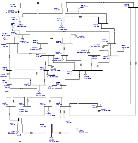
PV farms and wind mills are connected in a 30 bus sytem in which the values of the network are provided by theIEEE standards. A synchronous generator is connected to the system for the standalone operation as Figure 1 shown. The operating voltage is maintained constant at the individual bus.battery energy (IBE) is 50Jules for each node.to transmit the packet is considered as the network lifetime.
Figure 1: System Modelling
B. Modelling of PV farm:
PV farms are designed in such a way that to obtain maximum power in which MPPT techniques are used with a mechanical tracking system based on the structure of Figure 2. Each PV panel designed to be 2kW installed capacity. 20 panels are connected in series and 20 panels are connected in parallel. Thus a PV farm consist of 400 panels and produces 0.8MW of power.
1. Mathematical Modelling
A PV cell is the building block of a PV panel. A photovoltaic module is formed by connecting many cells in series and parallel. Considering only a single solar cell; it can be modeled by utilizing a current source, a diode and the resistors. This model is known as a single diode model of solar cell.
Solar cell equation for a single diode can be written as,
= − ∗ ∗ + ∗
∗ ∗ −1 −
+ ∗
ℎ
Where
= ∗ ∗ ∗ −
∗ ∗
= { + ∗( −25)}∗
Incremental conductance method uses two voltage and current sensors to sense the output voltage and current of the PV array. At MPP the slope of the PV curve is 0. This method uses the PV array's incremental conductance dI/dV to compute the sign of dP/dV. When dI/dV is equal and opposite to the value of I/V (where dP/dV =0) the algorithm knows that the maximum power point is reached and thus it terminates and returns the corresponding value of operating voltage for MPP. This method tracks rapidly changing irradiation conditions more accurately than P&O method. One complexity in this method is that it requires many sensors to operate and hence it is economically less effective
Differentiating with respect to voltage yields;
= + ( ∗ )
When the maximum power point is reached the slope
= 0
2. Modelling of Wind farm
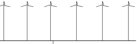
A wind mill is designed to produce 50kW of power generation. Those wind mills are constructed by vertical axis wind turbine rotors for the rooftop generation. Hence the total power generation by the wind farm is 0.2 MW. Figure 3 shows the typical structure of wind farm.
Figure 2: Typical Structure of Wind Farm
A variable speed wind turbine utilizes the available wind resource more efficiently than a fixed speed wind turbine, especially during light wind conditions. Third, the cost of the converter is low when compared with other variable speed solutions because only a fraction of the mechanical power, typically 25-30%, is fed to the grid through the converter, the rest being fed to grid directly from the stator. Thus the efficiency of the DFIG is very good for the same reason. Vertical-axis wind turbines (or VAWTs) have the main rotor shaft arranged vertically. One advantage of this arrangement is that the turbine does not need to be pointed into the wind to be effective, whichis an advantage on a site where the wind direction is highly variable.When a turbine is mounted on a rooftop the building generally redirects wind over the roof and this can double the wind speed at the turbine. If the height of a rooftop mounted turbine tower is approximately 50% of the building height it is near the optimum for maximum wind energy and minimum wind turbulence. Wind speeds within the built environment are generally much lower than at exposed rural sites, noise may be a concern and an existing structure may not adequately resist the additional stress.
III. RESULTS AND DISCUSSION
A. Power Flow Calculation:
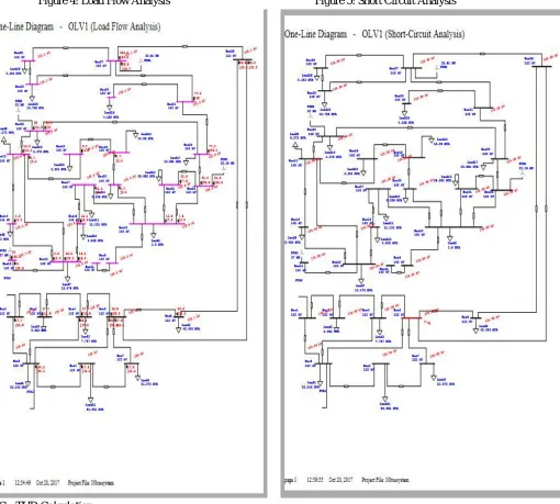
The load flow Study is capable to define and adjust the parameters of the system for each case separately. ETAP has multiple choices to define the display options based on the user’s needs and requirements from load flow analysis. Power flow is calculated in the 30 bus system using adaptive newtonraphson load flow algorithm. Here, the power factor is maintained at 0.98 and hence the voltage profile is maintained.
B. Fault Current Calculation
detection and calculation ability. Bus ID 6 is selected to be faulted and the fault current calculation is carried out by the line to ground fault and three phase fault. This fault does not affect the system tolerance. And the bus selection is based on the location and function. Here the selected bus plays a crucial role.
Figure 4: Load Flow Analysis Figure 5: Short Circuit Analysis
C. THD Calculation
D. System Performance
Table1 shows the 30 bus system performance in the case of half of the generating capacity.
Cases 50% of DG Power Factor 0.98 Fault Current 3.462 kA
THD% 0.01
Table 1: Analysis of system performance
IV. CONCLUSION
Solar energy and wind energy is variable in the nature and depends on the site. The unpredictable nature of these energy sources has its great impact on the power system operation and planning. The aim of this specific work is to evaluate the effect of the integration of solar power and wind power generator which are having opposite characteristics to each other. This aim was achieved by developing the design of hybrid PV and wind system to be implemented in standalone operation. Sizing of PV system, inverters and cables were obtained.
In order to verify the design validity, different simulation models using ETAP program have been built and carried out. Real load and solar energy data were used in the simulation to achieve more realistic results that can help for future analysis and planning processes.
Investigation of the impact of hybrid PV plant and wind plant on 30 bus system in this thesis was carried out and some analyses were established. These analyses were performed in order to verify whether the Hybrid power generation is capable to hold the planned generation plant. After those studies were performed, another analysis of the voltage stability of the whole plant was carried out. Finally, the effect of PV and wind system on the power quality at the coupling point was studied by using the harmonic analysis tools. The applied analysis has shown that the designed power plant is in good status and its voltage profile is healthy.
The standalone operation of PV and wind plant shown the ability of lessening the transient effects of buses faults. Thus represents an increased stability compared with the high transient when the PV plant is not connected. The hybrid renewable energy resource has caused the injection of some voltage harmonics that started to spread over the network. However, the amount of generated harmonics was within the international limits stated by different standards.
REFERENCES
1. Arrillaga J. Neville R. Watson[M]. Power System Harmonics. 2016 IEEE 8th International Power Electronics and Motion Control Conference (IPEMC-ECCE Asia)
2. Baohua Dong, Sohrab Asgarpoor and wei Qiao, “Voltage Analysis of Distribution Systems with DFIG Wind Turbines ,” in 2009IEEE. 3. Barker, P. P. & Mello, R. W. (2000) 'Determining the Impact of Distributed Generation on Power Systems: 1. Radial Sistribution
Systems', IEEE, 3(0), pp. 1645-1650.
4. Bhardwaj, A., Chanakya, M. & Sharma, R. K. (2013) 'Transmission System Reliability Planning', Enhanced Research Publication, 2(1), pp.
5. Breker, S., Claudi, A. & Sick, B. (2014) 'Capacity of Low-Voltage Grids for Distributed Generation: Classification by Means of Stochastic Simulations', IEEE, 30(2), pp. 689-700.
7. Dondi, P., Bayoumi, D., Haederli, C., Julian, D., and Suter, M. (2002) 'Network Integration of Distributed Power Generation', Journal ofPower Sources, 106, pp. 1-9.
8. Dulăua, L. I., Abrudean, M. &Bică, D. (2014) 'Effect of Distributed Generation on Electric Power Systems', Procedia Technology, 12(2014), pp. 683-685.
9. Eghtedarpour N, Farjah E. Power Control and Management in a Hybrid AC/DC Micro-grid[J]. IEEE Transactions on Smart Grid, 2014, 99(3):1494-1505.
10. F. Katiraei, M. R. Iravani and P. W. Lehn“Micro-Grid Autonomous Operation During and Subsequent to Islanding Process”, IEEE Transactions on Power delivery, 2005.
11. Haque, M.M. and Wolfs, P. (2016) 'A review of high PV penetrations in LV distribution networks: Present status, impacts and mitigation measures', Renewable and Sustainable Energy Reviews, 62(2016), pp. 1195-1208.
12. “IEEE Recommended Practice for Industrial and Commercial Power System Analysis”, IEEE Std. 399-1997.
13. J. T. De Oliveria, M. F. De Mederios Jr., and C. B. M. Oliveira, “Development of Modules for Transient Stability Studies of PowerSystems with Wind Turbines in Different Simulation Platforms” IEEE PES Transmission and Distribution Conference2006.
14. Kenneth, A.P. and Folly, K (2014) 'Voltage Rise Issue with High Penetration of Grid Connected PV', IFAC Proceedings Volumes, 47(3), pp. 4959–4966.
15. Kroposki B, Pink C, Basso T, et al. Microgrid Standards and Technology Development[C]// Power Engineering Society General Meeting, 2007. IEEE. IEEE, 2007:1-4.
16. Majumder R, Ghosh A, Ledwich G, et al. Load sharing and power quality enhanced operation of a distributed microgrid[J]. Renewable Power Generation Iet, 2009, 3(2):109-119.
17. Viet, N. H. and Yokoyama, A (2010) 'Impact of Fault Ride-Through Characteristics of High-Penetration Photovoltaic Generation on Transient Stability', International Conference on Power SystemTechnology, (11700577), pp. 1-7.