ABSTRACT
ANDERSON, KIM SUZANNE. Seamless Textiles with Inherent Shape. (Under the direction of Abdelfattah Seyam.)
Currently, the cutting and sewing process is utilized to produce woven products with tailored shape. Unfortunately, there are a number of adverse consequences caused from seams. The goal of this research was to investigate new methods in which a shaped seamless woven product could be produced using current technology.
After a thorough review of the literature, two sets of weaving trials were conducted. In the first set of trials three variables were investigated, specifically 1) different pick densities, 2) different weave constructions and 3) yarns with different degrees of shrinkage. Each variable was manipulated to produce differential shrinkage during the fabric finishing process. In addition, the three variables were utilized in
different combinations within a tubular construction in an effort to create inherent shape.
The second set of weaving trials were undertaken to investigate the correlation between fabric width shrinkage and a given set of fabric construction parameters in order to create inherent shape within the fabric. Establishing a reliable correlation between fabric width shrinkage and a given set of parameters could lead to the design and development of fabrics with many different shapes. It was of additional interest to investigate the ability to design shaped fabrics with similar finished fabric tightness. The same set of parameters utilized in the first set of weaving trials were examined in the second set of weaving trials.
A statistical analysis was performed using the results from the second set of weaving trials. The analysis was performed to examine the success of the overall
experiment by assessing the contribution each of the three independent variables made to the resulting finished width shrinkage, as well as finished fabric tightness. In addition, the contributions made by the interactions between different combinations of the
In order for seamless shaped woven fabrics to be produced without performing additional weaving trials, a predictive model was created. The predictive model would allow a designer to utilize the data generated in the second set of weaving trials to estimate the width shrinkage of a given combination variables. This knowledge would enable a designer to create different shapes by utilizing different combinations of the three variables investigated in this study to produce a specific width shrinkage.
In order to assess the potential for a speedy adoption of a seamless woven textile with inherent shape, an economic feasibility study was completed. Everett Roger’s Model of the Innovation-Decision Process was used as a paradigm to aid in the investigation of the economic potential of a seamless shaped textile. Other important economic issues pertaining to a new successful product adoption were addressed, including cannibalism, manufacturing strategies and marketing opportunities.
Utilizing the proposed experimental methods led to a variety of fabrics with inherent shape. A correlation between fabric width shrinkage and a given set of fabric construction parameters was established. The methods developed in this study could be utilized to produce many different fabrics with inherent shape that might be used in a wide variety of applications.
SEAMLESS TEXTILES
WITH INHERENT SHAPE
by Kim Anderson
A dissertation submitted to the Graduate Faculty of North Carolina State University
in partial fulfillment for the Degree of Doctor of Philosophy
Textile Technology Management Raleigh, NC
2004 Approved By:
___________________ _____________________ ______________________ Dr. Abdelfattah Seyam Dr. Martin King Dr. Benham Pourdeyhimi
CHAIR
BIOGRAPHY
Kim Anderson entered North Carolina State University in 1987 and received a Bachelor of Science in Textiles with a Concentration in Design in 1990. Upon
ACKNOWLEDGEMENTS
I would like to thank the five professors on my committee-Dr. Abdelfattah Seyam, Dr. Martin King, Dr. Benham Pourdeyhimi, Dr. George Hodge and Dr. Nancy Cassill for their contribution to this project. Special thanks to Dr. Seyam for providing much appreciated guidance and expertise throughout the project.
Special thanks to Derek Gun of Unifi Incorporated for donating yarn and for his helpful expertise in yarn shrinkage.
Many thanks to William Barefoot for his many hours spent adjusting and refining the weaving equipment, upon which this project depended.
TABLE OF CONTENTS
LIST OF TABLES……….………xi
LIST OF FIGURES………..xiv
LIST OF FORMULAS….………xix
PART I: INTRODUCTION………..…1
1.0 INTRODUCTION………...2
PART II: LITERATURE REVIEW……….……...5
2.0 INTRODUCTION………...6
2.1 CURRENT METHODS FOR PRODUCING A SEAMLESS WOVEN TEXTILE PRODUCT WITH INHERENT SHAPE……….…………6
2.1.1 THE FORMATION OF A SHAPED TUBE BY CUTTING SPECIFIED WARP YARNS TO A PREDETERMINED LENGTH……….……...6
2.1.2 FORMING A SHAPED PROSTHESIS USING A NARROW WIDTH MULTI-SHUTTLE LOOM……….………..8
2.1.3 USING A STRAIGHT TUBE AND THE CUT AND SEW PROCESS TO PRODUCE A SHAPED PROSTHESIS SUITABLE FOR THE ASCENDING AORTA……….…….9
2.1.4 ANOTHER METHOD FOR PRODUCING A SHAPED PROSTHESIS BY UTILIZING A STRAIGHT TUBE AND THE CUT AND SEW PROCESS ……….……….…..10
2.1.5 FORMING A SHAPED TUBE BY ENGAGING AND DISENGAGING SPECIFIED WARP YARNS………12
2.1.6 WOVEN THREE DIMENSIONAL SHAPES PRODUCED DIRECTLY FROM A LOOM………...…….…..15
2.1.7 PRODUCING SEAMLESS SHAPED AIRBAGS………17
2.1.9 UTILIZING AN ADJUSTABLE REED TO PRODUCE
A SEAMLESS SHAPED TEXTILE………..………...21
2.1.10 UTILIZING A FAN REED TO FORM A SHAPED TUBE………...22
2.1.11 HERMENEUTIC APPROACH TO A SEAMLESS TUNIC………25
2.2 OTHER FABRIC FORMING PROCESSES IN WHICH A TEXTILE PRODUCT WITH INHERENT SHAPE CAN BE PRODUCED………..27
2.2.1 SHAPED KNITTING………27
2.2.2 BRAIDING………29
2.2.2.1 TWO-DIMENSIONAL BRAIDING………...29
2.2.2.2 THREE DIMENSIONAL BRAIDING………...30
2.3 CONCLUSION………...30
2.4 WORKS CITED………33
PART III: TRIALS EXECUTED ON THE MULLER LN 59317A AND THE AVL INDUSTRIAL DOBBY WEAVINGMACHINES………...37
3.0 INTRODUCTION……….38
3.1 TRIALS CONDUCTED ON THE MULLER LN 59317A……….. 38
3.1.1 EXPERIMENTAL PROCEDURE………39
3.1.1.1 MATERIALS……….39
3.1.1.2 WEAVE DESIGNS………...39
3.1.1.3 WEFT THREAD DENSITIES………..40
3.1.1.4 FABRIC FORMATION………40
3.1.1.5 FABIC FINISHING………...………41
3.1.1.6 EVALUATION………..42
3.1.2 RESULTS AND DISCUSSION………43
3.1.2.2 UTILIZING DIFFERENT WEFT YARN DENSITIES
AND DIFFERENT WEAVE DESIGNS………...45
3.1.2.3 UTILIZING DIFFERENT WEFT YARN DENSITIES AND WEFT YARNS WITH DIFFERENT DEGREES OF SHRINKAGE………48
3.1.2.4 UTILIZING DIFFERENT WEFT YARN DENSITIES, DIFFERENT WEAVE DESIGNS, AND WEFT YARNS WITH DIFFERENT DEGREES OF SHRINKAGE...……….………51
3.2 TRIALS CONDUCTED ON THE AVL INDUSTRIAL DOBBY………...52
3.2.1 EXPERIMENTAL PROCEDURE………52
3.2.1.1 MATERIALS………52
3.2.1.2 WEAVE DESIGNS………...53
3.2.1.3 WEFT THREAD DENSITIES………..53
3.2.1.4 FABRIC FORMATION………53
3.2.1.5 FABRIC FINISHING………....55
3.2.1.6 EVALUATION………..55
3.2.2 RESULTS AND DISCUSSION………55
3.3 CONCLUSION………. 60
3.4 WORKS CITED………61
PART IV: INFLUENCE OF CONSTRUCTION PARAMETERS ON FABRIC WIDTH SHRINKAGE……….62
4.0 INTRODUCTION……….63
4.1 EXPERIMENTAL DESIGN……….64
4.1.1 MATERIALS……….64
4.1.1.1 WEFT AND WARP YARNS………64
4.1.2.1 SHRINKAGE TESTS………....65
4.1.3 WEAVE DESIGNS………...67
4.1.4 WEFT THREAD DENSITIES………..67
4.1.5 FABRIC FORMATION………67
4.1.6 FABRIC FINISHING………68
4.1.7 EVALUATION………...68
4.1.7.1 EVALUATION OF THE PERCENT SHRINKAGE OF WIDTH, LENGTH AND AREA………...68
4.1.7.2 OFF-LOOM AND FINISHED THREAD DENSITY …………..70
4.1.7.3 FINISHED WARP AND FILLING COVER AND COVER FACTOR. ……….………71
4.1.7.4 RUSSELL’S TIGHTNESS FACTOR………...74
4.1.7.5 STAISTICAL MODELS………...77
4.2 RESULTS………..79
4.2.1 YARN SHRINKAGE TESTS………...………...…….80
4.2.1.1 SHRINKAGE RESULTS OBTAINED FROM THE LESSONA METHOD………...80
4.2.1.2 SHRINKAGE RESULTS OBTAINED FROM THE ASTM 4031-95a METHOD………..81
4.2.1.3 SHRINKAGE RESULTS OBTAINED FROM THE HAMBY RESEARCH LABORATORY: BOIL AND DRY HEAT METHOD……….………..……82
4.2.3 THE EVALUATION OF THE YARN SHRINKAGE
BEHAVIOR OF THE THREE DIFFERENT WEFT YARNS IN TERMS OF FINISHED FABRIC TIGHTNESS AND
FINISHED WIDTH SHRINKAGE……….………..……...87 4.2.4 RESULTS OBTAINED FROM THE EVALUATION OF
FINISHED FABRIC TIGHTNESS WITH RESPECT TO FINISHED WIDTH SHRINKAGE AND ON-LOOM FABRIC
TIGHTNESS………90 4.2.4.1 THE FINISHED FABRIC TIGHTNESS AND
WIDTH SHRINKAGE RESULTING FROM A SPECIFIC WEAVE AND THREE DIFFERENT
WEFT YARNS………..………..92 4.2.4.2 DERIVATION OF THE THEORETICAL
MAXIMUM COVER FACTOR..………...95 4.2.4.3 THE FINISHED FABRIC TIGHTNESS AND WIDTH
SHRINKAGE RESULTING FROM A SPECIFIC WEAVE AND THREE DIFFERENT WEFT
YARNS WITH POINTS EXCLUDED………...………....100 4.2.4.4 INVESTIGATING THE INTERACTION BETWEEN
FABRIC SAMPLES CONSTRUCTED WITH DIFFERENT
SETS OF PARAMETERS………..103
4.2.3.5 PRODUCING SPECIFIC FINISHED FABRIC TIGHTNESS FROM A GIVEN SET OF PARAMETERS…………..……...106 4.2.3.6 THE FINISHED FABRIC TIGHTNESS AND FINISHED
WIDTH SHRINKAGE RESULTING FROM THE FOUR
DIFFERENT WEAVES……….……….108
4.2.4.7 THE FINISHED FABRIC TIGHTNESS RESULTING FROM A SPECIFIC ON-LOOM FABRIC TIGHTNESS……….…….111 4.3 STATISTICAL MODELS……….…..120
4.3.1 EVALUATION OF EXPERIMENT……….…..121 4.3.2 STAITICAL MODEL DEVELOPED TO PREDICT
4.5 WORKS CITED………..129
PART V: EVALUATION OF THE ECONOMIC FEASIBILITY OF A SEAMLESS WOVEN PRODUCT WITH INHERENT SHAPE………..131
5.0 INTRODUCTION……….…..132
5.1 EVALUATING THE ECONOMIC FEASIBILITY OF A NEW PRODUCT AND ITS MARKET……….…...132
5.1.1 ROGERS’ MODEL: DIFFUSION OF INNOVATION…………..……132
5.1.2 SUCCESSFUL DIFFUSION OF THE INNOVATION: A SEAMLESS WOVEN PRODUCT WITH INHERENT SHAPE……….….…..138
5.1.2.1 RELATIVE ADVANTAGE………139
5.1.2.2 COMPATIBILITY………..140
5.1.2.3 COMPLEXITY………141
5.1.2.4 TRIALABILITY………..141
5.1.2.5 OBSERVABILITY………..142
5.2 EXPERT’S OPINIONS TO FURTHER VALIDATE THE SUCCESSFUL ADOPTION OF A SEAMLESS SHAPED WOVEN PRODUCT WITH INTENDED FOR A MEDICAL APPLICATION………...…..144
5.2.1 ASSESSING THE POTENTIAL FOR THE INNOVATION TO HAVE A RELATIVE ADVANTAGE, COMPATIBILITY AND OBSERVABILITY: BRENT FOLWER………..145
5.2.2 ASSESSING THE POTENTIAL FOR THE INNOVATION TO HAVE A RELATIVE ADVANTAGE, COMPATIBILITY AND OBSERVABILITY: MAC RITCHIE………..……….148
5.2.3 ASSESSING THE INNOVATION IN TERMS OF COMPLEXIBILITY AND TRIALABILITY: JOHN TAWS……..……149
5.3 BUSINESS ISSUES RELATED TO SEAMLESS TECHNOLOGY………….…..152
5.3.2 INVESTIGATING THE POTENTIAL FOR CANNIBALIZATION WITH THE INTRODUCTION OF A SHAPED SEAMLESS
PRODUCT………..………155
5.3.3 MANUFACTURING STRATEGY FOR A SHAPED SEAMLESS PRODUCT………...157
5.3.3.1 MACHINERY……….…157
5.3.3.2 LABOR AND CAPITAL INVESTMENT………..…158
5.3.3.3 INTEGRATED MANUFACTURING PROCESSES………...159
5.4 MARKETING OPPORTUNITIES………..…160
5.4.1 FASHION APPAREL……….…160
5.4.2 PROTECTIVE CLOTHING………....163
5.4.3 MEDICAL APPLICATIONS………..164
5.4.4 AUTOMOTIVE, AEROSPACE AND INDUSTRIAL PRODUCTS………...164
5.5 CONCLUSION………165
5.6 WORKS CITED………..167
PART VI: SUMMARY AND FUTURE RESEARCH 6.0 SUMMARY AND FUTURE WORK……….171
6.1 WORKS CITED………..175
PART VII: APPENDICES 7.1 APPENDIX A……….…178
LIST OF TABLES
PART III: TRIALS EXECUTED ON THE MULLER LS 59317A AND THE AVL INDUSTRIAL DOBBY WEAVING MACHINES
Table 3.1 Maximum and Minimum Pick Density for the Filling Yarns of Each Weave Design Woven on Muller
Weaving Machine ……….... 40
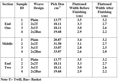
Table 3.2 Weave Design, Weft Yarn Density, and Flattened Width Dimensions Before and After Finishing of Samples 1, 2, 3 and 4……… 44
Table 3.3 Width Shrinkage of the End and Middle Sections and D* of Samples 1, 2, 3 and 4………...…….……….45
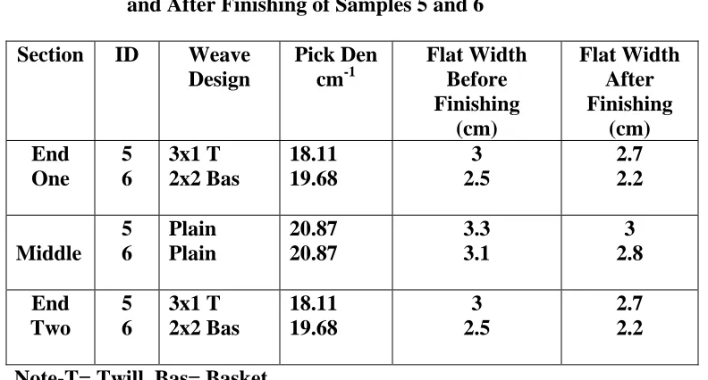
Table 3.4 Weave Design, Weft Yarn Density, and Flattened Width Dimensions Before and After Finishing of Samples 5 and 6……… 46
Table 3.5 Results from the ASTM D 2259-02 Yarn Shrinkage Tests…………...…48
Table 3.6 First Pick Pattern Repeat………54
Table 3.7 Second Pick Pattern Repeat………...54
Table 3.8 Results from the ASTM D 2259-02 Shrinkage Test………..56
Table 3.9 Section, Finished Width Dimensions and Percent Shrinkage of Samples 1B and 2B Woven with the First Repeat Pattern………57
PART IV: TRIALS EXECUTED ON THE PICANOL GTM WEAVING MACHINE Table 4.1 Fiber Type, Yarn Type, Packing Factor and Fiber Density of Each Yarn Used in the Experiment……….……….75
Table 4.2 Weave Factor of each of the Four Weave Designs ….………..76
Table 4.3 Results from the Leesona Skein Shrinkage Test………....81
Table 4.4 Shrinkage Results From the ASTM 4031-95a………...82
Table 4.6 Calculated Maximum Warp and Filling Cover and Cover
Factors………....98 Table 4.7 The Correlation Coefficients Between On-loom Fabric Tightness and
Finished Fabric Tightness for the Fabrics Constructed with
Each of the Three Weft Yarns……….115 Table 4.8 The Correlation Coefficients Between On-loom Fabric Tightness and
Finished Fabric Tightness for the Fabrics Constructed with
Each of the Four Weave Designs………117 PART V: EVALUATION OF THE ECONOMIC FEASIBILITY OF A SEAMLESS
WOVEN PRODUCT WITH SINHERENT SHAPE Table 5.1 Summary Table: Evaluating a Seamless Shaped Product
in Relation to Roger’s Five Components of the Persuasion Stage……..145 APPENDIX A
Table 3.1A Samples Woven on the Muller Weaving Machine Utilizing Different Weave Designs, Different Pick
Densities and Weft Yarns With Differential Shrinkage………..179 APPENDIX B
Table 4.1B Detail of Trials Woven on the Picanol GTMLoom………181 .
Table 4.12B Correlation Coefficient for the On-Loom and Finished Fabric
Tightness of the Fabrics Constructed with the Three Weft Yarns……...214 Table 4.13B Correlation Coefficient for On-Loom and Finished Fabric
Tightness of the Fabrics constructed with the Four Weave
Designs……….216 Table 4.14B Analysis of Variance Table with Respect to Finished Fabric
Tightness Reduced Data Set………..……….…….218 Table 4.15B Analysis of Variance Table with Respect to Finished Width
LIST OF FIGURES PART II: LITERATURE REVIEW
Figure 2.1 Tapered Cylinder, Mandrel, Oven and Finished Sleeve………...………...7
Figure 2.2 Example of a Bifurcated Prosthesis……….8
Figure 2.3 A Shaped Aorta Prosthesis Created From Cutting and Sewing………...…………9
Figure 2.4 Gelweave ValsalvaTM produced by Vascutek…...……….….……...11
Figure 2.5 A-Straight Tube, B-Cut Tube, C-Sutured Tube to Create Taper ……….….…………12
Figure 2.6 Process of Disengaging Warp Yarns ………..……..13
Figure 2.7 Examples of Tapered Shapes ……….……….…..13
Figure 2.8 Illustration of a Bifurcated and Trifurcated Graft……….………14
Figure 2.9 Disengaged Warp Ends ……….……...15
Figure 2.10 Dome Shapes ……….…………...16
Figure 2.11 Seamless Woven Air Bag ……….………18
Figure 2.12 Gathers Created by Utilizing Non-Elastic and Elastic Yarns…...……….19
Figure 2.13 Gathers Created by Utilizing Non-Elastic and Elastic Yarns……….…...20
Figure 2.14 Sketch of Shaped Dress, Unfinished Dress, Dress After Six Hand Washings………..…..21
Figure 2.15 Diagram of a Single Fan-Shaped Reed ……….23
Figure 2.16 Multiple Fan-Shaped Reed....………....23
Figure 2.17 Representation of the Principle of Warp Displacement………...23
Figure 2.18 Examples of Tubular Shapes Produced on a Shuttle Loom Equipped With a Fan-Shaped Reed………...24
Figure 2.20 Shoulder and Neck Opening ……….26 PART III: TRIALS EXECUTED ON THE MULLER LS 59317A AND THE AVL
INDUSTRIAL DOBBY WEAVING MACHINES
Figure 3.1 Double Cloth Weave Designs Used in Set One……….40 Figure 3.2 Tubular Design of Set One Woven on the Muller Loom………...41 Figure 3.3 Photograph of Sample 6 Along with Filling Yarn, Weave,
On-loom Pick Density, and Flattened Width Dimensions
(After Finishing) of Each Section………..47 Figure 3.4 Photograph of Samples 1A, 2A & 3A Along with Filling
Yarn, Weave, On-Loom Pick Density and Flattened Width
Dimensions (After Finishing) of Each Section………..50 Figure 3.5 Photographs of Samples 5A & 6A Along with Filling Yarn,
Weave, On-Loom Pick Density and Flattened Width Dimensions
(After Finishing) of Each Section………..51 Figure 3.6 Double Cloth Weave Designs Used in Set Two………....53 Figure 3.7 Photograph of Tubular Sample 1B and the Relationship Between
Percentage of the Number of High Shrink Filling Yarn and Percentage of Width Shrinkage of Each Section, Weave Design: 4x4 Twill,
On-loom Filling Yarn Density: 10.63 picks/cm………58 Figure 3.8 Photograph of Tubular Sample 3B and the Relationship Between
Percentage of the Number of High Shrink Filling Yarn and Percentage of Width Shrinkage of Each Section,
Weave Design: 4x4 Twill, On-loom Filling Yarn Density:
10.63 picks/cm………..59 PART IV: TRIALS EXECUTED ON THE PICANOL GTM WEAVING
MACHINE
Figure 4.1 Double Cloth Weave Designs………...67 Figure 4.2 Crimp Contraction Versus Finished Width Shrinkage
(Plain Weave)………84
Figure 4.3 Crimp Contraction Versus Finished Width Shrinkage
Figure 4.4 Crimp Contraction Versus Finished Width Shrinkage
(8-H Sateen Weave)………...…85
Figure 4.5 Crimp Contraction Versus Finished Width Shrinkage
(4x4 Basket Weave)………..….85
Figure 4.6 Finished Fabric Tightness Versus Finished Width Shrinkage
(Plain Weave)……….……….…...88 Figure 4.7 Finished Fabric Tightness Versus Finished Width Shrinkage
(3x1Twill Weave)……….….…89 Figure 4.8 Finished Fabric Tightness Versus Finished Width Shrinkage
(8-H Sateen Weave)………..….89 Figure 4.9 Finished Fabric Tightness Versus Finished Width Shrinkage
(4x4 Basket Weave)………...90 Figure 4.10 Horizontal Wrinkling of Samples 1, 31 and 61……….93 Figure 4.11 Finished Fabrics Constructed With the First Four Loosest Pick
Densities, Specifically 62, 63 and 64………94 Figure 4.12 Cross Section of the Warp Yarns in a Fabric Before Finishing....………95 Figure 4.13 Cross Section of the Warp Yarns in a Fabric in a Jammed
Condition After Finishing……….,96 Figure 4.14 Finished Fabric Tightness Versus Finished Width Shrinkage
(Plain Weave)……….……….….100 Figure 4.15 Finished Fabric Tightness Versus Finished Width Shrinkage
(3x1Twill Weave)……….…...101 Figure 4.16 Finished Fabric Tightness Versus Finished Width Shrinkage
(8-H Sateen Weave)……….101 Figure 4.17 Finished Fabric Tightness Versus Finished Width Shrinkage
(4x4 Basket Weave)……….102 Figure 4.18 Finished Fabric Tightness Versus Finished Width Shrinkage
of Five Width Dimensions………...104 Figure 4.19 Finished Fabric Tightness Versus Finished Width Shrinkage
Figure 4.20 Finished Fabric Tightness Versus Finished Width Shrinkage
of Five Width Dimensions (8-H Sateen Weave)……….105 Figure 4.21 Finished Fabric Tightness Versus Finished Width Shrinkage
of Five Width Dimensions (4x4 Basket Weave)………...105 Figure 4.22 Finished Fabric Tightness Versus Finished Width
Shrinkage of Four Different Weaves Constructed
with ULS Weft Yarn………107 Figure 4.23 Finished Fabric Tightness Versus Finished Width
Shrinkage of Four Different Weaves Constructed
with PET Weft Yarn………108 Figure 4.24 Finished Fabric Tightness Versus Finished Width
Shrinkage of Four Different Weaves Constructed
with Type 400 Weft Yarn………108 Figure 4.25 On-Loom Fabric Tightness Versus Finished Width Fabric
Tightness of the Four Different Weaves Constructed
with ULS Weft Yarn………111 Figure 4.26 On-Loom Fabric Tightness Versus Finished Fabric
Tightness of the Four Different Weaves Constructed
with PET Weft Yarn………112 Figure 4.27 On-Loom Fabric Tightness Versus Finished Fabric
Tightness of the Four Different Weaves Constructed
with Type 400 Weft Yarn ...………112 Figure 4.28 On-Loom Fabric Tightness Versus Finished Width Fabric
Tightness of the Four Different Weaves Constructed
with ULS Weft Yarn………113 Figure 4.29 On-Loom Fabric Tightness Versus Finished Fabric
Tightness of the Four Different Weaves Constructed
with PET Weft Yarn………114 Figure 4.30 On-Loom Fabric Tightness Versus Finished Fabric
Tightness of the Four Different Weaves Constructed
Figure 4.31 Finished Fabric Tightness Versus On-Loom Fabric Tightness
(Plain Weave)………...117
Figure 4.32 Finished Fabric Tightness Versus On-Loom Fabric Tightness (3x1 Twill Weave)……….……….118
Figure 4.33 Finished Fabric Tightness Versus On-Loom Fabric Tightness (8-Harness Sateen Weave)……….………….118
Figure 4.34 Finished Fabric Tightness Versus On-Loom Fabric Tightness (4x4 Basket Weave)……….119
PART V: EVALUATION OF THE ECONOMIC FEASIBILITY OF A SEAMLESS WOVEN PRODUCT WITH SINHERENT SHAPE Figure 5.1 A Model of the Stages in the Innovation-Decision Process………134
Figure 5.2 Longitudinal Section of the Aortic Valve………...146
Figure 5.3 Normal Case of Cannibalization………...……...153
Figure 5.4 Abnormal Case of Cannibalization………..154
Figure 5.5 Examples of Different Pattern Shapes……….161
Figure 5.6 Examples of Standard Pant and a Dress Design…………..………162
Figure 5.7 A Bifurcated Prostheses………...162
APPENDIX B Figure 4.1B Maximum Weavability Curve of an 8-Harness Weave ULS Weft Yarn………227
LIST OF FORMULAS
PART III: TRIALS EXECUTED ON THE MULLER LS 59317A AND THE AVL INDUSTRIAL DOBBY WEAVING MACHINES
Formula 3.1 Percentage of Fabric Width Shrinkage……….……….42
Formula 3.2 Percent Difference Between the Width of the End Sections and the Width of the Middle Section………..………42
Formula 3.3 Percent Shrinkage of the Fabric Width………..55
PART IV: TRIALS EXECUTED ON THE PICANOL GTM WEAVING MACHINE Formula 4.1 Percent Yarn Shrinkage……….66
Formula 4.2 Percent Width Shrinkage Off-Loom (Grey)………….……….68
Formula 4.3 Percent Width Shrinkage After Finishing………..69
Formula 4.4 Percent Length Shrinkage Off-Loom (Grey)……….69
Formula 4.5 Percent Length Shrinkage After Finishing………69
Formula 4.6 Percent Area Shrinkage Off-Loom (Grey)………69
Formula 4.7 Percent Area Shrinkage After Finishing………70
Formula 4.8 Off-Loom Pick Density………..70
Formula 4.9 Finished Pick Density………70
Formula 4.10 Finished Warp Cover and Cover Factor………71
Formula 4.11 Finished Weft Cover and Cover Factor……….72
Formula 4.12 Maximum Warp Cover and Cover Factor……….72
Formula 4.13 Maximum Weft Cover and Cover Factor………..73
Formula 4.14 General Weavability-Limit Relationship………...73
Formula 4.15 Yarn Diameter………74
PART 1:
1.0 INTRODUCTION
In today’s volatile global market it has become increasingly difficult for textile mills and apparel manufacturing companies to maintain a competitive advantage. United States textile companies are no longer able to sustain a competitive advantage over their competitors by focusing on cost and quality alone. It is paramount that textile companies think of revolutionary new methods to produce innovative products. To be globally competitive, textile companies should offer products that can not be bought anywhere else. One area with great potential is the production of seamless woven products that have inherent shape. There are many benefits to producing a seamless shaped woven product, as well as numerous new products that could be utilized in a wide variety of markets.
Historically, when a woven product with a tailored shape was needed, cutting and sewing was required. Unfortunately, there are a number of adverse consequences caused from utilizing seams in a woven textile product. First, the process of cutting and sewing is the most labor intensive step in the formation of a product. Second, there is a
concentration of stress where the seams are located which jeopardizes performance properties and ultimately results in premature product failure. Third, cutting and sewing is done manually which introduces the potential for human error. Fourth, the sewing process can create needle holes in the fabric as well as damage the yarn. Fifth, fabric scraps produced from the cut and sew process are discarded, resulting in fabric waste. In addition, seams in a garment create a bulkiness especially at the shoulders and underarms which can effect the comfort.
After a thorough review of the literature, two sets of weaving trials were undertaken in order to create shape in a woven structure without cutting or sewing or using any seams of any type. In the first set of trials detailed in Part III, three variables were utilized within a tubular construction, specifically 1) different pick densities, 2) various weave constructions and 3) yarns with differential shrinkage. These variables could potentially be manipulated to cause different amounts of shrinkage within the fabric structure. Most textile fabrics are designed to have minimal shrinkage as well as uniform shrinkage. At the beginning of the design process fabric construction variables are carefully chosen to produce minimum and uniform shrinkage. However, in this study these variables were manipulated to create shape by producing differential shrinkage within the fabric during the finishing process.
The main goal of the second set of weaving trials detailed in Part IV, was to investigate the correlation between fabric width shrinkage and a given set of fabric construction parameters in order to create inherent shape within the fabric. It was of additional interest to investigate the ability to design shaped fabrics that would result in the same or similar finished fabric tightness.
After analyzing the results obtained from Part IV, two statistical models were performed. The first statistical model was utilized to determine the contribution each of the three variables, as well as different combinations of the three variables had on the finished width shrinkage and finished fabric tightness. The second statistical model was a predictive model that was performed in an attempt to enable a designer to produce a variety of different shapes, given a specific combination of the three variables analyzed in this research.
In Part V an economic study was conducted in order to assess the potential for a successful adoption of a seamless woven product with inherent shape. A seamless
At the persuasion stage the potential adopter establishes either an unfavorable or favorable attitude towards the innovation. The attitude towards the innovation determines whether the potential adopter will either accept or reject the innovation.
Other important economic issues pertaining to a new successful product adoption were addressed, including cannibalism, manufacturing strategies and marketing
opportunities. Cannibalism is defined as the process by which a new product gains sales by diverting them from an existing product. Although this research is by no means all inclusive, the issues raised are pertinent and could facilitate a successful adoption of a new product.
PART II:
2.0 INTRODUCTION
Historically, when a seamless shaped textile product was needed, cutting and sewing was required. There are a number of adverse consequences caused from utilizing seams in a textile product. First, the process of cutting and sewing is the most labor intensive step in the formation of a product. Second, the sewing process can also create needle holes in the fabric as well as damage the fiber within the yarn. The presence of needle holes and damaged fibers could adversely affect the strength and performance of the fabric. Third, there is a concentration of stress where the seams are located which jeopardizes performance properties and ultimately results in premature product failure. Fourth, cutting and sewing is done manually which introduces the potentail for human error. In addition, fabric waste is generated by the cut and sew process and seams in a garment create a bulkiness especially at the shoulders and underarms which can affect the comfort of a garment.
There have been a number of successful attempts to produce a seamless textile product that has an inherent shape in which cutting and sewing is not required.
Unfortunately, the majority of these methods have limitations. The current methods have either limited production speeds; require specialized equipment; still require a manual processing stage; produce fabric that has either structural limitations or inappropriate physical properties for a variety of end uses. The current methods that have been utilized to produce seamless textile products with inherent shape will be detailed in the following text.
2.1 CURRENT METHODS FOR PRODUCING A SEAMLESS WOVEN
TEXTILE PRODUCT WITH INHERENT SHAPE
2.1.1 THE FORMATION OF A SHAPED TUBE BY CUTTING
SPECIFIED WARP YARNS TO A PREDETERMINED LENGTH
weaving, a selected number of the warp yarns are cut shorter than the full length of the other warp ends. The number of yarns cut and the length of the yarn determines the degree of taper. Warp yarns that are not the full length of the original warp are terminated at specified lengths to form a tapered sleeve (LaPointe, et al., 1987.).
After the sleeve is woven it is placed on a conforming supportive mandrel. The sleeve can be shrunk thermally or chemically. A thermal shrinkage entails placing the woven structure on a mandrel and placing the mandrel in an oven at elevated
temperatures, (refer to Figure 2.1). Chemical shrinkage involves wetting the sleeve with methylene chloride at room temperature and allowing it to shrink on the mandrel
(LaPointe et al.,1987).
Figure 2.1 Tapered Cylinder, Mandrel, Oven and Finished Sleeve (LaPointe et al., 1987)
2.1.2 FORMING A SHAPED ARTERIAL PROSTHESIS USING A NARROW WIDTH MULTI-SHUTTLE LOOM
In 1952 a researcher named Voorhees observed a silk suture hanging free in the heart. The suture had become coated with endothelial cells (Callow, 1986). These cells line arteries and prevent blood from clotting (Moreland, 1997). From this observation he surmised that a fabric graft might do the same and avoid clotting. A tube made from sail cloth proved his theory correct and began what is now known as arterial reconstructive surgery (Callow, 1986). Today, polyester textile prostheses are produced in a wide range of sizes, fabric types and configurations by a number of manufacturers.
Historically, a woven tube with a consistent diameter throughout the length has been used to replace a diseased or damaged lumen in the body. A woven tube is basically a tubular fabric with a consistent width. Tubular fabrics are essentially 2D woven fabrics that are joined at the edges to make a tubular product. When a shuttle loom is used the fill yarn loops circumferentially from the bottom layer to the top layer forming a seamless tube with excellent strength (Clarke, 2000). A prosthesis can also be produced in a seamless bifurcated shape. A bifurcated shape refers to a tube that separates into two branches, see Figure 2.2. A narrow width shuttle loom with multiple shuttles is utilized to form a bifurcated tube. One large tube is initially woven with one shuttle, at a given point two shuttles begin weaving simultaneously to form two tubes (Taws, 2003). These seamless shaped products have been used primarily as abdominal prostheses.
2.1.3 USING A STRAIGHT TUBE AND THE CUT AND SEW PROCESS TO PRODUCE A SHAPED PROSTHESIS SUITABLE FOR THE ASCENDING AORTA
Tubular fabrics have been used to replace or repair damaged or diseased lumens in the body for half a century. In situations where a tube with a tailored shape is needed, cutting and sewing is required. In specific locations such as the ascending aorta a prosthesis with a tailored shape is desirable. The aortic valve pumps blood into the ascending aorta. The blood then goes on through the systemic circulatory system (Guyton, 1974).
The aortic valve consists of three leaflets and three sinuses. The leaflets are mobile parts of the valve and the sinuses are cavities. At the point at which the aorta meets the aortic valve there is a slight tear-shaped bulge. When the ascending aorta becomes diseased it is desirable for the prosthesis to mimic the shape of the human aorta. The straight ascending aortic tubular grafts available at present do not allow the proper preservation of the natural aortic valve. The straight tube prohibits the leaflets from fluttering free. Through time the leaflets in the aortic valve are worn down (Fowler, 2003). For every person the dimensions of the tear-shaped bulge and the diameter of the tube vary slightly (Thubrikar, 2002).
Attempts to imitate the tear shaped bulge of the ascending aorta have been made by utilizing a straight tube and sewing three separate pieces of fabric to one end of the tube, see Figure 2.3.
The utilization of the shaped prosthesis created by cutting and sewing is new, therefore information concerning the long-term performance is somewhat limited.
However, the production of the prosthesis is manual therefore, subject to human error and labor intensive. Some of the problems attributed to human error are leakage caused from needle holes in the prosthesis. In addition, the thread that is used to sew the prosthesis together is a continuous filament yarn. If the yarn crimps during sewing it can break, resulting in additional labor time and possibly defects (Fowler, 2003).
Another drawback to cutting and sewing is the time it takes to produce the prosthesis. The prosthesis is produced in the operating room right before surgery. It takes approximately thirty minutes to cut and sew one prosthesis. In every operating room there exists a sterile environment. Although thirty minutes may not seem to be an ordinate amount of time, sterile time is costly. The time it takes to cut and sew the prosthesis is valuable time lost by the surgeons who are unable to begin surgery until the prosthesis is complete (Fowler, 2003).
2.1.4 ANOTHER METHOD FOR PRODUCING A SHAPED
PROSTHESIS BY UTILIZING A STRAIGHT TUBE AND THE CUT AND SEW PROCESS
Figure 2.4 Gelweave ValsalvaTM produced by Vascutek (Vascutek Ltd., 2003)
The Gelweave ValsalvaTM consists of three distinct parts, a body, a skirt and a collar. The skirt and collar are hand sewn onto the body. The skirt is sited between the body and the collar of the graft. It is designed to provide compliance in a horizontal plane and recreate the anatomy of the sinuses within the aortic valve. The special design of the product allows for smooth closing of the aortic valve leaflets, superior to that obtained with standard cylindrical grafts (Vascutek Ltd, 2003).
Although the Gelweave ValsalvaTM prosthetic graft produced by Vascutek Ltd. is
a great improvement over a straight tube, the collar and skirt need to be cut and sewn onto the body of the tube. The production of the graft is very labor intensive and
expensive. The total production time of one graft is approximately one and half days. In addition the cut and sew process is executed by humans, therefore there is always a potential for human error (Ritchie, 2004).
Body
2.1.5 FORMING A SHAPED TUBE BY ENGAGING AND DISENGAGING SPECIFIED WARP YARNS
A seamless tubular product with gradual changes in the diameter along the length of the tube can be produced by changing the number of warp yarns during weaving. This particular method of forming a tailored-shaped tube has been utilized in medical applications, specifically where a gradual narrowing of the prosthesis at the ends is desired. When a vascular prosthesis is implanted into the body it is paramount that the external diameter of the textile tube matches the internal diameter of the body lumen very closely. The close fit allows the tube to conform to the internal surface of the body lumen. (Nunez, and Schmitt, 1999). Prior to this invention, if a diseased vessel changed from one diameter to a second diameter, the surgeon would compensate for the diameter change by cutting the straight seamless woven graft along the length, see A & B in Figure 2.5. The cut edges were then sutured back together to create a gradual diameter change at the end of the graft, see C in Figure 2.5 (Nunez, and Schmitt, 1999).
Figure 2.5 A-Straight Tube, B-Cut Tube, C-Sutured Tube to Create Taper (Nunez, and Schmitt, 1999)
A B C
are not interwoven across the selected warp yarns for that section of the pattern, see Figure 2.6.
Figure 2.6 Process of Disengaging Warp Yarns (Nunez, and Schmitt, 1999)
Once the transitional section has been completed the warp yarns are then re-engaged during the weaving process. After weaving, the graft undergoes a heat setting process. A variety of tapered shapes can be produced using this weaving method, see Figure 2.7 (Nunez, and Schmitt, 1999).
Figure 2.7 Examples of Tapered Shapes (Nunez, and Schmitt, 1999)
Figure 2.8 Illustration of a Bifurcated and Trifurcated Graft (Nunez, and Schmitt, 1999)
Split grafts consist of a tubular graft section that splits at a crotch area into a plurality of tubular graft sections. During the weaving process of a bifurcated graft it is necessary to split the number of warp yarns at the crotch in order to split the tubular woven graft into two or three separate tubes. The warp yarns are split evenly at the crotch during the weaving process. An odd number of warp yarns are needed to form a continuous tubular plain weave pattern. Therefore, an odd number of warp yarns are used to create the single tube. When the warp yarns are split in half at the crotch area in order to form two tubes, one tube has an odd number of warp yarns and the other tube is left with an even number of warp yarns. This results in an incorrect weave pattern at the fabric edge of one of the tubes. This invention allows one of the warp yarns to be disengaged during the weaving process which enables two tubes to be woven simultaneously both with an odd number of warp ends (Nunez, and Schmitt, 1999).
of the disengaged yarns, ultimately causing warp end breaks. The creel helps to control tension of the disengaged warp ends. In addition, after weaving the warp ends that have been disengaged must be manually cut out which is a time consuming process and results in wasted yarn, see Figure 2.9. The benefits of this process are negated by the
disadvantages, therefore unless the products performance is paramount, the traditional cutting and sewing process might be preferable.
Figure 2.9 Disengaged Warp Ends (Nunez, and Schmitt, 1999)
2.1.6 WOVEN THREE DIMENSIONAL SHAPES PRODUCED DIRECTLY FROM A LOOM
Figure 2.10 Dome Shapes (“Woven 3-D Shapes…”)
A variety of different shell geometry’s can be produced. The preforms are intended for a number of potential applications including automotive interiors, sporting goods, medical and filtration products. A computer controlled weaving machine is used. The weaving machine is equipped with shaping devices that are fitted to the loom. The fitting devices control the length of the weft and warp (“Woven 3-D Shapes…”). In another article Busgen’s process is also detailed. The author explains the process in the following quote- “areas woven too large are spaced in too small environment”
(Vasavada, et al., 2001). Although not clearly explained in either article, the weft and warp yarns are most likely being over fed in areas in which a bulge is desired to create the 3-D shapes.
Initially, the yarn placement on the 3-D surface is simulated using specially developed software. The geometry, thread spacing and thread orientation can then be adjusted on the computer screen. An individual pattern system is provided for the woven shell. A special jacquard program allows weaves to be assigned to specific areas of the shell. Many variables are adjustable at the computer including number of cloth layers, inter-connections between the layers, and float length of the yarns. Weft yarns have specific insertion data that is programmed into the computer according to the desired shell shape. Warp yarns need to be run from a special creel. This is necessary for
The author states that there are a number of drawbacks to this method. Lengthy preliminary time is needed to design and simulate the woven geometry. More complex shell shapes entail longer preliminary development time before production can begin. Another draw back is that as of 1996 there was only one prototype machine making production capacity very limited. In addition, because of the manual work that is necessary, it is a cost intensive process in which reproduction and quality control is difficult (“Woven 3-D Shapes…”).
2.1.7 PRODUCING SEAMLESS SHAPED AIRBAGS
In the Japanese patent #5,707,711, a method for producing a seamless shaped air bag is detailed. The shaped bag can be produced on a dobby or jacquard loom.
However, if a dobby loom were to be used, only circles with squared edges could be woven. Dobby looms have design limitations due to the number of warp ends that can be individually controlled during weaving. In jacquard weaving, every warp end can be individually controlled, therefore there are fewer design limitations than weaving on a dobby loom.
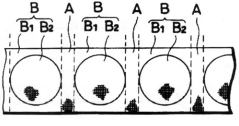
A variety of weaves have been used including a plain, twill or satin weave. Polyester or polyamide yarn can be used in the construction of the bag. The air bag is created using a combination of connected and unconnected double woven constructions. The author explains the process in the following excerpt accompanied by Figure 2.11 (Kitamura, et al., 1998).
“…first, the non-tubular weave structure A is formed by repeating a non-tubular
weave until the predetermined length is obtained and then the tubular weave structure B,
having the connected portion B1 and the non-connected portion B2 is manufactured by
Figure 2.11 Seamless Woven Air Bag (Kitamura, et al., 1998)
The length of the weft yarn across the width of the connected portion, B1 is
decreased and then increased in the non-connected section of B2. The increase in weft
length during the weaving of B2 imparts a tubular or circular shape to the area. After
weaving the fabric is coated with a polymer on both sides. A hole is made in each of the non-connected areas (Kitamura, et al., 1998)
2.1.8 UTILIZING ELASTIC AND NON-ELASTIC YARNS TO CREATE GATHERS AND SHAPED GARMENTS
A study which involved the utilization of elastic and non-elastic yarns to create gathers and shape within a woven fabric was conducted in 1972 by A.P. Singh Sawhney at the Textiles Center, Texas Tech University. Singh Sawhney attempts to introduce a method of weaving he refers to as integral weaving in which an entire garment is woven on the loom. He utilizes a tubular woven construction and yarns with differential shrinkage to create “semi-ready-to-wear” garments (Singh Sawhney, 1972)
Shape and gathers are created in different areas or “Zones” of the fabric by
Figure 2.12 Gathers Created by Utilizing Non-Elastic and Elastic Yarns (Singh Sawhney, 1972)
The shape and the gathers are created from non-elastic and elastic yarns. The warp is a 70 denier yarn which consists of 47% cotton, 47% wool with a 6% elastomeric fiber core. In the weft two different yarns are utilized. In Zone A, a 37 (tex) cotton/wool yarn with a 150 denier elastomeric core is utilized in the weft. The yarn causes
considerable circumferential shrinkage when the fabric is in a relaxed state. In Zone B a regular 12/2 (Ne) cotton yarn which does not cause any appreciable shrinkage in the relaxed state is utilized. After heat-setting the fabric gathers are formed in Zone B, the rigid zone due to the high differential shrinkage from the elastic yarn used in Zone A (Singh Sawhney, 1972).
The varying fabric cover due to differential shrinkage in the different Zones is admittedly a potential problem. A very coarse, soft-spun cotton filling is intentionally used in Zone B in an attempt to produce an acceptable fabric cover. Singh Sawhney suggest that to produce an even more appropriate fabric cover in Zone B which would be compatible to the fabric cover in Zone A, a weave with more intersections could be used in Zone B.
two yarns are utilized, specifically a multiple yarn consisting of a 70 denier elasticomeric core, covered with a cotton/wool in equal blends and a cotton/wool blended yarn. In Zone C a cotton/wool yarn is utilized. Singh Sawhney varies the pick density in an effort to produce a comparable fabric cover. Zone A and Zone C use the same pick density, however, in Zone A the pick density is decreased to half that of Zone B and Zone C (Singh Sawhney, 1972).
Figure 2.13 Gathers Created by Utilizing Non-Elastin and Elastic Yarns (Singh Sawhney, 1972)
Figure 2.14 Sketch of Shaped Dress, Unfinished Dress, Dress After Six Hand Washings(Singh Sawhney, 1972)
Sawhney’s experiment yields some interesting shapes using simple accessible technology, however, there are a number of draw-backs. Elastomeric weft yarns are challenging to weave. Tension of the yarns needs to be controlled throughout the weaving process. A long-drop box chain is necessary when weaving long pick repeat patterns such as with the shaped dress. In addition, consistent fabric tightness is also an important consideration. Sawhney suggests strategically combining different qualities of filling yarns such as fiber type, stretch, bulk, twist, ply and size to achieve compatible fabric cover. He also suggests cramming picks and using tighter weaves with a greater number of filling intersections in more open areas. He states that the garments produced in his experiment have no significant fabric-cover problems. However, if the fabrics were to be dyed significant problems might exist.
2.1.9 UTILIZING AN ADJUSTABLE REED TO PRODUCE A SEAMLESS SHAPED TEXTILE
would be accomplished by contracting the reed where narrower fabric widths were desired or expanding the reed in areas that wider widths were desired. Unfortunately, an adjustable reed has a number of inherent problems (Faber, 2002).
The term “unit” is used by professionals to refer to the thickness of the flat metal wire which comprises part of a dent, and the space between two reed dents. Reeds are designed to have a specific % of the total unit allotted to air space and a specific % of the total unit allotted to wire space. At the initial stages of design, each reed is
engineered so that a fabric with specific aesthetic characteristics and physical properties can be produced. During contraction or expansion of an adjustable reed the unit is changed. Changing the unit has adverse effects on both the aesthetic and physical properties of the resulting cloth. For this reason the design and implementation of an adjustable reed has not yet been pursued (Faber, 2002).
Even if an adjustable reed was produced, some challenges might be encountered if the reed were to be utilized to create shape during the formation of a fabric.
Expanding the reed to widen the width of the fabric would decrease the warp density. Decreasing the warp density would cause increased shrinkage during fabric finishing. The shape produced by expanding the adjustable reed might be negated by the increased shrinkage from the decreased warp density.
2.1.10 UTILIZING A FAN REED TO FORM A SHAPED TUBE
Figure 2.15 Diagram of a Single Fan-Shaped Reed (Faber, 2002)
Figure 2.16 Multiple Fan-Shaped Reed (Seidl and Kellenberger, 1993)
The fan-shaped reed is composed of inclined reed dents (“Fan-Shaped Reed…”).
After the insertion of a specified number of picks, a lever moves the fan-shaped reed up or down. The vertical movement of the reed displaces the warp yarns within each dent. The threads are pushed sideways producing a wavy arrangement as well as varying the number of warp yarns per inch. Figure 2.17 shows the warp displacement that can be achieved using a fan-shaped reed (Seidl and Kellenberger, 1993).
Fan reeds can also be used to produce tubular fabrics with inherent shape. A single fan reed can be installed on a shuttle loom. The single fan reed can be lowered and raised with a lever to produce small adjustments in the warp width. A variety of seamless tubular shapes have been produced using a shuttle loom that has been equipped with a fan-shaped reed, see Figure 2.18.
Figure 2.18 Examples of Tubular Shapes Produced on a Shuttle Loom Equipped With a Fan-Shaped Reed (Faber, 2002)
Unfortunately, fan shaped reeds can only be used on looms in which the reed moves horizontally during the beat-up process. High speed looms such as air and water jet and rapier looms all have reeds that pivot during the up process. During the beat-up process the pivoting motion causes the warp ends to move beat-up and down within the dents. If a fan-shaped reed were to be used the up and down motion within an incline dent would causes the warp ends to abrade and break. In addition, the movement of the warp ends within an inclined dent would result in unintentional fabric width adjustments. For these reasons fan shaped reeds can only be used on a loom in which the reed moves horizontal during the beat-up process (Faber, 2002).
Another disadvantage to utilizing a fan reed to produce inherent shape in a woven fabric is that only a relatively small amount of shape can be achieved. The shape is achieved by moving the fan reed up and down, thereby displacing each warp end within the inclined dent. Only a relatively small amount of shape can be achieved because there is a limited incline in which reed dents can be placed. If reed dents are placed at too steep of an incline, weaving will become difficult. Therefore, if a greater degree of angle is needed the reed would have to be heightened. This would result in a heavier reed, making adjustments of the reed harder and resulting in lower loom speeds.
In addition, a fan shaped reed would displace the ends causing varying warp density within a fabric. Areas with less warp ends would shrink more, whereas areas with more warp ends would lead to less shrinkage. The shape produced by displacing the ends in the fan reed might be negated by the increased or decreased shrinkage caused from varying warp density.
2.1.11 HERMENEUTIC APPROACH TO A SEAMLESS TUNIC
This study was prompted by the author’s fascination of a passage in St John’s Bible. The passage states: “the coat was without seam, woven from top throughout.” The author carefully analyzed the quote in an effort to reproduce the coat as it might have been done many centuries previously. From the statement, “woven from top throughout” the author surmises that the coat was woven on a vertical loom, which was commonly used by early civilizations (Primentas, 1997).
Figure 2.19 Reproduction of a Vertical Loom (Primentas, 1997)
The ends of each warp yarn are secured to pins that are mounted to a block at the foot of the inverted “U” shaped frame. The blocks are grouped accordingly to create the appropriate shed for each pick. One shuttle is passed through designated warp yarns to form the shoulders and the neck opening, see Figure 2.20.
Figure 2.20 Shoulder and Neck Opening (Primentas, 1997)
2.2 OTHER FABRIC FORMING PROCESSES IN WHICH A TEXTILE PRODUCT WITH INHERENT SHAPE CAN BE PRODUCED
2.2.1 SHAPED KNITTING
Recently, the knit industry has undergone some major advances in the
development of seamless whole garment knitting. One of the main factors for exploring and pursuing the ability to produce seamless whole garments was the “labor trap” (Millington, 2000). For a number of years the garment industry has found it difficult to compete on product price with countries that have a plethora of low wage labor available. In addition, the more labor that is required to complete the garment the more vulnerable the garment producer becomes. Interestingly, the break through of whole garment
knitting has been achieved without a single new advancement in the fundamental knitting process adopted by William Lee when he invented the hand stocking frame in 1589. The basic principles of knitting remain the same (Millington, 2000).
Today, there are knitting machines that can either knit shaped panels or seamless whole garments. Knitted shaped panels can be sewn together, thereby eliminating the cutting process. The cutting and sewing process is entirely eliminated by utilizing
knitting machines that produce seamless whole garments. Several machine makers of flat knitting machines are now able to produce whole seamless garments. This is
accomplished by utilizing multi-needle/transfer knitting beds (Millington, 2000). The machine starts by knitting three separate tubes, two sleeves and a bodice. The three pieces are then joined under the shoulder, creating one large tube. The number of active needles is then gradually reduced, so the tube diameter decreases up to the neckline. The collar is then knitted and the garment is finished (Stoll, 1998). There are a number of advantages to full body knitting besides the elimination of the cutting and sewing process. Other advantages include the elimination of uncomfortable seams at the shoulders and underarms and the reduction of fabric waste generated during the cutting process (“Shima Seiki’s…”and Stoll, 1998).
to fashion apparel, there are many potential applications for seamless shaped multi-dimensional fabrics. Seamless shaped knitted fabrics could be used in products designed for the industrial, aerospace, automotive, medical and protective clothing industries (“Flat-Knitting…”). Unfortunately, there are some disadvantages in the manufacture of shaped knits.
The installation of machines capable of knitting full body garments has proceeded with some caution (“Flat-Knitting…”). Countries that have a large population willing to work for low wages can produce huge quantities at very low prices. The capital cost of the knitting time alone on a full body garment machine can still exceed the price that a cut and sewn knitted garment could be purchased for in China (Stoll, 1998).
There are design limitations to the full body knitting machines. Designs can not be applied to both the front and the back panels during knitting. There are also
limitations concerning the type of yarns that can be used. In addition, although fabric waste is eliminated in full body knitting by eliminating the cutting process, waste can be generated through faults. If there is a fault in one of the sleeves, then the other part of the garment has to be thrown away, including the other sleeve and the front and back panels (Stoll, 1998).
In some cases knit constructions do not have the appropriate physical properties and are therefore not suited for some end uses. For example, in medical applications, specifically for implantable arterial prostheses, the performance characteristics vary according to the demands of the location in which they are used. Knitted prostheses are used because they are easy to suture and possess acceptable thrombogenicity, which is the ability to cause blood to clot. These particular characteristics make them
low porosity, therefore they are preferred to knitted grafts in high-pressure flow areas (Savage, et al., 1984).
2.2.2 BRAIDING
Braiding is one of the simplest and oldest forms of fabric production. A braided structure is formed by the diagonal interlacing of yarns. Braiding can be classified as either two-dimensional or three-dimensional. A two-dimensional braid can be either circular or flat. Three-dimensional braiding is relatively new and is mainly used for the production of composites (Adanur, 1995).
2.2.2.1 TWO-DIMENSIONAL BRAIDING
Crossing a number of yarns diagonally so that each yarn passes alternately over and under one or more yarns forms a two-dimensional circular or flat braid. Circular braided structures can be made in many shapes. Circular braids have a hollow center. The tube can be braided about a central core of yarns, producing a solid braid composed of a core and a sleeve. The core can be any shape. The braided structure conforms to the core making it possible to develop braided structures of many different types of complex shapes (Adanur, 1995).
2.2.2.2 THREE DIMENSIONAL BRAIDING
Three-dimensional braiding is relatively new compared to two-dimensional braiding. The first three-dimensional braiding machine was developed in the 1960’s. The process is mostly utilized to produce structural textile composites. As of 1995 there were no commercially available three-dimensional braiding machines. The main reason for this is that every different three-dimensional braided structure requires a different machine with specific characteristics and dimensions. Therefore, companies and academic institutions custom build three-dimensional braiding machines according to their specific needs (Adanur, 1995).
An orthogonal interlacing of multi-yarn systems forms three-dimensional braided structures. In the three-dimensional braided process yarns can be interlaced to form a multilayer 3-D structure (Adanur, 1995). The three-dimensional process can produce a variety of complex shapes. However, limited control, speed, dimensions and precision are associated with the majority of machines. Although there have been recent efforts to minimize these disadvantages, improved machines are not currently commercially
available (Mungalov and Bogdanovich, 2002). In addition, the three-dimensional braided structure is not suited for a variety of end-uses.
2.3 CONCLUSION
Shape within a fabric could be produced by utilizing specific variables, such as different pick densities, various weave constructions and yarns with different degrees of shrinkage. Most textile professionals know that utilizing these variables in a fabric construction will affect the shrinkage of the fabric during finishing. However, the potential for producing a shaped fabric by utilizing these variables has not been fully investigated, researched or well documented.
Typically these variables are carefully chosen at the beginning of the design process to produce minimal and uniform shrinkage. However, they could also be
manipulated to create shape by producing differential shrinkage within the fabric when it was scoured and exposed to heat during the finishing process. Modern textile equipment has made the manipulation of these variables possible. The ability to be able to quickly and easily change and manipulate these variables before the weaving process has made it potentially possible to design shaped fabrics at high speeds and low production costs.
The amount of fabric shrinkage that occurs during finishing is not only attributed to the shrinkage behavior of fibers and yarns but also to the structural features of the fabric. It is important to note that the features that cause shrinkage are interrelated and interdependent. Collins demonstrated that the ends density and the picks density can affect the shrinkage of the fabric. These features as well as yarn size can account for shrinkage’s as large as 10% or more in cotton fabrics (Collins, 1951). However, Collin’s findings were never utilized to create shape. With modern weaving equipment the pick density can be quickly changed at specified areas, enabling fabrics to be woven with the same or different yarn densities. Varying degrees of tightness within the fabric can be obtained by using different filling yarn densities in a woven construction. When fewer filling threads are inserted into the fabric, the fabric is looser. When exposed to heat during the finishing process, the looser areas have more room to come in than the areas comprised of more filling yarns. This results in a higher percentage of shrinkage in the looser areas than in the areas of the fabric that consist of more filling yarns.
Another structural feature of a fabric other than yarn density that can affect fabric shrinkage is the weave design. Different weave designs could potentially be utilized to produce differential shrinkage within a fabric construction and ultimately shape. A woven fabric is formed by interlacing two yarns, the warp and weft, which lie at right angles to one another. The weave pattern is determined by the way in which the warp and filling yarns pass over and under one another or how they interlace. The differential shrinkage between weaves has to do with the number of intersections and the float length per weave repeat.
A plain weave has the maximum amount of interlacings of the weft and warp yarns. Early research on wool fabrics demonstrated that weaves with a high number of intersections such as plain weaves shrank less than weaves with fewer intersections (Johnson, 1938). This basic rule is true regardless of the fiber used in the construction of the cloth. Because twill, satin and basket weaves have fewer interlacings, they are looser weaves than a plain weave. The looser the weave or the fewer the interlacings within a weave repeat, the more room there is for the fabric to come in or shrink when it is exposed to heat during finishing. Therefore, a twill, satin or basket weave would shrink more than a plain weave constructed of the same thread density and yarns.
There are numerous variables that affect fabric shrinkage- including filling yarn density, weave design and fiber type, which affect fabric tightness and ultimately shrinkage. Typically, textile fabrics are designed with reasonable tightness to have minimal uniform shrinkage. However, to produce shape, a high shrink yarn could be used in combination with a lower shrink yarn.
2.4 WORKS CITED
Adanur, Sabit. “Braiding and Narrow Fabrics.” Wellington Sears Handbook of Industrial Textiles. Lancaster PA: Technomic Publishing Company, Inc., 1995: 133-138.
--- “Textile Structural Composites.” Wellington Sears Handbook of Industrial Textiles. Lancaster PA: Technomic Publishing Company, Inc., 1995: 231-268.
Callow, Allan M.D. “History of Vascular Graft Development.” Vascular Graft Update-Safety and Performance. Ed. Kambic, H.E., and Kantrowitz, A. and
Sung, P., Philadelphia PA: ASTM, 1986: 16-15.
Clarke, Steven. “Net Shape Woven Fabrics-2D and 3D.” Journal of Industrial Textiles. 30 (2000): 15-25.
Collins, G.E. “Fundamental Principles that Govern the Shrinkage of Cotton Goods by Washing.” The Textile Institute. December 1951: 46-61.
Faber, Fred. Personal interview. Steelheddle, Incorporated., Greenville, SC. July, 2002.
“Fan-Shaped Reeds: Scope for Come-Back.” The Indian Textile Journal. August 1996: 118-121.
“Flat-Knitting Machinery for Technical Textiles.” Technical Textiles International. November 1999: 20-24
Guyton, Arthur M.D., Function of the Human Body. 4th ed. Philadelphia, PA: W.B. Saunders Company, 1974: 93-106.
Hoffman, Harmon. “Fabrication and Testing of Polyester Arterial Grafts.” ed. Kambic, and Kantrowitz and Sung. Vascular Graft Update: Safety and
Performance. Philadelphia, PA: ASTM Special Technical Publication 898, 1984: 71-81.
Johnson, A., “The Influence of Weave Structures on the shrinkage of Woolen Fabrics in Milling.” The Journal of the Textile Institute. February, 1938. T7-T17.
Kitamura, Asahi, Kogyo, Kabushiki and Kaisha. “Impact Absorbing Air Bag and Method for Manufacturing Same.” United States Patent # 5,707,711. January, 13: 1998.
LaPointe, D.J.E., L.T. Wright, and L.J. Vincent. “Tapered, Tubular Polyester Fabric.” NASA-Case-MSC-21082-1, 1987.
Millington, John. “Complete Garment Manufacture.” Textile Asia. July, 2000: 32-37.
Moreland, Janet. “An Overview of Textiles in Vascular Grafts.” Clemson Conference on Medical Textiles, 1997: 1-11.
Mungalov, Dmitri. And Bogdanovich, Alex. “Automated 3-D Braiding Machine and Method.” United States Patent #6,439,096. August 27, 2002.
Nunez, Jose. And Peter J. Schmitt. Meadox Meidcals. Inc., Oakland NJ. “Shaped Woven Tubular Soft-Tissue Prostheses and Methods of Manufacturing.” United States Patent # 5,904,714. September 1, 1998.
Primentas, N. and Primentas, A. “The Seamless Tunic A Technological and
Hermeneutical Approach.” The 78th World Conference of The Textile Institute. 1997: 415-423.
Savage, Lester and James Smith and Christopher Davis and E.A. Rittenhouse and
Dale Hall and Peter Mansfield. “Dacron Arterial Grafts: Comparative Structures and Basis for successful Use of Current Prostheses. “ ed. Kambic, and
Kantrowitz and Sung. Vascular Graft Update: Safety and Performance. Philadelphia, PA.: ASTM Special Technical Publication 898, 1984: 16-24.
Seidl, Roland and Paul Kellenberger. “Patterning of the Weave by Fan Shpaed Reeds-An Old but Rediscovered Technique.” International Textile Bulletin. February, 1993: 61-66.
“Shima Seiki’s Wholegarment Developments are Ushering in a New Era for Knitwear.” Japanese Textile Machinery. February, 2002: 24-29.
Singh Sawgney, A.P. “Apparel Weaving-A New Concept.” Textile Industries. December, 1972: 50-56.
Stoll, Thomas. “New Knitting Technologies on the Flat Knitting Machine.” International Textile Bulletin. May, 1998: 61-66.
Taws, John. Personal Interview, Fletcher Industries, Southern Pines, NC. September 2003.
Thubrikar, Mano. Personal Interview, Heineman Medical Research, Inc., Charlotte, NC. 2001.
Vasavada, D.A. and P.S. Kanade and M.V. Koranne. “A Novel Method to
Vascutek Ltd. Austin, TX. 2003.