20th International Conference on Structural Mechanics in Reactor Technology (SMiRT 20) Espoo, Finland, August 9-14, 2009 SMiRT 20-Division V, Paper 2006
Structural Integrity Assessment of DHX under CDA Pressure Loading
Sajish.S.D
a, S.Jalaldeen
a, P.Chellapandi
a, and S.C Chetal
aa
Reactor Engineering Group, Indira Gandhi Center for Atomic Research-Kalpakkam,India e-mail:[email protected]
Keywords: CDA, DHX, PFBR
1
ABSTRACT
The reactor assembly (RA) of 500 MWe Prototype Fast Breeder Reactor (PFBR), consists of Main vessel (MV), Inner Vessel (IV), Intermediate Heat Exchanger (IHX), Decay Heat Exchanger (DHX) and Primary Sodium Pump (PSP) along with reactor core. The structural integrity of the entire reactor assembly is to be demonstrated even for most extreme and unlikely events like earthquake and Core Disruptive Accident (CDA). CDA resulting from core meltdown is a very low probability event and hence it is considered as Beyond Design Basis Event (BDBE). Nevertheless as a defence in depth approach, the structural integrity of the RA is demonstrated through complex numerical analysis and experiments on scaled down models. Experiments simulating the CDA conducted on 1/13th scale model of RA demonstrated the integrity of major components like IHX, DHX and PSP against the extreme transient pressure loading resulting from CDA. This paper give the details of the numerical analysis carried out on a 1/13th scale model of the DHX used in the CDA mock-up studies using the pressure distribution obtained form the mock-up study as input and response have been compared with that of prototype which undergoes a pressure loading expected during a CDA event .
2
INTRODUCTION
PFBR is a 500 MWe pool type fast breeder reactor whose construction is in progress at Kalpakkam, India. The entire primary sodium circuit is housed within the MV, which contains about 1100 t of radioactive primary sodium. In the design of various components in RA viz IHX, PSP, DHX etc, primary importance has been given to the safety and all the components of the RA has been designed to take care of extreme and low probability events such as earthquake and CDA. Among these loadings, CDA resulting from core meltdown is a very low probability event and hence it is considered as beyond design basis event. As a defence in depth approach, the structural integrity of the RA under CDA is demonstrated through complex numerical analysis, which involves calculations of fluid transients, structural response and fluid structure interaction effects and also through experiments on scaled down models. Experiments simulating the CDA conducted on 1/13th scale model of RA demonstrated the integrity of major components like IHX, DHX and PSP.
Since the availability of the Decay heat removal system (DHR) has to be ensured even under CDA the integrity of DHX under CDA has to be demonstrated by detailed analysis and validation through experimental. Numerical analysis has been carried out on a 1/13th scale model of the DHX used in the CDA mock-up studies using the pressure distribution obtained form the mock-up study as the loading and response have been compared with that of prototype DHX which undergoes a pressure loading expected during a CDA event predicted from the CDA analysis.
2
3
INPUT PARAMETERS
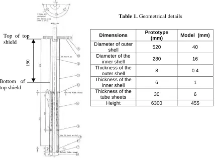
The geometrical details of the model and prototype are explained below. The overall geometry of model is 1/13th of prototype. The overall rigidity and frequency of the model is maintained according to the scaling laws for the accurate simulation of the dynamic behaviour.
The model used for the experimental setup consists of two concentric shells of diameters 40 mm and 16 mm respectively with two rows of tubes of diameter 2 mm and thickness 0.1 mm welded to top and bottom tube sheets as shown in Figure.1. It is connected to the roof slab top using flange bolted connection. The dimensions used for the FEM model of the prototype are taken from the latest drawing of the DHX. One to one correspondence of the scaling ratio could not be maintained between model and prototype because of the design changes in the DHX. The geometrical dimensions are given below.
Table 1. Geometrical details
Figure 1. Schematic of the DHX model
4
LOADING ON DHX
Fast transient analysis of reactor assembly of PFBR for an energy release of 100 MJ has been carried out using in-house code ‘FUSTIN’. The transient loading in the vicinity of DHX has been extracted as shown in Figure.2. It may be seen that the pressure rises to a maximum value around 2.5 MPa in a short period of 22.5 ms in the form of triangular pulse. Similarly experiment has been conducted on a 1/13th scale model of the RA, which includes IHX, DHX, PSP, IV, MV, and roof slab all scale down proportionally. Energy release of 100 MJ has been simulated from the explosion of detonators kept near the core location (Chellapandi et al.2002). This generates a transient pressure pulse, which travels from the core location outward in all directions. Pressure pulse in the vicinity of DHX has been measured which is found to be in the form of a triangular pulse of amplitude 9 MPa as shown in Figure.3. it attains the maximum value within a short period of 1 ms. Small bending was observed in the DHX due to the pressure loading in the experiment. This may be due to the asymmetric pressure distribution momentarily developed around the circumference due to lack of rapid communication of fluid in a short time. Pressure equalizes rapidly due to high sonic velocity in the fluid. Since the outer shell of the DHX is perforated, the high velocity pressure pulse could able to
Dimensions Prototype
(mm) Model (mm) Diameter of outer
shell 520 40
Diameter of the
inner shell 280 16
Thickness of the
outer shell 8 0.4
Thickness of the
inner shell 6 1
Thickness of the
tube sheets 30 6
Height 6300 455
1
9
0
Bottom of top shield
communicate easily with the fluid inside the outer shell and fluid around the DHX, there by bringing down the net effective pressure, ΔP acting on the shells considerably lower than the transient pressure measured near the vicinity of the DHX. There fore the effective pressure, ΔP acting on the DHX shell can be considered as equal to the transient pressure Ptransient measured outside the DHX multiplied by a reduction factor ‘α’. The fore the effective pressure can be written as
ΔP = αPtransient
The reduction factor ‘α’can be considered as same for both model and prototype even though the value will be lesser for prototype as sonic velocity in sodium is higher than that of water. Figure.4 shows the schematic diagram of flow around the shell. From the figure it can be seen that the value of ‘α’ will be << 1 in the case of flow through a perforated shell. The actual value of ‘α’ in this case can be evaluated only by complex fluid structure interaction analysis. In order to get the actual stresses acting on the DHX shell the stresses obtained from the transient analysis for the pressure pulse can be multiplied by the reduction factor ‘α’. Since it is clear from the experiment that the stresses acting on the DHX is predominantly bending in nature, pressure is applied as a cosine distribution as a conservative approximation on one side of the DHX shell to simulate the behaviour during the test as shown Figure.5.
Figure.2 Transient pressure loading on DHX prototype
Δ
t
Figure.3 Transient pressure loading on DHX
model
Δ
t
Δ
t
Figure.4 Differential pressure distribution around DHX Figure.5 Pressure distribution
4
5
FINITE ELEMENT MODELING
The DHX model and prototype is simulated using 4-noded shell elements in CAST3M. The inner shell and outer shell of the DHX is modelled along with tube sheet. Masses of various components have been lumped at the appropriate locations for simulating the dynamic behaviour. Added mass effect of the fluid coupled with concentric shells has been taken care by calculating the equivalent density of the shells which will give the total mass distributed on the shell including added mass of the fluid as shown below. The annular mass is distributed between the inner and outer shell based on the ratio of their surface area (Alok gupta, 2003).
Mass of inner shell = self weight +added mass inside + Di/(D0+Di) x annular added
mass (1)
Mass of outer shell = self weight + mass displaced + D0/(D0+Di) x annular added mass (2)
Annular added mass have been calculated as per the following equation
Madded per unit length = [π(D 2
o – Di 2
)/4] x l x [(Do +Di)/2]/(Do -Di) (3)
Where D0 and Di are inner and outer diameter of respective shells and ρl is the density of the liquid.
1800 sector model has been developed as shown in Figure.6 for the model and prototype respectively to take care of the geometrical and loading symmetry. Fixed boundary conditions are applied at the top as DHX is fixed at the roof slab location. Symmetrical boundary conditions are applied at the plane of symmetry as shown in Figure.7.
Figure.7 Boundary conditions
Fixed boundary condition
Symmetric boundary condition
Figure.6 FE mesh for DHX model and
prototype
Model
6
ANALYSIS
6.1
Natural Frequency Analysis
In order to verify the scaling laws maintained for the model and prototype and to verify the dynamic amplification during the transient loading condition, natural frequency analysis has been carried out for both DHX model and prototype and frequency of bending mode has been compared as given in Table.2.
Table 2. Natural Frequency analysis
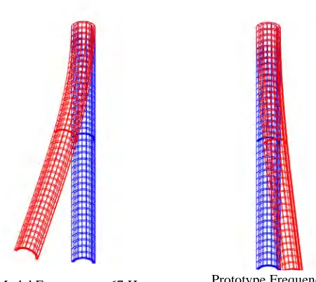
It can be seen from the table that the frequency ratio between model and prototype is (67/5.1) ≈ 13 in line with the scaling laws by which it can be proved that the natural frequency of the 1/nth scale down model will be ‘n’ times that of the prototype. Figure.7 shows the fundamental mode shape of the model and prototype. The period of vibration obtained for the model and prototype can be used to verify the dynamic amplification during the transient pressure loading based on the analytical solution.
6.2
Dynamic Analysis for transient Pressure loading
Response has been calculated for the transient pressure loading for the 1/13th scale model and prototype of the DHX based on Newmark time integration method by appropriately selecting the time step for the integration. Transient pressure load is applied as shown in Figure.9 for model and prototype. Maximum response viz displacement and stress have been extracted at different location of interest. Figure.10 shows the deflection behaviour of the model and prototype in X direction with time. Dynamic response ratio has been calculated using the static analysis result for the same geometry and same load distribution with maximum amplitude of pulse loading applied statically. Maximum dynamic response, static response, dynamic amplification and corresponding time ratio, ‘t /T’ where t is the duration of the pressure pulse and ‘T’ is the time period of the component is reported in Table.3.
SL.No Component Fundamental
frequency (Hz)
1 Prototype 5.1
2 Model 67
Model Frequency = 67 Hz Prototype Frequency = 5.1 Hz
6
Table 3. Comparison of dynamic response (deflection)
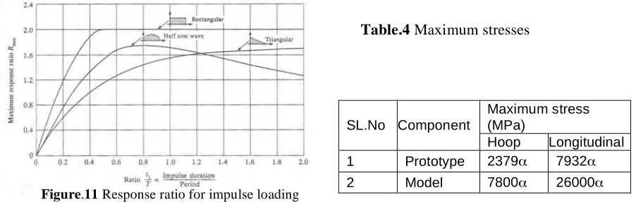
From the results it can be seen that the dynamic amplification factor for the model and prototype corresponding to the respective time ratio is closely matching with value calculated mathematically given in Clough et al.2003 for the triangular pulse as shown Fig.11, giving confidence in the dynamic analysis methodology followed for the response calculation. This also proves that estimating dynamic response under impulse loading can be possible without doing expensive computer simulation in the design stage.
Table.4 Maximum stresses
The stresses at different locations are compared between model and prototype. Figure.12 and 13 depicts the time variation of the hoop stress (h) and longitudinal stress (l)for bottom, middle and top locations of the
SL.No Component t (Sec)
T (Sec)
Time ratio ( t/T)
Static deflection at bottom point
(m)
Dynamic response at bottom point
(m)
Dynamic amplification
Ratio
1 Prototype 45E-3 0.196 0.23 2.49 1.62 0.65
2 Model 2E-3 0.015 0.13 0.77 0.28 0.36
Maximum stress (MPa)
SL.No Component
Hoop Longitudinal 1 Prototype 2379α 7932α
2 Model 7800α 26000α
Figure.10 Displacement response
model and prototype respectively and table.4 gives the details of the maximum hoop and longitudinal stresses developed in the model and prototype. From the table it can be inferred that the stresses developed in the prototype under actual CDA loading condition is less than that of the model under the test condition there by proving that the results obtained from the mockup studies of 1/13th scale model of RA under simulated CDA loading conditions is conservative. It can be noted that this stresses are the most pessimistic estimation without considering the communication effect of fluid inside and outside the shell. In real case the net stresses will be considerably less than this value due to the differential pressure acting on the shell. The realistic stresses acting on the DHX model and prototype therefore can be obtained by multiplying the stresses with the reduction factor ’α’ as shown in the table. As it is evident from the experiment that no damage has occurred for the DHX except small bending due to the unsymmetrical pressure loading the value of the reduction factor α is << 1. Since the stresses in model and prototype are calculated under similar conditions, no need of further correction factor to be applied on temperature.
7
CONCLUSION
Dynamic response analysis has been carried out for the 1/13th scale model as well as prototype of the DHX of PFBR to determine the dynamic response and stresses under transient pressure during a CDA event. Linear response behaviour has been calculated based on a step-by-step integration procedure proposed by Newmark. Transient loading acting on the DHX is idealised to be a triangular pressure pulse whose duration is in the order of milli-seconds derived from detailed analysis. Along the circumference of the shell pressure is assumed to have a cosine distribution. In case of DHX scaled down model, response is calculated for a triangular pulse of amplitude 9 MPa with 2 ms duration while the prototype is analysed for triangular pressure pulse of amplitude 2.5 MPa with 45 ms duration. Analysis results indicates that the maximum displacement ratio i.e. the ratio between maximum dynamic displacement to static displacement, for the model and prototype are matching well with that of the mathematically computed value for the given time ratio. It can be noted that the maximum stress in 1/13th scale model is higher than that of the prototype. So it
Hoop stress
Longitudinal stress
Figure.12 Stress variation for Model
Hoop stress
Longitudinal stress
8
can be concluded that the results of the mock up study conducted on 1/13th scale model of the RA gives a conservative estimate of the actual CDA loading. It is worth mentioning that DHX was not damaged in the experiment and hence the structural integrity of DHX is ensured for the CDA loading for PFBR.
REFERENCES
1. Alok gupta, ,2003 “Seismic Analysis of DHX (Type-A)” IGCAR Internal report
2. P.Chellapandi,2000 “ FUSTIN- A Code for Structural Analysis of Primary Containment Under CDA” IGCAR Internal report
3.