SENSITIVITY OF MODELING TECHNIQUES USED FOR ANALYSIS OF
MODULAR COMPOSITE FLOOR PANELS IN NUCLEAR
SAFETY-RELATED STRUCTURES
Hunter J. Brown1, Damon G. Reigles2, Lisa M. Anderson2, and James L. Ryan3
1 Civil/Structural Engineer, Bechtel Power Corporation, Frederick, MD ([email protected])
2 Senior Civil/Structural Engineer, Bechtel Power Corporation, Frederick, MD 3 Senior Engineering Specialist, Bechtel Power Corporation, Frederick, MD
ABSTRACT
Appropriate use of modular construction is paramount for the success of the nuclear renaissance and the construction of new generation nuclear structures, both to mitigate the project cost and to increase schedule certainty. One method of modular construction involves the use of large shop fabricated composite floor panels, along with associated seated connections. Suitable modeling of modular composite floor systems, including the end restraint, is critical when generating in-structure response spectra (ISRS), which are subsequently used to seismically qualify equipment.
The behavior of a composite floor system depends on a number of factors including the behavior at the seated connection, end-fixity provided by continuity of the reinforced concrete slab, and the degree of composite action. In this paper, a methodology is proposed for validating a modeling approach suitable for dynamic analysis of modular composite floor systems in nuclear safety-related structures.
INTRODUCTION
Nuclear safety related structures, systems, and components must be designed to withstand the effects of a safe shutdown earthquake and remain functional. To determine the seismic demands on these equipment and the supports attaching it to the structure, In-Structure Response Spectra (ISRS) generated from a large-scale finite element analysis are used. This ISRS represents the earthquake motion being filtered through a soil media, then through structural walls, and ultimately to a particular point on a floor slab. The veracity of the ISRS is dependent on the modeling assumptions in any one of the items in this chain.
The purpose of this paper is to introduce a modular composite floor panel, and study how different modeling approaches affect the dynamic behavior of this panel. This purpose is achieved by describing:
The modular composite floor panels, along with their benefits.
The four ANSYS models used in the harmonic analysis.
The sensitivity of the frequency response of the various modeling approaches. Transfer functions obtained from harmonic analysis in ANSYS are used for this end.
DESCRIPTION OF MODULAR PANELS
m) long are shop fabricated. Figure 1 shows such modular composite floor panels in a construction lay-down area and in the final installed condition.
Each modular composite floor panel is comprised of two primary parallel beams, infill beams, composite deck, closure strips/angles and steel headed stud anchors. Heavily coped ends are provided to mitigate headroom issues, as well as to facilitate the use of seated connections with oversize holes. Significant improvement to construction schedule time can be achieved through the use of shop fabricated modular composite floor panels. These panels (built from structural and miscellaneous steel) are typically installed at a rate of less than 10 hours per ton (11 hours per metric ton), which is considerably lower than the average rate for conventional “stick-built” structural steel (i.e., 15 hrs per ton [16 hours per metric ton]) and miscellaneous steel (i.e., 50 hrs per ton [55 hours per metric ton]).
Improved efficiency in construction schedule time can be attributed to two major sources. First, increased installation efficiency is achieved by shop fabricating modular composite floor panels, which is due in large part to a significant reduction in the number of bolts required during installation. The reduction is achieved by specifying shop welds for infill steel beam connections to the primary beams, and by providing seated connections at the ends of the primary beams that require only two-bolts per connection, regardless of load (see Figure 2). This results in a total of eight bolts per modular composite panel, which is a considerable reduction in the required number of bolts as compared with conventional “stick-built-framing” in nuclear safety-related structures, where up to 50 bolts may be used for an equivalent floor area with thick reinforced concrete slabs and high vertical seismic loads. Second, increased installation efficiency is achieved by a 90 percent reduction in the quantity of structural and miscellaneous steel pieces to be installed. Almost all of the time consuming miscellaneous steel work is performed in a fabrication shop, rather than at elevated heights in the field.
(a) (b)
Figure 1. Modular Composite Floor Panels: (a) In Construction Lay-Down Area and (b) Final Installation
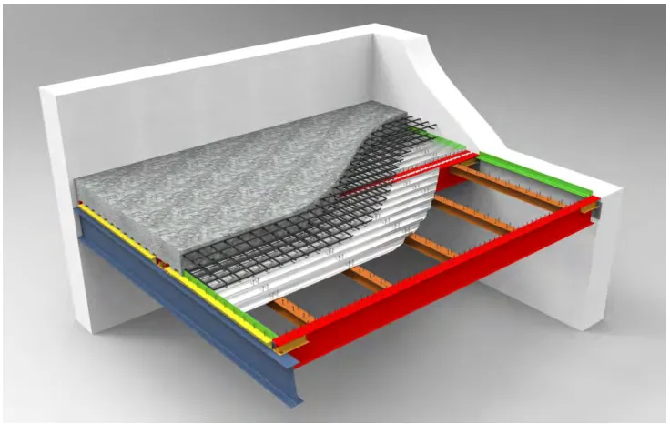
For the specific use of modular composite panels in new generation nuclear structures, a minor modification is made to the panels shown in Figure 1, whereby the deck span is parallel to the primary beams, as shown in Figure 2. In addition to providing increased headroom, this configuration allows for a higher degree of composite action. Specifically, since deck flutes do not cover the flange, more (and larger diameter) studs may be welded to the beam, and the stud reduction factor that is required with the use of steel deck can be avoided. In this configuration, infill beams now serve as the support for the composite deck, while also providing support points for commodities like piping, HVAC and electrical raceway.
avoided through the use of girders that cantilever over partial height interior columns. These cantilevers induce negative moment in the main span, as well as reduce the infill span length.
Figure 2. Isometric View of Example Modular Composite Floor Panels in Nuclear Structures
Non-composite girders are often not viable for nuclear safety-related structures, since columns are typically full height, precluding the aforementioned cantilever framing. In addition, girder stiffness and strength significantly greater than a non-composite girder is frequently required to limit commodity support differential displacements, as well as to withstand the high seismic loads associated with thick concrete slabs and heavy equipment. To facilitate composite behavior, yet allow for the seated connections, a composite stub-girder design previously used in commercial construction is used, as illustrated in Figure 2 (see also Bjorhovde 2005; AISC 1980).
Design of nuclear safety-related structures requires satisfying a number of additional constraints and functional requirements that typically result in slab thicknesses much greater than is commonplace in commercial and industrial building structures. Such increased thicknesses reflect high in-plane diaphragm forces, radiation shielding requirements and/or equipment anchorage requirements. As such, the reinforced concrete slab provides significant end restraint at the ends of composite beams. The coped structural steel and seated connection at the ends of the composite beams (see Figure2) is provided primarily to simplify placement of the modular composite panel with a crane, and it also facilitates a greater degree of certainty with respect to modeling of the end restraint.
EXPECTED BEHAVIOR AND MODELING IMPLICATIONS
Also, any composite floor system has a shear transfer mechanism between the two or more materials. For this system, steel headed stud anchors are used. These stud anchors are inherently flexible, and exhibit yielding under high shear demands. As a result, the stud anchors are known to influence floor system stiffness. However, the numerical models in this study neglect this effect for two reasons: in nuclear structures, the state of stress tends to preclude any stud anchor yielding (i.e., designed to be elastic); also, the influence of stud anchor flexibility on stiffness will equally affect all the models. The intent of these studies is to evaluate differences in modeling techniques, not to match test data. Therefore, the steel beams are assumed to maintain compatibility with the reinforced concrete slabs.
Another behavior to consider is the degree of cracking in the reinforced concrete slab. This cracking represents a reduction in stiffness as loading increases. However, the models used in the following studies do not consider cracking of the concrete.
The steel beams in the modular composite floor panels presented herein are heavily coped. The cope depth is dependent on the connection demands. However, to simplify the number of parameters that are varied in the study, the depth of the steel beam from centerline of the flange to top of cope is held constant at 8 in. (203.2 mm) while the depth of cope is varied for different sized beams (see Figure 4). This approach is considered reasonable since one of the secondary intentions of the steel beam cope is to limit end restraint of the steel beams, such that the floor response at the ends is dominated by response of the concrete slab.
At locations where the composite floor connects to concrete walls the heavily coped steel beam connections sit on beams seats, which are connected to the reinforced concrete wall through an embed plate. The behavior of the floor system in this area tends to be sensitive to the connection details. There are several sources of flexibility in the system: the bolts connecting the coped beam to the beam seat, the beam seat, and the embed plate anchors connecting the beam seat to the wall. For the purposes of this study, the model neglects this complex connection behavior, and only considers the beam seat as a vertical support. This approach is considered reasonable since this support condition could be achieved by using a “clamp plate” steel connection, which allows the beam to slide longitudinally and engages the reinforced concrete diaphragm for all lateral loads.
DESCRIPTION OF MODELS
Four types of finite element models are created in the software package ANSYS (2010) to study the convergence of a shell/beam model, where the concrete slab is modeled with shell elements and the steel beams are modeled with beam elements, that would be used in a large scale finite element model of a nuclear structure. Three span lengths are considered with the following steel member sizes: W24x68 for the 30 ft (9.1 m) span, W30x99 for the 40 ft (12.2 m) span, and W36x135 for the 50 ft (15.2 m) span. Additionally, four thicknesses are considered: 8 in. (203.2 mm), 15 in. (381 mm), 21 in. (533.4 mm), and 30 in. (762 mm).
Description of the Single-Panel SOLID/SHELL Finite Element Model
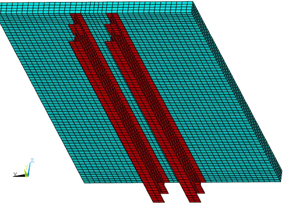
The Single-Panel SOLID/SHELL finite element model uses ANSYS SOLID185 elements, which are defined by eight nodes with three translational degrees of freedom at each node, to model the reinforced concrete slab and ANSYS SHELL181 elements, which are defined by four nodes with six degrees-of-freedom at each node, to model the steel beam. The element size is established at one-fourth of the slab thickness (e.g., a 2 in. [51 mm] element size is used for the 8 in. [203 mm] thick slab). An isometric view of Single-Panel SOLID/SHELL finite element model developed in ANSYS is shown in Figure 3.
matching the nodes of the steel beam flange shell elements to the reinforced concrete slab solid elements (i.e., compatibility is forced between the two materials).
To limit the number of cases studied, standard geometry parameters are established: the steel beam cope depth leaves the top 8 inches (203 mm) of the beam intact, the tributary slab width is 11.0 ft (3.4 m), and the boundary conditions for the steel beams are modeled as a roller supports. There are a total of 16 cases that were studied for the Single-Panel SOLID/SHELL model, i.e., 4 slabs thicknesses and 4 span lengths.
X Y
Z
Figure 3. Isometric View of ANSYS Single-Panel SOLID/SHELL Model Looking from Below
X Y
Z
X Y
Z
Tributary Width
Plane of Symmetry Plane of Symmetry
Flange Width
Depth of Web
Depth of Cope
8 in. (203 mm)
6 in. (152 mm) Depth of Cope Slab Thickness
Depth of Stiffener
Slab Thickness
(a)
(b)
Figure 4. ANSYS Single-Panel SOLID/SHELL Model: (a) Cross Section View and (b) Side View
Description of the 5-Panel SOLID/SHELL Finite Element Frame Model
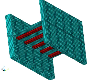
A 5-Panel SOLID/SHELL finite element model was created to study the effects of wall-slab interaction. An isometric view of the 5 panel detailed finite element frame model is shown in Figure 5. This 5-Panel model is identical to the Single-Panel SOLID/SHELL model, except 5 ft. (1.52 m) thick and 3 ft. (0.91 m) thick walls are added at either end. Below is a summary of the model details:
A total width of 55 ft. (16.76 m) is used
20 ft. (6.10 m) high walls are included at each end of the frame (wall thicknesses are 5 ft. [1.52 m], and 3 ft. [0.91 m], respectively)
X Y
Z
Figure 5. Isometric View of ANSYS 5-Panel SOLID/SHELL Element Model Looking from Below
Description of the Single-Panel SHELL/BEAM Finite Element Model
A Single-Panel SHELL/BEAM model is also used to represent the modular composite floor system. This simplified modeling approach is intended to be representative of models typically used to analyze large buildings, where minimizing modeling complexity is important to work within the limitations of present day computing hardware. The properties of the beam elements used to model the steel composite beams are modeled with equivalent composite properties as shown in Equation 1 below:
2
2composite steel
steel steel composite
slab slab
equiv
A
CG
CG
I
A
CG
CG
I
(1)Where Aslab is the gross slab area, CGslab is the center of gravity of the slab, CGcomposite is the center of gravity of the composite cross section, Isteel is the strong axis moment of inertia of the steel shape, Asteel is the cross sectional area of the steel shape, and CGsteel is the center of gravity of the steel section.
ANSYS BEAM44 and ANSYS SHELL181 elements are used in the analyses.
There are a total of 96 cases that were studied for the Single-Panel SHELL/BEAM finite element model, i.e., four slab thicknesses times four spans times six mesh divisions (4, 6, 8, 10, 20, and 40 divisions).
Description of 5-Panel SHELL/BEAM Element Model
The last model considered in the study is a 5 Panel SHELL/BEAM element model. It is modeled with similar techniques as used for the Single Panel SHELL/BEAM panel, except walls are included as supports just like the 5-Panel SOLID/SHELL model. The major exception is that the walls are represented using the centerline dimension of the walls. This modeling approach causes the effective span (from centerline to centerline), to increase by half the wall thickness on either side, or 4 ft. (1.22 m) total for the 5 ft. (1.52 m) and 3 ft. (0.91 m) wall thicknesses used in this study.
SENSITIVITY OF MODELS TO DYNAMIC ANALYSIS
Transfer functions are used to evaluate and compare the frequency response of the four models considered in this study. The transfer functions represent the ratio of the output acceleration frequency response function to the input acceleration frequency response function. This analysis is performed using the ANSYS (2010) software package. A harmonic analysis is performed applying acceleration as a body force, the magnitude and phase angle of the displacement are extracted, which is then converted to a pseudo-acceleration. The Single-Panel and 5-Panel SOLID/SHELL models are considered as a benchmark for comparing the less complex SHELL/BEAM models. Transfer functions from the various models are provided in Figures 6 and 7.
Although various mesh divisions are presented in Figures 6 and 7 for the SHELL/BEAM model, it is recognized that for large finite element models needed to represent typical nuclear structures the practical limit on number of divisions is 10 divisions or less for floor panels. One reason for this is present day expectations that models used for design basis analysis of non-seismic loading are also used as models for soil structure interaction (SSI) analysis. Using very refined mesh sizes for floor panels leads to small element sizes on exterior walls, where interaction nodes are present in the SSI models. The number of interaction nodes in the SSI model has the largest influence on the total run time. Mesh size concerns are amplified with the next generation of nuclear power plants as they are expected to be primarily embedded below ground. This increases the computational demands on the SSI analysis, and increases run times. As a result, it is crucial that mesh sizes be optimized to capture what is required, while omitting unnecessary finite element mesh refinement.
Before presenting the results of the transfer function analysis, a few notes should be made about the convergence of typical models:
In general, as a mesh is refined, the model tends to show greater flexibility (lower frequencies in this case).
As the SHELL/BEAM model mesh is refined, the effective offset of the beam from the end
of the wall is reduced. That is, the first beam element without a moment release moves closer to the end support because the length of the element with a moment release is being reduced.
The SOLID/SHELL models are capable of capturing the shear deformation through the cross section of the composite section, while the SHELL/BEAM models are formulated assuming shear deformation does not occur through the composite cross section (plane sections remain plane).
The SHELL/BEAM models will tend to under-predict frequency (more flexible) because
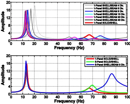
Results from the transfer function analysis are presented in Figures 6 and 7. Although four spans were studied, only the 30 ft. (9.14 m) and 40 ft. (12.19 m) spans are presented below since these are the most representative spans for a nuclear structure using composite beams. Also, the frame SHELL/BEAM results are plotted only for the 8 division mesh size.
A few observations can be made from the Single-Panel plots:
4 and 6 divisions are inadequate to capture the first mode frequency within an acceptable
degree of accuracy.
8, 10, 20, and 40 divisions tend to capture the first mode well, with 40 divisions nearly matching the first peak of the SOLID/SHELL models.
(a) Thick. = 8 in. (203.2 mm), Span = 30 ft. (9.14 m) (b) Thick. = 8 in. (203.2 mm), Span = 40 ft. (12.19 m)
(c) Thick. = 15 in. (381 mm), Span = 30 ft. (9.14 m) (d) Thick. = 15 in. (381 mm), Span = 40 ft. (12.19 m)
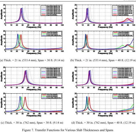
(a) Thick. = 21 in. (533.4 mm), Span = 30 ft. (9.14 m) (b) Thick. = 21 in. (533.4 mm), Span = 40 ft. (12.19 m)
(c) Thick. = 30 in. (762 mm), Span = 30 ft. (9.14 m) (d) Thick. = 30 in. (762 mm), Span = 40 ft. (12.19 m)
Figure 7. Transfer Functions for Various Slab Thicknesses and Spans
The concrete slab drives the response of the floor system. That is, although the beam element approaches the end support (stiffening the system), the more refined shell elements tend to decrease the first peak frequency.
For second mode responses, only the 20 divisions and 40 division models capture the peaks
well. However, these higher modes have much less mass participation and are representative of local responses of the floor.
For the 5-panel plots:
Fixed boundary conditions are a good approximation only for the thinner 8 in. slab. As the
relative stiffness of the slab increases, the walls provide less relative end restraint.
The frame SHELL/BEAM model under-predicts frequencies.
For first-mode frequencies, values differ from the benchmark by between 2-6 Hz for the
cases shown. This is a result of the centerline approximation used to model the walls.
CONCLUSIONS
The purpose of this study is to introduce a modular composite floor panel, and evaluate how different modeling approaches influence the ability to reasonably predict dynamic behavior. A concept for the use of modular composite floor panels in nuclear safety-related structures is presented in this paper. Also, the dynamic sensitivity of four models is studied using harmonic analysis and comparing transfer functions.
Based on the results of the comparison of the Single-Panel models, it can be observed that:
4 and 6 divisions are generally inadequate to capture fundamental frequencies of the floor
system with an acceptable amount of accuracy.
20 divisions is required to capture second-peak responses.
8 divisions represent a reasonable compromise in terms of capturing fundamental
frequencies while keeping the model size practical.
Conclusions from the 5-Panel model comparison study are that for short spans and thick walls a SHELL/BEAM model may significantly under-predict frequency as compared with a SOLID/SHELL model. While the issue associated with modeling centerline dimensions is widely known, it highlights the need when concerned about ISRS to include a ‘stiff’ case to bound the problem, especially when high frequency seismic motion is being designed for. However, for broad-band frequency input, this may give conservative results since there are more peaks in the 50-100Hz region.
In general, using a beam moment release on both ends of the span captures the coped, seated connection used for the modular composite panels presented. Additionally, using an equivalent composite beam cross section modeled at the centerline of the shell is a good substitution for an eccentric steel beam.
FURTHER RESEARCH
There is no full-scale test data available for composite beams with slab thicknesses in excess of 12 inches and other dimensions similar to those that would be used in a nuclear structure. There is a need for full-scale tests to validate results observed from numerical studies, such as presented herein. If data were available, more detailed nonlinear finite element models could be created to capture the true response of this system. These models may be more capable of capturing additional complexities, such as hysteretic damping and the nonlinear stiffness effects that influence overall floor system response. One major limitation of this system is for linear modeling techniques, accelerations greater than 1 g cannot be captured because it represents multiple stiffnesses (i.e., discrete ‘up’ and ‘down’ stiffnesses). If test data were available, it may be possible to use an equivalent stiffness which captures this behavior.
REFERENCES
AISC (1980). “Some Aspects of Stub Girder Design”, Engineering Journal, American Institute of Steel
Construction.
ANSI/AISC 360-05 (2005). Specification for Structural Steel Buildings, American Institute of Steel Construction, Inc. Chicago, IL.
ANSYS (2010). ANSYS Mechanical APDL Element Reference, Release 13.0, ANSYS, Inc., Canonsburg,
PA, November.
Bjorhovde, R. (2005). “Stub Girder Floor Systems,” Handbook of Structural Engineering, 2nd Edition, Chapter 33, Ed. Chen, W.-F. and Lui, E. M., CRC Press, Boca Raton, FL.