An Experimental Study on Effect of Diameter
of Rebar on Exterior Beam Column Joint
Rekha S Patel
1, Nambiyanna B
2, Dr.R.Prabhakara
3Research Scholar, Department of Civil Engineering, M.S.Ramaiah Institute of Technology, Bangalore, Karnataka, India1
Assistant Professor, Department of Civil Engineering, M.S.Ramaiah Institute of Technology, Bangalore, Karnataka, India2
Head of Department, Department of Civil Engineering, M.S.Ramaiah Institute of Technology, Bangalore, Karnataka, India3
ABSTRACT: In reinforced concrete frames the structural elements like beams, columns and slabs play an important role for the overall integrity of structure. Beam column joints transfer the forces & moments effectively to the adjoining members ensuring continuity of structures. The integrity of structure is not affected when static loads acts, but when cyclic loads are encountered, the efficiency of beam column joint is reduced. In the present experimental study an attempt has been made to study the performance of exterior beam column joint by varying the diameter of reinforcing bars, and providing closed spaced stirrups under static load. Various aspects such as ultimate load carrying capacity, deflection, ductility & crack patterns have been studied. In the conclusions it was observed that the bar diameter and spacing of stirrups influence the cracking and ultimate load of beam column joint.
KEYWORDS:Exterior joint, Static load, Crack pattern, Ductility, Diameter of rebar
I. INTRODUCTION
A beam column joint is defined as the portion of the column within the depth of the deepest beam that frames into the column. In a moment resisting frame, three types of joints can be identified i.e. interior joint, exterior joint and Corner joint. Fig.1 shows types of beam column joints in a structure. When four beams frame into the vertical faces of a column, the joint is called as an interior joint. When one beam frames into a vertical face of the column and two other beams frame from perpendicular directions into the joint, then the joint is called as an exterior joint. When a beam each frames into two adjacent vertical faces of a column, then the joint is called as a corner joint.
Fig 1: Types of beam column joints (source: ACI 352R-02)
and weak beam concept‟ so that the plastic hinges are formed in the beam prior to column and the failure is less likely to be catastrophic. The behaviour of joint is influenced by various parameters such as longitudinal reinforcement of beam, stiffness ratio of beam and column, bond conditions, column axial load, grade of concrete, and stirrup ratio. Therefore great attention has to be paid on these parameters. Strength and ductility of beam column joint plays a very important role in the seismic behaviour of framed structures, however our study is restricted to static load only. Though many parameters affect in this present experimental study importance is given to the diameter of bar keeping the reinforcement ratio constant and spacing of stirrups in beam.
II. LITERATURE REVIEW
It has been observed from past, many experimental researches have been carried out on exterior beam column joint to study its exact behaviour under various parameters. Some of the very important parameters are enlisted below:
a) Amount & detailing of reinforcement- It has been found that the additional reinforcement in the joint core increases the overall performance of joint in terms of strength, ductility & stiffness degradation and shear resisting capacity also increases [2]. Cross inclined cross bar pattern shifts the formation of plastic hinges away from the joints and thereby absorbs more energy [4].
b) Grade of concrete-With the use of high grade concrete or high strength concrete, increased compressive and tensile strength and elastic modulus can be achieved thus increasing the overall performance of joint but it exhibits less ductile behaviour. Joints with same grade of concrete in beam and column have more rotation capacity [1]. Cylindrical compressive strength of concrete influences the load carrying capacity.
c) Effect of longitudinal reinforcement- Ductility and strength of depend on the area of tensile and compression reinforcement and distribution of transverse reinforcement [1]. Beam column joint with increased beam reinforcement in addition to diagonal stirrups performed better in terms of load carrying capacity, ductility, stiffness, energy dissipation capacity [5]. Increase in percentage of beam and column reinforcement increases the load carrying capacity [6].
d) Shear reinforcement-With increase in percentage of shear reinforcement the ultimate strength increases at high axial loads [1]. Stress distribution inside the joint was better as the stirrup ratio increased [3]. With increase in spacing of stirrups, the load carrying capacity decreases [5].
III.DETAILS OF EXPERIMENTAL PROGRAMME
A total of six specimens were casted by varying the diameter of tensile reinforcement bars in beam and spacing of stirrups in beam. Standard test procedure has been adopted in the research laboratory at department of civil engineering, M.S.Ramaiah Institute of Technology, Bangalore.
a) Materials- Ordinary Portland Cement 43 grade conforming to IS: 12269 (1987) was used. The fine aggregate used was river sand passing through 4.75 mm IS sieve and having a fineness modulus of 2.35 and specific gravity of 2.53. Coarse aggregate passing 12.5 mm and retained on 4.75 mm having a fineness modulus of 6.25 and specific gravity of 2.627 were used. The 28 day compressive strength of 150x 150 mm cube was found to be 42.85 N/mm2. Steel reinforcement Fe-500 HYSD bars were used for the present investigation.
b) Mix proportion- Mix proportions for M30 grade concrete were obtained based on the IS 10262-2009. The details of mix proportions thus obtained are given in Table 1. The mix proportion used is 1:1.88:3.28 with W/C ratio 0.55.
Cement Fine
aggregate
Coarse
c) Details of test specimen- The cross section of the column was 230mm × 160mm and its length was 1000mm. The beam size was 160mm x 230mm and its length was 600mm, measured from the face of the column. In all the specimens, column reinforcement was kept constant. The columns were reinforced with 4# of 16mm diameter and transverse reinforcement of 8mm diameter bars @ 160mm c/c spacing was provided. The beams were reinforced @ tensile face with 6 # of 8mm, 4 # of 10mm & 3 # of 12mm diameter bars in BCJ1, BCJ2 & BCJ3 respectively and at the compressive face 2 # of 8mm diameter bars were used. In first 3 specimens the spacing of shear reinforcement was kept 150mm C/C and in other specimens BCJ4, BCJ5, BCJ6 it was 100mm C/C. Table 2 shows the details of test specimens and Fig. 2 shows the reinforcement details of beam column joints with stirrup spacing 150 mm c/c in beam.
Specimen Diameter of bar (mm)
No.of bars
Pt (%) Ast (mm2) Spacing of stirrups (mm c/c)
Development Length in Tension
(mm)
Compression (mm) BCJ1 8 6 0.937 301.59 150 363 290 BCJ2 10 4 0.981 314.15 150 453 290 BCJ3 12 3 0.986 339.29 150 544 290 BCJ4 8 6 0.937 301.59 100 363 290 BCJ5 10 4 0.981 314.15 100 453 290 BCJ6 12 3 0.986 339.29 100 544 290
Table 2: Details of Test Specimens
(c)
Fig 2: Reinforcement details for beam column joint-(a) BCJ1 (b) BCJ2 (c) BCJ3
d) Preparation of form work - Wooden moulds of required size were prepare and were used as formwork for casting of beam column joint as shown in fig.3(a). The inside portion and corners of the moulds were properly greased for easy removal of specimen. Cover blocks of thickness 25mm were used at the bottom of the form work above which reinforcement cages were placed as shown in fig.3(b) & fig.3(c) .
(e) (f) (g) Fig 3: a) wooden mould, b) Reinforcement cages, c) Placing of reinforcement e) Placing of concrete,
f) Demoulding, g) Curing
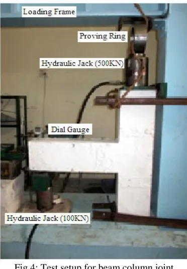
f) Test arrangement and test procedure- After the curing was completed; the beam column joints were white washed before mounting to the loading frame. Fig.4 shows the test setup in laboratory for beam column joint.
Fig 4: Test setup for beam column joint
The exterior beam column joint specimens were tested under a loading frame of 100 tonnes capacity for static loading.
The specimens were mounted and hydraulic jack was placed at the centre using plumb bob.
An axial load of 130 KN (calculated safe load of column) was applied on column by means of 500 KN hydraulic jack.
A point load was applied to the beam end at a distance of 100 mm from end. Load was applied in upward direction.
Dial gauge was used to measure the deflection at every load increment of 2 KN.
Crack width of first crack was measured at intervals using crack width measuring instrument.
Test was continued till the specimen reached its ultimate failure.
IV.EXPERIMENTAL RESULTS
a) Load carrying capacity & Deflection- All the specimens were tested for ultimate failure. The deflection at free end of beam was measured for every 2 KN load increment and cracks were noted and measured using crack microscope. Table 3 shows first crack load, ultimate load and ultimate deflection for all the specimens. For specimen BCJ1, having 8mm diameter bars the Ultimate load carrying capacity was 80KN whereas for specimen BCJ3, having 12mm diameter bars the Ultimate load carrying capacity was 76KN. It was observed that specimens (BCJ1 & BCJ 4) having smaller diameter bars had better load carrying capacity and ultimate deflection compared to other specimens having larger diameter bars due to better stress distribution in smaller diameter bars. It was also observed that by reducing the spacing of stirrups a better load carrying & ultimate deflection can be obtained. For specimen BCJ4, having 8mm diameter bars, the Ultimate load carrying capacity was 82KN whereas for specimen BCJ6, having 12mm diameter bars the Ultimate load carrying capacity was 78KN. Fig. 5 & 6 shows a comparative graph of first crack load and ultimate load for different beam column joint.
Specimen First Crack Load (KN)
Ultimate Load (KN)
Ultimate Deflection (mm) BCJ 1 22 80 23.171 BCJ 2 19 78 24.89 BCJ 3 16 76 25.646 BCJ 4 23 82 22.958 BCJ 5 21 80 25.077 BCJ 6 18 78 26.317 Table 3: Load Deflection values of Exterior beam column joint
Fig 6: Comparative Load-Deflection Graph for all specimens
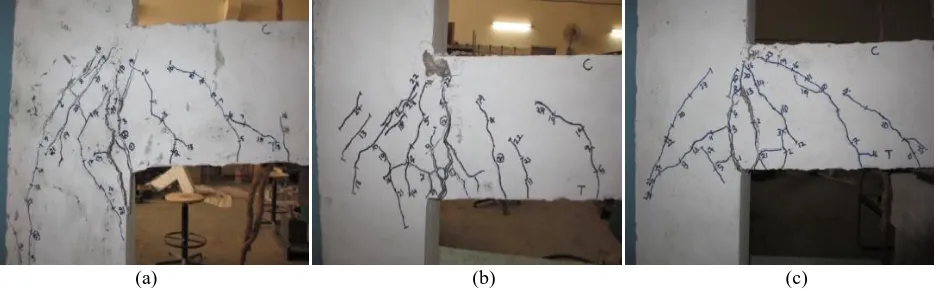
b) Crack width & crack pattern- The crack patterns of all the specimens are shown in Fig.5. (a) shows the crack pattern of 8mm diameter bars i.e. BCJ1, (b) shows the crack pattern of 10mm diameter bars i.e. BCJ2 & (c) shows the crack pattern of 12mm diameter bars i.e. BCJ3. In all the specimens first crack appeared at the beam column joint. It was observed that the first crack widened as the load was eventually increased. Vertical cracks and diagonal cracks were formed. Specimens having smaller diameter bars had multiple and closely spaced cracks thereby arresting the crack propagation. The crack width was increased with increase in diameter of bar. The first crack load for BCJ1 was at 22kN whereas for BCJ2 crack appeared at earlier load i.e. 16KN. The first crack load for BCJ4 was at 23kN whereas for BCJ5 crack appeared at earlier load i.e. 18KN.
c) Ductility- It is defined as the ability to undergo large deformation beyond the initial yield deformation prior to collapse. In the present study ductility factor is defined as the ratio of maximum deflection to yield deflection. It was observed that as the diameter of bars increased the ductility factor decreased. Also with increase in stirrups better ductility factor was noted. Ductility factor values of all the specimens are given in Table 4and Fig.7 shows comparative graph of ductility factor for allspecimens.
Specimen Maximum deflection (mm)
Ductility factor
BCJ 1 23.171 3.80 BCJ 2 24.89 3.41 BCJ 3 25.646 2.97 BCJ 4 22.958 3.87 BCJ 5 25.077 3.66 BCJ 6 26.317 3.14
Table 4: Ductility Factor
Fig 7: Comparative Ductility Graph
V. CONCLUSIONS
From the experimental study on exterior beam column joint under static load, the following conclusions were drawn: 1. The Ultimate load carrying capacity increased with decreasing the diameter of reinforcing bars and thereby the
ultimate deflection also decreased. For BCJ1 the load carrying capacity increased and the deflection reduced by 10% compared to BCJ2 & BCJ3.
2. For beam column joints with closer stirrup spacing, better load carrying capacity and ultimate deflection compared to specimen having larger spacing of stirrups. For BCJ4, the deflection reduced by 14% compared to all the specimens.
3. It was observed that bar distribution affects the crack width. By providing smaller diameter bars the bond between concrete and steel was increased which resulted in less crack width.
ACKNOWLEDGEMENT
We sincerely thank management, CE,Principal and Head of Department of M.S.Ramaiah Institute of Technology, Bangalore-560054, affiliated to VTU, Belgaum for the facility provided to conduct the experimentation and all the technical guidance.
REFERENCES
[1] A.K.Kaliluthin, Dr.S.Kothandaraman, T.S.Suhail Ahamed, “A Review on Behavior of Reinforced Concrete Beam Column Joint”, International Journal of Innovative Research in Science, Engineering and Technology, Vol. 3, Issue 4, pp.11299-11312, April 2014. [2] Kaliluthin.A.K, Kothandaraman.S, “Experimental investigation on behavior of reinforced concrete beam column joint”, International
Journal of Civil and Structural Engineering, Vol. 4, Issue 3, pp.248-261, 2014.
[3] Vladimir Guilherme Haach, Ana Lucia Homce De Cresce El Debs, Mounir Khalil El Debs, “Evaluation of the Influence of the column axial load on the behavior of monotonically loaded R/C exterior beam–column joints through numerical simulations”, Engineering Structures 30 pp. 965–975, 2008.
[4] Suhasini M Kulkarni, Yogesh D Patil, “A Novel Reinforcement Pattern for Exterior Reinforced Concrete Beam Column Joint”, Procedia Engineering 51, pp.184 – 193, 2013.
[5] Bindhu K.R, Sreekumar K.J, “Seismic Resistance of Exterior Beam Column Joint with Diagonal Collar Stirrups”, International Journal of Civil and Structural Engineering, Vol. 2, Issue 1, pp.160-175, 2011.
[6] Ravi Kiran , Giovacchino Genesio,” A case study on pre 1970s constructed concrete exterior beam-column joints”, Elsevier, Case Studies in Structural Engineering, pp.20–25, 2014.
[7] S. Rajagopal, S. Prabhavaty, “Seismic behaviour of exterior beam column joint using mechanical anchorage under reversal loading: An experimental study”, IJST, Transactions of Civil Engineering, Vol. 38, No. C2, pp 345-358, 2014.
[8] S. Sheela, B. Anu Geetha, “Studies on the Performance of RC Beam–Column Joints Strengthened Using Different Composite Materials”, J. Inst. Eng. India Ser. A, 93(1), pp.63–71, 2012.