ABSTRACT
MILLER, ANTHONY D. Repair of Impact-Damaged Prestressed Concrete Bridge Girders Using Carbon Fiber Reinforced Polymer (CFRP) Materials. (Under the direction of Dr. Sami Rizkalla).
Over-height vehicles impacting prestressed concrete (PS) and reinforced concrete
(RC) bridge girders is a frequent problem experienced by the majority of transportation
departments all over the world. The most common practice used to restore a damaged bridge
is to cut out the damaged girder and replace it with a new one. More recently, alternative
methods have been examined to help decrease the costs of replacing damaged girders and
minimizing closure time. The research reported in this thesis considered three scenarios to
examine the effectiveness of using Carbon Fiber Reinforced Polymers (CFRP) to restore
impact-damaged PS girders to their original capacity. The first scenario investigated the
effectiveness of CFRP sheets to repair a 54 ft (16.4 m) long girder with one ruptured
prestressing strand caused by an over-height vehicle impact. The second scenario
investigated the effectiveness of CFRP sheets to repair two 54 ft (16.4 m) long girders with
various numbers of prestressing strands ruptured artificially at midspan. The final scenario
examined the effectiveness of CFRP sheets to repair a shear-critical specimen with four
prestressing strands artificially ruptured near the support.
The design of all CFRP repair systems was conducted using a cracked section
analysis and/or guidelines for shear capacity of prestressed members. The predictions
according to the two approaches compared well with the measured values. The designs were
compared to current codes and a recently developed debonding model. All of the repaired
girders were able to reach and surpass their respective undamaged capacities. All of the
REPAIR OF IMPACT-DAMAGED PRESTRESSED
CONCRETE BRIDGE GIRDERS USING CARBON FIBER
REINFORCED POLYMER (CFRP) MATERIALS
by
ANTHONY DAVID MILLER
A thesis submitted to the Graduate Faculty of North Carolina State University in partial fulfillment of the requirements for
the Degree of Master of Science
Civil Engineering
Raleigh, NC
2006
Approved By:
______________________________ Dr. Sami Rizkalla (Chair)
______________________________ Dr. James Nau
BIOGRAPHY
Anthony Miller began his study of Civil Engineering in 2000 at the Virginia Military
Institute. In 2004, he obtained his Bachelor of Science in Civil Engineering with a minor in
mathematics. Anthony enrolled at North Carolina State University in 2004 in pursuit of a
Master’s of Science degree in Civil Engineering with an emphasis on structural engineering.
Upon completion of his MS degree, he intends on working in the corporate sector in pursuit
ACKNOWLEDGMENTS
I would like to acknowledge the generous financial support as well as the donation of
material and manpower that have made this project possible. First, I would like to thank the
North Carolina Department of Transportation for their financial support and guidance
throughout the project. Special thanks are extended to Ed Fyfe, Sarah Witt, and Tyler Maas
of Fyfe, Inc. for all of their various contributions.
Dr. Rizkalla, I not only would like to thank you for all the invaluable help and
guidance you have given me as an advisor and mentor, but also thank you for entrusting me
with a project of this magnitude. I shall never forget the lessons I have learned from you that
affect every aspect of my life. I would also like to extend a special thanks to Dr. Emmett
Sumner and Dr. James Nau for graciously accepting to be members of my advisory
committee.
I would next like to thank the staff of the Constructed Facilities Laboratory. Without
your knowledge and expertise of the testing facility, equipment, and administrative duties, I
would still be lost. I would especially like to thank Jerry Atkinson. You were always willing
to lend a hand every time I was struggling.
Thanks are also extended to all of my fellow CFL graduate students for their endless
help and friendship. A very special thanks is extended to Owen Rosenboom who not only
laid the foundation for this project, but also kept me on track and constantly ensured that
everything ran relatively smooth. I would also like to thank Trina Walter for assisting me
with all of the never-ending lab duties this project required. Lastly, I would like to thank
Lastly I would like to thank my family and friends, who have always supported me
throughout all of my endeavors. Mom and dad, your love, patience, and generosity will
TABLE OF CONTENTS
List of Tables ... viii
List of Figures... ix
1. Introduction...2
1.1 Background... 2
1.2 Objectives ... 3
1.3 Scope... 4
2. Literature Review...6
2.1 Overview... 6
2.2 Strengthening of Reinforced and Prestressed Concrete Girders with FRP... 6
Failure Modes ...7
Flexural Strengthening...8
Shear Strengthening...10
2.3 Repair of Reinforced and Prestressed Concrete Members ... 13
Traditional Repair Methods ...14
CFRP Repair Methods and Field Applications...15
Existing CFRP Design Guidelines...20
3. Experimental Program ...22
3.1 Introduction... 22
3.2 Test Girders... 24
AASHTO1 ...25
AASHTO2 ...27
AASHTO3 ...31
AASHTO2C...35
AASHTO2R...38
3.3 Material Properties... 40
Prestressing Strands ...40
Reinforcing Bars ...44
Concrete ...44
Carbon Fiber Reinforced Polymers (CFRP) ...46
3.4 Design of CFRP Repair Systems ... 48
AASHTO1 ...49
AASHTO2 ...52
AASHTO3 ...55
AASHTO2R...56
3.5 Test Setup... 59
AASHTO1 ...59
AASHTO2 and AASHTO3 ...67
AASHTO2C and AASHTO2R ...70
3.6 Loading Scheme... 71
AASHTO1 ...71
AASHTO2 and AASHTO3 ...71
AASHTO2C and AASHTO2R ...72
AASHTO1, AASHTO2, and AASHTO3 ...72
AASHTO2C and AASHTO2R ...75
3.8 Test Descriptions ... 76
AASHTO1 ...76
AASHTO2 ...78
AASHTO3 ...80
AASHTO2C...83
AASHTO2R...85
4. Test Results and Discussion...88
4.1 Introduction... 88
4.2 Modeling... 88
Introduction...88
Flexural Modeling...89
Shear Modeling...90
4.3 Flexural Study... 94
AASHTO1 ...95
AASHTO2 ...100
AASHTO3 ...105
4.4 Shear Study ... 110
AASHTO2C and AASHTO2R ...110
5. Summary and Conclusions ...119
References...122
appendicesAppendix A – CFRP Flexural Design Example ...127
Appendix A – CFRP Flexural Design Example ...128
A.1 Introduction... 128
A.2 Problem Statement ... 128
A.3 Analysis of the Undamaged Section ... 130
A.4 Analysis of the Damaged Section ... 132
A.5 Design of the Longitudinal CFRP... 133
A.6 CFRP Detailing... 139
Appendix B – CFRP Shear Design Example...141
B.1 Introduction ... 141
B.2 Problem Statement ... 141
B.3 Analysis of the Undamaged Section ... 143
B.4 Analysis of the Damaged Section ... 147
B.5 Design of the Transverse CFRP ... 149
B.6 Design of the Longitudinal CFRP... 154
LIST OF TABLES
Table 3.1 Prestressing steel properties... 42
Table 3.2 AASHTO core sample test results... 45
Table 3.3 CFRP tension test results ... 46
Table 4.1 Summarized test results for AASHTO girders tested in flexure ... 95
Table 4.2 Stiffness comparison of AASHTO girders tested in flexure (lb/in) ... 101
Table 4.3 Summarized test results for AASHTO girders tested in shear ... 110
LIST OF FIGURES
Figure 3.1 Undamaged eastern span of NC Bridge 169 ... 23
Figure 3.2 AASHTO Type II girders at the NCDOT maintenance facility... 23
Figure 3.3 AASHTO1 girder cross section, elevation, and CFRP design details... 26
Figure 3.4 AASHTO1 at NCDOT yard after impact damage ... 27
Figure 3.5 AASHTO2 girder cross section, elevation, and CFRP design details... 29
Figure 3.6 AASHTO2 during removal of concrete ... 30
Figure 3.7 Simulated damage of AASHTO2 girder ... 30
Figure 3.8 Damage to right support of AASHTO3 caused during transportation of girder ... 32
Figure 3.9 AASHTO3 girder cross section, elevation, and CFRP design detail ... 33
Figure 3.10 AASHTO3 defects after arriving at the testing facility... 34
Figure 3.11 Simulated damage of AASHTO3 girder ... 35
Figure 3.12 AASHTO2C test specimen... 36
Figure 3.13 AASHTO2C girder cross section and elevation... 37
Figure 3.14 AASHTO2R test specimen... 38
Figure 3.15 AASHTO2R girder cross section, elevation, and CFRP design details ... 39
Figure 3.16 AASHTO2R after completion of simulated damage... 40
Figure 3.17 270 ksi (left) and 250 ksi (right) midspan strand patterns... 41
Figure 3.18 Typical prestressing strand test setup... 42
Figure 3.19 Stress-strain behavior of 270 ksi and 250 ksi prestressing strands ... 43
Figure 3.20 NCDOT personnel removing core samples... 45
Figure 3.21 Typical CFRP tension test setup... 47
Figure 3.22 Failure through the fibers (left) and failure through cross section (right)... 48
Figure 3.23 CFRP repaired AASHTO1 girder ... 52
Figure 3.24 CFRP repaired AASHTO2 girder ... 55
Figure 3.25 CFRP crossing pattern on bottom of AASHTO2R girder... 58
Figure 3.26 CFRP repaired AASHTO2R girder... 58
Figure 3.27 AASHTO1 test setup... 59
Figure 3.28 AASHTO1 girder support assembly ... 60
Figure 3.29 Stress profile used in AASHTO1 fatigue load determination ... 66
Figure 3.30 AASHTO2 test setup... 68
Figure 3.31 AASHTO3 test setup... 68
Figure 3.32 AASHTO2 girder support assembly ... 69
Figure 3.33 AASHTO3 girder support assembly ... 69
Figure 3.34 Test setup for shear study ... 70
Figure 3.35 Repaired AASHTO1 instrumentation plan ... 74
Figure 3.36 Instrumentation plan for AASHTO2 & AASHTO3 final static test ... 75
Figure 3.37 Typical layout of linear potentiometers for AASHTO2C and AASHTO2R ... 76
Figure 3.38 AASHTO1 girder after failure... 78
Figure 3.39 AASHTO2 girder localized concrete crushing... 80
Figure 3.40 Progressive failure of AASHTO3 girder... 82
Figure 3.41 AASHTO3girder after failure... 83
Figure 3.42 Initial shear cracks in AASHTO2C girder (back side)... 84
Figure 3.44 Failure in transfer zone of girder AASHTO2R ... 86
Figure 3.45 Failure of AASHTO2R girder (front side) ... 87
Figure 4.1 Load versus displacement for girder AASHTO1 ... 96
Figure 4.2 Stress ratios in prestressing strands versus number of cycles for AASHTO1 ... 97
Figure 4.3 Final static test to failure of girder AASHTO1 ... 98
Figure 4.4 Load versus tensile strain during final static test of girder AASHTO1 ... 99
Figure 4.5 Initial load versus deflection of girder AASHTO2 ... 101
Figure 4.6 Close-up of load versus deflection of girder AASHTO2 ... 102
Figure 4.7 Load versus deflection of girder AASHTO2... 103
Figure 4.8 CFRP tensile strain profile during final static test of girder AASHTO2 ... 104
Figure 4.9 Initial load versus deflection of girder AASHTO3 ... 106
Figure 4.10 Close-up load versus deflection of girder AASHTO3 ... 107
Figure 4.11 Load versus deflection of girder AASHTO3... 108
Figure 4.12 CFRP tensile strain profile during final static test of girder AASHTO3 ... 109
Figure 4.13 Average crack widths of AASHTO2C and AASHTO2R girders ... 111
Figure 4.14 Tensile strain in longitudinal CFRP of girder AASHTO2R ... 112
Figure 4.15 Distribution of tensile strain in diagonal CFRP struts... 113
Figure 4.16 Load versus deflection of girders AASHTO2C and AASHTO2R... 114
Figure 4.17 Modified AASHTO2C girder predicted and applied shear... 116
Figure 4.18 Predicted shear capacity versus the applied shear load of girder AASHTO2R 117 Figure 4.19 Repaired moment capacity of girder AASHTO2R ... 118
Figure A.1 Elevation and cross section of AASHTO Type II girder to repaired with CFRP ... 129
Figure A.2 Section analysis from RESPONSE 2000© of undamaged section ... 132
Figure A.3 Section analysis from RESPONSE 2000© of CFRP repaired section... 135
Figure A.4 Member response of CFRP repaired girder... 139
Figure B.1 Elevation and cross section of AASHTO Type II girder repaired with CFRP... 142
Figure B.2 Nominal undamaged shear capacity of AASHTO Type II girder ... 147
Figure B.3 Nominal damaged shear capacity of AASHTO Type II girder ... 149
REPAIR OF IMPACT-DAMAGED PRESTRESSED
CONCRETE BRIDGE GIRDERS USING CARBON FIBER
REINFORCED POLYMER (CFRP) MATERIALS
By
Anthony David Miller
Under the guidance of Dr. Sami Rizkalla
North Carolina State University Raleigh, North Carolina
1. Introduction
1.1 Background
Impact damage by over-height vehicles to reinforced concrete (RC) and prestressed
(PS) concrete bridge girders is an ever recurring problem facing bridge maintenance
departments throughout the United States, and in the rest of the world. According to one
report, 81 percent of damaged prestressed girders were caused by lateral overheight vehicular
loads (Shanafelt and Horn 1980). Aside from the obvious structural damage to the bridge
resulting from the impact, the damage also results in long traffic delays during maintenance,
potential safety hazards, large financial burdens on maintenance budgets, and negative
psychological effects on highway users.
As much of a problem as impact damage may be, roughly 86 percent of the
occurrences only cause minor to moderate damage to the girder. Minor to moderate damage
can be defined as anything ranging from isolated cracks and shallow spalls, up to large spalls
that expose undamaged prestressing stands. Only approximately 14 percent of impact
damage occurrences are severe enough that they cut prestressing strands and remove large
portions of the concrete section (Feldman et al 1998). The current research was focused on
these severe cases.
For most transportation departments, the common practices for dealing with severely
impact-damaged bridge girders is to saw-cut the deck, remove the girder, and replace with a
new girder. Several options have been examined in the past, as well as new solutions
proposed and researched by transportation departments, to eliminate the need for complete
effectiveness of externally bonded Carbon Fiber Reinforced Polymer (CFRP) sheets as a
repair system for impact-damaged PS bridge girders.
The use of CFRP materials began after WWII primarily in military applications.
Significant use then expanded within the aerospace and automotive industries. The use of
FRP materials within the transportation infrastructure, either as a retrofit material or in
construction of new structures, gained popularity in the 1980’s. Today, CFRP bars, strips,
tendons, and wet lay-up sheets are commonly used in the repair and retrofit of concrete
structures. Some of the major benefits of CFRP include its high strength to weight ratio, high
fatigue endurance and the ease of fabrication, manufacturing, handling and installation.
One of the most common uses of CFRP materials is to externally bond the material
directly to the concrete surface. The sheets are typically bonded to the tension side of the
members to increase the flexural strength and/or on the sides of the member to improve the
shear capacity. Installation of this technique is relatively simple and can be achieved in a
very short time. The system must be designed to avoid premature failure due to possible
delamination or debonding of the CFRP material from the concrete surface, a failure mode
that many researchers are currently investigating (Teng et al 2001, Oehlers and Seracino
2004, Rosenboom 2006).
1.2 Objectives
The primary objective of the research project is to evaluate the feasibility of using
CFRP sheets as a repair system for severely laterally impact-damaged girders. The
secondary objective of the research is to evaluate existing design methods for application to
1.3 Scope
To complete the primary objective, the scope of the investigation included the following:
1) A comprehensive state-of-the-art literature review of CFRP strengthening and repair
systems. The review included published reports and field applications pertinent to the
use of CFRP systems for shear and flexural behavior.
2) Repair of an impact damaged AASHTO Type II bridge girder with a CFRP system to
restore its original capacity. The girder was tested under fatigue loading conditions and
loaded monotonically to failure.
3) Two AASHTO Type II girders underwent simulated impact damage and subsequent
repair with a CFRP system to restore their original flexural capacity.
4) Damage and repair two AASHTO Type II girders to restore their original shear capacities
using CFRP.
5) Determine the mechanical properties of the CFRP sheets, prestressing tendons and
concrete for each test specimen.
6) Test the above girders to determine and evaluate the behavior up to failure. This included
the fatigue behavior of the structural system, as well as the behaviors prior to cracking,
post-cracking, at yielding, and at ultimate. Each specimen was compared with its
respective prediction and/or undamaged behavior.
7) Prepare an analytical model to provide an in-depth understanding of the behavior of the
repaired girders. The analytical modeling was performed using RESPONSE© 2000, a
cracked section analysis program, PCI design guidelines, as well as design guidelines
8) Compare the measured behavior to the predicted values using various common design
codes. Where applicable, experimental results of the repaired girders were compared to
initial tests performed on the same girders prior to damage and repair.
9) Perform both a flexure and shear parametric study to predict the repair systems necessary
while changing several variable, such as the number of ruptured prestressing strands,
2. Literature Review
2.1 Overview
A literature survey was conducted during the course of this research project. The
survey included published experimental, analytical studies, and field applications, of using
FRP for repair and strengthening of structures. FRP composites are characterized by
excellent tensile strength in the direction of the fibers and by negligible strength in the
transverse direction of the fibers. They are lightweight, easily installed, and very resistant to
corrosion. FRP composites are relatively new in the transportation industry, but have been
used in the aerospace, automotive, and military industries since the 1940’s. This chapter
provides a summary of the survey including: 1) FRP strengthening of reinforced and
prestressed concrete girders, 2) repair of reinforced and prestressed concrete girders using
traditional techniques, 3) repair of reinforced and prestressed concrete girders using FRP, 4)
field applications of RC and PS concrete bridge girder repairs, and 5) current FRP flexure
and shear design guidelines.
2.2 Strengthening of Reinforced and Prestressed Concrete Girders
with FRP
Strengthening of both reinforced and prestressed concrete girders with Fiber
Reinforced Polymers (FRP) materials has become increasingly widespread in many
laboratory settings and field applications. A wide array of research exists on the
strengthening of reinforced concrete (RC) members with CFRP, however there has been little
research until recently involving the strengthening of prestressed (PS) members using FRP
strengthened with CFRP and the behavior of concrete members strengthened with flexure
and/or shear CFRP systems.
Failure Modes
The three types of failure modes of RC and PS members strengthened with CFRP
materials are flexure, shear, and debonding of the FRP. Flexure failure includes concrete
crushing and rupture of longitudinal steel/FRP reinforcement. Shear failure includes inclined
failure near the support and horizontal splitting anywhere along the member length. FRP
debonding failures include plate-end debonding and intermediate crack debonding.
Concrete crushing in the compression zone of any member is the desired mode of
failure, and is recognizable either by localized or global crushing of the concrete in the
compression zone. In order for this to occur, proper design and detailing of the CFRP
strengthening system must be performed. Rupturing of the FRP reinforcement is caused by
the strain in the FRP exceeding the maximum allowable strain. This results in a sudden and
brittle failure of the FRP. The rupturing of prestressing strands or reinforcing bars results in
ductile flexural failure. However, in most cases rupture of the longitudinal steel occurs as a
result fatigue rupture during service loading levels. The other mode of failure that can occur
in concrete members strengthened with FRP is shear failure. Shear failure is a result of the
shear demand on a section being greater than the shear capacity of that same section. This
brittle failure usually occurs in short-span members near the supports and is recognizable by
a large inclined crack forming near the support.
Lastly, two different debonding failure modes exist within concrete members
off of a chunk of concrete attached to the FRP material starting at the termination point and
propagating toward midspan. This results from a stress concentration at the termination point
of the FRP. Plate end debonding can be minimized with the usage of transverse U-wraps
(Rizkalla et al. 2005). The second debonding failure mode of FRP is known as intermediate
crack debonding. Intermediate crack debonding is caused by a localized stress concentration
at a flexural crack that leads to peeling of the FRP through the concrete substrate,
propagating toward the support. As with plate end debonding, this effect can be minimized
with the usage of transverse U-wraps (Rizkalla et al. 2005).
Flexural Strengthening
There are many papers that exist which deal with the flexural strengthening of
concrete members using FRP materials. Only several of those papers will be discussed here;
first RC strengthening and then PS concrete strengthening.
CFRP flexurally strengthened reinforced concrete beams were tested by Ceroni et al.
(2004) to examine their cracking behavior. Ten 15.75 by 7.87 by 145 in (400 by 200 by
3700 mm) beams were statically tested to failure, with crack widths and patterns measured at
intervals until yielding of the reinforcing steel. One specimen was a control specimen; two
were strengthened with CFRP sheets, one specimen with two layers and one specimen with
three layers. The last seven members were strengthened with Steel Reinforced Fibers (SRP)
to investigate the behavior of this new material. The crack spacing was not affected by the
presence of external reinforcing, but flexural crack widths were much smaller in the
strengthened specimens. The experimental cracking patterns and crack widths corresponded
well to analytical model predictions using an approach that allows for non-linear constitutive
Arduini et al. (2002) tested several severely degraded reinforced concrete bridge
girders that had been decommissioned. Four girders were strengthened with several layers of
FRP sheets and transverse U-wraps. Failure of one girder was due to debonding of the
longitudinal CFRP sheets between U-wraps. Two other girders failed as a result of CFRP
rupture and the last girder failed by crushing of the concrete. The research concluded that the
CFRP flexural design guidelines produced by the ACI Committee 440 (2002) adequately
corresponded to the observed flexural behavior of the strengthened specimens.
Flexurally strengthening prestressed concrete girders was examined by Reed and
Peterman (2004). Two longitudinal layers of CFRP sheets were able to increase the flexural
capacity of two single-T prestressed members by 20 percent over the control specimen. The
single-T sections were each 36 in (915 mm) wide, 23 in (585 mm) deep, and 40 ft (12.2 m)
long. The longitudinal CFRP sheets for the first strengthened specimen extended the entire
length of the girder with one 12 in (305 mm) wide transverse U-wrap at each termination
point. This strengthened specimen achieved a 23 percent increase in load capacity versus the
control specimen before a horizontal shear crack occurred in the tension zone at midspan and
extended toward the support. Failure resulted from the horizontal shear crack because of the
narrow web of the single-T section. Rupture or debonding of the longitudinal CFRP did not
occur. The longitudinal CFRP sheets of the second strengthened member also extended the
full length of the girder, however in addition to the 12 in (305 mm) U-wrap located at the
ends of the longitudinal sheets, eleven additional U-wraps, each one of which is comprised of
two 6 in (152 mm) layers, were spaced at 18 in (458 mm) along the length of the girder. This
second specimen achieved a 25.6 percent increase in capacity versus the control specimen
the U-wraps not only aided in preventing debonding failure, but also prevented the formation
of the horizontal shear crack that had led to the failure of the first strengthened specimen.
Another experimental program performed by Rosenboom and Rizkalla (2006)
examined the strengthening of six prestressed concrete C-channel type girders, each 30 ft
(9.14 m) in length. The longitudinal strengthening system for each girder was extended the
full length of the girder with 6 in (152 mm) wide transverse CFRP U-wraps located at each
termination point as well as spaced at 3 ft (914 mm) intervals along the length of the
longitudinal CFRP. The U-wraps were provided to prevent plate end debonding at the
termination points as well as intermediate crack debonding at midspan. A maximum increase
in the flexural capacity of 73 percent over a control specimen was achieved using externally
bonded CFRP sheets.
Shear Strengthening
Research on CFRP shear strengthening of RC/PS members is less common than
CFRP flexural strengthening research. Research strengthening RC structures will be
presented first, followed by CFRP strengthening of prestressed members.
Li et al. (2001) reported on the effects of varying the amount of flexure and shear
CFRP reinforcement for 4.5 ft (1350 mm) long RC beams. Five girders, four of which were
strengthened, were all tested in 4-point bending. They concluded that in order to strengthen
an RC beam in shear, it is necessary to first provide flexural strengthening because the first
cracks always form in the flexural tension zone.
In order to determine the effectiveness of various CFRP shear strengthening schemes,
Adhikary and Mutsuyoshi (2004), tested eight RC beams. Each beam was 6 in (150 mm)
provided to ensure that shear failure occurred in the strengthened members. After testing one
control specimen and seven strengthened sections with CFRP sheets, it was concluded that
transverse U-wraps extending to the top of the member are more effective than vertical sheets
not extending to the top of the member or horizontal sheets. U-wraps alone also achieved a
higher loading level than a combination of horizontal and vertical CFRP sheets.
Micelli et al. (2002) examined the shear behavior of twelve RC joist beams
strengthened with various CFRP strengthening schemes. The T-section RC beams were 26
in (660 mm) wide by 15 in (381 mm ) deep by 108 in (2740 mm) in length. Each specimen
was statically loaded to failure near the support to compare the ultimate load capacities of
each strengthening scheme. The variables studies in this research were number of layers of
U-wraps and the use of FRP shear anchorage systems. It should be noted that FRP flexural
reinforcing was required to ensure shear failure in all the members. The experimental results
showed that using more than one unanchored U-wrap in the same location does not
proportionally increase the shear capacity based on the number of layers, but only increases
the overall shear contribution of the system by a negligible percentage. This was because
debonding failure controlled both the one and two layer U-wrap systems. It was also
concluded that using an end anchorage system greatly increased the capacity of U-wraps
when compared to those without anchorage.
De Lorenzis and Nanni (2001) tested six shear-critical reinforced concrete girders
strengthened with NSM CFRP bars. The 10 ft (3.05 m) long T-section girders were tested in
four-point bending to failure, with an a/d ratio of 3.0. Inclining the FRP rods at 45 degrees
was found to increase the effectiveness of the FRP rods versus vertical rods by as much as 43
two failure modes observed were debonding of the FRP rods in one or more test and splitting
of the concrete cover of the longitudinal reinforcement. Debonding of the FRP rods could be
prevented by inclining the rods at 45 degrees or decreasing the spacing between rods. In the
absence of steel stirrups, an increase of 105 percent over the control girder load capacity was
achieved using inclined rods. The increased shear contribution of inclined shear reinforcing
versus vertical shear reinforcing was taken into consideration during the design of the CFRP
sheet repair system discussed in Section 3.4.
Very little research is available utilizing the shear strengthening of prestressed
concrete members with CFRP. One possible explanation is that most prestressed members
are extremely long with a high a/d ratio, making them shear-critical only in rare cases. One
study, performed by Reed and Peterman (2004), examined the shear strengthening of
single-T sections using CFRP sheets. Each specimen was 16 ft (4.88 m) in length and strengthened
with transverse U-wraps at the end and evenly spaced at 18 in (457 mm) intervals throughout
the length of the member. The one variable introduced in this study was the presence of an
overhang, a 2 ft (0.61 m) long cantilevered section beyond the support, or lack thereof. The
load was applied to both sets of girders 4 ft (1.22 m) from the right support, with the
overhang 2 ft (0.61 m) beyond the right support, where applicable. Both the control
specimen and the strengthened specimen without an overhang failed as a result of strand
debonding in the transfer region. This occurred because the shear capacity of a section is less
in the transfer zone where the prestressing strands have not fully developed versus the same
section with fully developed strands (PCI 2006). The control specimen and two strengthened
specimens with an overhang failed due to web shear and flexural failure. The presence of the
member. The presence of CFRP shear reinforcing increased the capacity of girders without
overhangs and with overhangs by 16 and 30 percent, respectively.
Hutchinson and Rizkalla (1999) strengthened seven scaled down models of AASHTO
girders using CFRP sheets. The members were strengthened near the support using vertical,
diagonal, or a combination of diagonal and horizontal CFRP sheets, and tested to failure.
Each specimen failed as a result of an inclined crack at 30 degrees from the support.
Straightening of the CFRP sheets at the interface between the bottom flange and web
exceeded the bond capacity between the CFRP and concrete and was a common failure
mode. Several of the conclusions were: 1) when using diagonal sheets, a second layer did
not greatly increase the shear capacity of the member because straightening of the sheets led
to failure of the specimen, 2) all diagonal specimens failed due to straightening of the sheets,
prevent full development of the FRP strength, 3) a horizontal sheet placed over a diagonal
sheet increased the load capacity of the member by 16 percent over diagonally strengthened
members without external horizontal reinforcement, and 4) failure of the CFRP sheets may
initiate prior to yielding of the steel stirrups.
2.3 Repair of Reinforced and Prestressed Concrete Members
The repair of damaged reinforced and prestressed concrete girders is an ever-growing
practice in the US and around the world. Early methods such as external post-tensioning,
strand splicing, and steel plates were used prior to the advent of FRP materials. This section
will discuss a wide array of research performed during laboratory tests as well as field
applications of both traditionally repaired and FRP repaired RC and PS concrete members.
Traditional Repair Methods
Extensive research literature is available for traditional repair methods of reinforced
and prestressed concrete members. Several articles for various repair methods will be
described; first for RC structures then for PS structures.
The use of bonding steel plates to RC members was reported by Aboutaha (1998).
The advantages of using steel plates were: 1) improved serviceability and increased ultimate
strength, 2) causes minimum changes to member dimensions and weight, and 3) they are cost
effective and easy to maintain. Steel plates were also able to increase the flexural stiffness
and reduce cracking of the test specimens. However, the largest drawback for the use of steel
plates in strengthening concrete members is their poor resistance to corrosion.
Another traditional method of repairing shear-deficient RC members was examined
by Khaloo (2000) using external post-tensioning. Twenty four members were tested to
failure under shear-critical loading. Steel plates, bolts, and angles were used to achieve
vertical post-tensioning of the members near the supports. The research was able to increase
the shear capacity enough to change the mode of failure from shear failure to flexural failure,
as well as increase the ductility of the post-tensioned member versus the control specimen.
The most common traditional repair method for damaged prestressed concrete bridge
members is strand splicing. Two research studies by Olsen et al. 1992 and Zobel et al. 1998
found that severed prestressing strands could be effectively repaired using strand splicing.
They both concluded that in many cases the strand splices were unable to restore the ultimate
strength of the girder but were found to perform poorly during fatigue loading of the
strength capacity of the damaged girder, but withstand the repetitive service loadings that all
bridge girders undergo.
CFRP Repair Methods and Field Applications
The advantage of using CFRP materials is not only can they restore the ultimate
flexural or shear capacity of damaged sections, but they perform extremely well under
repetitive service loading and in corrosive environments. Examples of reinforced and
prestressed concrete members repaired using CFRP materials are presented below.
In Alabama, one span of a reinforced concrete bridge was chosen to repair damage
due to aging (Stallings et al. 2000). CFRP precured laminates along with Glass FRP sheets
were used to restore the repaired sections beyond their original capacities to increase posted
load restrictions. Before installation of the repair systems designed by the researchers, load
tests were performed to measure the behavior of the bridge superstructure under various
static and dynamic loads. The same static and dynamic tests were performed after the
completion of the FRP repair systems to compare with the prior results. The results of these
load tests demonstrated that the FRP repair system reduced girder deflections ranging
between 2 to 12 percent, as well as reducing rebar stresses by an average of 8 percent. The
usage of CFRP plates to repair and strengthen reinforced concrete bridge girders was
successfully installed and verified by field loading tests.
Three separate prestressed concrete bridges were repaired with CFRP systems in
repair projects sponsored by the Missouri Department of Transportation. In the first project,
eleven prestressed concrete bridge girders located on a bridge in Independence, MO were
large cracks and spalling of concrete exposing prestressing strands. The CFRP repair system
was designed using a simple section analysis procedure to ensure that the new flexural
strength was equal to or greater than that of the original girder. Detailing of the CFRP repair
system followed industry standards and provided transverse U-wraps at 15.75 in (400 mm)
spacing and extension of the CFRP well away from the damaged concrete area.
Experimental testing was limited to bond and adhesion tests to ensure proper bond of the
CFRP to the concrete substrate. In the second project, a prestressed concrete bridge girder
was repaired in-situ with CFRP wet lay-up sheets after impact damage ruptured two
prestressing strands (Tumialan et al. 2001). The design of the repair system was determined
by the rectangular stress block approach. Two layers of CFRP sheets were applied to the
tension face, extending past the damaged location. CFRP U-wraps were also applied to
prevent debonding failure. Following current industry standards, the CFRP repair system
was successfully installed by a contractor. Field testing was not performed, however the
repaired girder is performing well in service.
A third project sponsored by the Missouri DOT, repaired impact damage caused by a
contractor who struck a girder during construction of a new bridge (Ludovico 2003). Two
prestressing strands were ruptured and a significant loss of concrete occurred. The concrete
section was restored and the girder repaired using CFRP sheets in both the longitudinal and
transverse directions. Load testing was not performed on the repaired section, but the girder
is currently performing well under traffic loading.
The Iowa Department of Transportation has sponsored several research projects that
involved the use of CFRP to repair impact damaged prestressed concrete bridge girders. In
1999). Although no prestressing strands were ruptured, one girder had two prestressing
strands which were visibly relaxed. The girders were load tested in-situ to examine their
respective load-deflection behaviors. Two damaged girders were then cut out of the deck,
replaced with new ones, and transported to a testing facility. The more severely damaged
girder with two relaxed prestressing strands was tested to failure to observe the behavior of a
beam with significant concrete loss and relaxed strands. The second girder, with only
moderate damage, was then loaded to simulate service load conditions. The girder was then
damaged to simulate a larger loss of concrete and rupturing of two prestressing strands.
Following the simulated damage, the girder was then repaired by first restoring the concrete
section using a cementitious mortar. CFRP plates were then bonded to the bottom flange of
the beam to restore the flexural capacity of the member. CFRP sheets were added in the
transverse direction to prevent debonding. Load tests after the CFRP installation indicated
that the repaired girder exhibited 27 percent less deflection than the damaged girder. The
repaired girder also exhibited a higher ultimate load capacity over the control specimen
previously mentioned.
A second project, sponsored by the Iowa DOT, included the testing of a bridge before
and after the installation of a CFRP repair system. All six prestressed concrete girders on
one span of a bridge were damaged as a result of an overheight impact; however most
damage only occurred to the first two girders. The first girder sustained spalled concrete as
well as one ruptured prestressing strand. The second girder was damaged more significantly
with a much larger loss of concrete, five prestressing strands visible and two of those
ruptured. After restoration of the section was completed with patching material, CFRP plates
before and after load tests that the midspan bridge deflections decreased following the
installation of the CFRP plates. The researchers concluded that flexural strengthening of
impact damaged PC girders is possible when up to 15 percent of the strands are severed.
Higher ratios may be possible, but tests have not been performed to validate this assumption.
An experimental project was sponsored by the Florida Department of Transportation
to create guidelines, standard practices, and experimental data for the repair of
impact-damaged bridge girders using CFRP systems. The FDOT had previously repaired a impact-damaged
prestressed bridge girder on an acitive bridge, but did not have any design guidelines at the
time to follow. All they had were the manufacturers engineeers to assist in the repair. In
Green et al. (2004), six 44 ft (13.41 m) long AASHTO Type II girders were tested in four
point bending to examine effectiveness of various CFRP systems to restore the capacity of
damaged girders back to their original strengths. The experiment was comprised of one
control specimen, a second control specimen with simulated damage, and four specimens
with simulated damage all repaired with different CFRP systems. All test results compared
well with analytical predictions. The results show that one of the four repaired girders was
able to achieve its orignial capacity. Wet lay-up CFRP sheets were used in the first repaired
specimen. The girder failed prematurely, at 91 percent of the control specimen’s ultimate
strength, due to plate-end debonding. The researchers did not provide any U-wraps along the
length of the longitudinal CFRP. It is believed that the presence of U-wraps would have
prevented the plate-end debonding. The second repaired specimen was repaired using
pre-impregnated CFRP fabric sheets. Four layers of pre-preg sheets were installed in the
longitudinal direction, along with bi-directional CFRP sheet U-wraps which were bolted into
with failure due to adhesive failure immediately followed by rupture of the longtitudinal
CFRP. The third girder incorporated a spray-on FRP repair system. This system achieved
95 percent of the original capacity, with failure caused by FRP rupture. The researchers
found after the failure that the desired thickness of the spray was 0.50 in (12.7 mm) but the
actual thickness as 0.27 in (6.86 mm). The final repaired girder emplyoyed the usage of wet
lay-up CFRP sheets. One transverse U-wrap was provided at the end of the longitudinal
sheets to provide achorage. The girder failed after the longitudinal FRP pulled away from
the U-wraps, leading to an achorage failure, but not until after the girder had achieved a 7
percent increase in strength over the control specimen. The researchers concluded that FRP
can be used to restore a significant portion of the strength capacity of an impact damaged
girder, however they observed that proper detailing at termination points is critical to any
FRP system.
In Di Ludovico et al. (2005), three 36 ft (11 m) prestressed concrete Missouri Type II
bridge girders, with a 32 in (810 mm) composite cast-in-place slab, were tested
monotonically to failure to assess the flexural behavior of repaired damaged sections with
CFRP wet lay-up laminates. After the first girder was tested as a control specimen, the other
two were damaged at midspan by removing the concrete cover and rupturing two and four
prestressing strands, respectively. They were then repaired with cementitious mortar and
repaired with two or three layers of longitudinal CFRP sheets below numerous transverse
CFRP U-wraps. The results show that the CFRP system can restore the ultimate capacity and
stiffness of the original girder, but the two repaired girders could not match the original
serviceability. The failure mode observed for both of the repaired girders was rupture of a
CFRP system. The researchers provided numerous CFRP U-wraps throughout the repaired
area, but they only extended around the bottom flange of the girder to the bottom of the web.
It is possible that this detailing led to the premature debonding failures at 56 and 46 percent
of the ultimate nominal FRP strain. The authors also provide an analysis procedure to
calculate the prestress force, the cracking moment and the ultimate moment based on strain
compatibility and equilibrium. For the design of the CFRP system, they applied the bond
reduction factor (κm) from ACI Committee 440 (2002), but not the environmental reduction factor (CE).
Existing CFRP Design Guidelines
The American Concrete Institute produced a document to provide guidelines for the
design and construction of externally bonded FRP systems for strengthening reinforced and
prestressed concrete structures (ACI Committee 440 2002). The document addresses various
aspects of FRP use from surface preparation, installation guidelines, up to field inspection
procedures during and post-installation. Design limits to protect against fire damage or
sudden rupture of FRP due to impact are discussed. CFRP detailing concerns are discussed
in conjunction with FRP anchorage and lap splice recommendations. Lastly, detailed design
examples for complete shear and flexure FRP strengthening are provided.
As for the actual design process using FRP materials, reduction factors are introduced
to take into account degradation due to environmental effects ( ) over time. For flexural
strengthening systems, an empirical bond reduction coefficient ( ) is used to determine the
effective bond between the concrete and FRP. This bond coefficient is currently being
examined by Rosenboom (2006) to be based on experimental test results. For shear
E C
strengthening, a bond reduction coefficient ( ) is also introduced. However, this coefficient
is based on material properties and type of strengthening system used. For shear applications
only, an additional reduction factor (
v k
ψ ) equal to 0.85 is multiplied by the total shear force
contribution of the FRP strengthening system. This is to account for the brittle nature of
3. Experimental Program
3.1 Introduction
In October 2003, a tractor trailer carrying improperly secured excavating equipment
impacted the prestressed concrete superstructure of NC Bridge 169 shown in Figure 3.1, in
Robeson County, North Carolina. The impacted bridge was located on Green Springs Road
(SR 1718) over Interstate 95. Originally built in 1959, the bridge consisted of four 55 ft
(16.8 m) long spans. Each span was made up of four AASHTO Type II prestressed concrete
girders spaced at 7 ft (2.13 m) intervals. The impact of the excavating equipment heavily
damaged the first exterior girder by nearly severing it in half. The second and third girders
were missed, and the last girder was then struck, causing a large loss of the concrete section
and rupturing one prestressing strand.
This was not the first time that the bridge had been hit; therefore the bridge
maintenance engineers with the North Carolina Department of Transportation decided to
replace all four girders in the eastern span with cored slab units. The cored slab units would
provide more ground clearance and therefore reduced the probability of future impacts. The
bridge girders were identified by members of the North Carolina State University Civil
Engineering Department as a potential research source. These girders were then transported
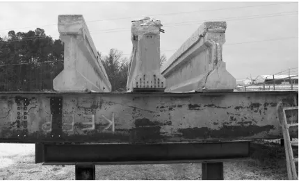
to the NCDOT Bridge Maintenance Facility in Raleigh, NC for future repair work. Figure
3.2 shows the three girders at the DOT maintenance facility. The first phase of the project
focused on repairing the severely damaged girder with rupture of one prestressing strand.
The other two structurally sound interior girders were set aside for phase two of the project,
During the first phase, the impact damaged AASHTO Type II girder previously
described was repaired using a polymer modified cementitious material to rebuild the
concrete section and CFRP wet lay-up sheets to restore the nominal section capacity. The
second phase included simulating damage to the two 55 ft (16.8 m) long specimens by
removing part of the concrete section and rupturing three or four prestressing strands,
respectively. The girders were damaged at midspan to simulate a flexurally critical situation.
The girders were then repaired in the same manner as the first AASHTO girder. Following
the completion of testing these two girders, one girder was then cut into thirds in order to
create short spans, which is typically critical for shear resistance. One of these short spans
was tested as a control specimen and the second was damaged to simulate an impact near the
girder’s support. This girder was then repaired, using PCI and ACI Committee 440 design
guidelines, and tested statically to failure. This chapter presents the experimental program
for the five test specimens. Complete test results and discussion are given in Chapter 4.
3.2 Test Girders
Three Type II AASHTO girders (AASHTO1, AASHTO2, and AASHTO3) were
tested to examine the flexural behavior of CFRP repaired girders damaged by vehicular
impact. The girders were damaged, either accidentally or artificially, near midspan location
to examine different damage scenarios, including varying the amount of prestressing strands
ruptured. This chapter will provide details and descriptions of the various tests conducted in
this study.
Two short span girders were tested under shear-critical loading conditions. Following
the flexural testing of AASHTO2, the girder was saw-cut into thirds, with the two identical
(AASHTO2C), while the other specimen was damaged near the support and repaired with
CFRP sheets (AASHTO2R). AASHTO3 was saw-cut in a similar manner and saved for
future research. This chapter will provide details and descriptions of the individual tests.
Complete test results are discussed in Chapter 4.
AASHTO1
AASHTO1 was the first girder tested in this research project. The test girder was an
AASHTO Type II girder prestressed with sixteen 0.5 in (12.7 mm) – 7 wire 270 ksi (1862
MPa) straight prestressing strands, as shown in Figure 3.3. The total length of the tested
girder was 54.84 ft (16.71 m) with a center-to-center support span of 53.34 ft (16.26 m). The
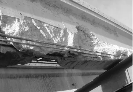
girder after impact damage from an overheight vehicle is shown in Figure 3.4. The cross
section and elevation of AASHTO1 are shown in Figure 3.3. The loss of concrete section
extended a length of 11.9 ft (3.63 m) on the front side and 6.0 ft (1.83 m) on the back side
with an approximate volume of damaged concrete equal to 4.8 ft3 (0.1 m3). In addition to the
loss of concrete, one prestressing strand on the bottom layer was ruptured on the front side,
resulting in a 6.3 percent loss of prestressing force. The full 7 ft (2.13 m) composite bridge
deck was not part of the test specimen since it was cut through in order to remove the
damaged girder from the bridge superstructure. The average width of the composite deck of
the test girder was 14.9 in (388 mm), ranging from 16.9 in (430 mm) to 13.9 in (353 mm).
Several transverse cuts were located along the length of the composite deck. These cuts,
originating during the cutting of the cast in place diaphragms, were approximately 0.4 in (10
Figure 3.4 AASHTO1 at NCDOT yard after impact damage
Design drawings provided by the NCDOT specified the 28 day concrete strength for
the girder was 5000 psi (34.5 MPa) as well as the concrete strength of the deck was 3000 psi
(20.7 MPa). Material test results of the prestressing strands and concrete core samples taken
after testing are presented in Section 3.3
AASHTO2
The second test girder, AASHTO2, was an interior girder of the bridge and therefore
was not damaged like AASHTO1. This AASHTO Type II girder was older than the others;
based on the presence of a large endblock and 28-7/16 in (11.1 mm) diameter 250 ksi (1724
MPa) prestressing strands it was determined the girder was cast in the 1960’s. The girder
down system at midspan. The total length of the girder was 54.5 ft (16.61 m), with a span
length of 53.06 ft (16.17 m) from center-to-center of the supports. Based on measurements
taken at two foot intervals, the average width of the composite deck was determined to be
16.5 in (419 mm). Cross section and elevation drawings of AASHTO2 are shown in Figure
3.5.
As previously mentioned in Section 3.1, AASHTO2 was received by the researchers
undamaged, except for several transverse cuts approximately 0.4 in (10 mm) wide in the
composite deck after the removal of the diaphragms. In order to simulate impact damage, a
large portion of the tension flange of the girder was removed (Figure 3.6), and four
prestressing strands were ruptured (Figure 3.7), corresponding to a reduction in prestressing
force of 14.3 percent. The length of the damage was extended to a total of 2.0 ft (0.61 m) on
either side of midspan on the front side of the girder only. Approximately 2.2 ft3 (0.06 m3) of
Figure 3.6 AASHTO2 during removal of concrete
Design drawings were provided by the NCDOT; however they were illegible and it
was difficult to discern most information. Initially it was assumed that the concrete strength
for the girder was 5000 psi (34.5 MPa) when it was first erected 40 some years ago. For
preliminary calculations, a girder concrete strength of 6000 psi (41.4 MPa) was used to
reflect the age of 40 years plus. The composite deck slab was estimated at 3000 psi (20.7
MPa). Material test results of the prestressing strands and concrete core samples taken after
testing girder AASHTO2 are presented in Section 3.3.
AASHTO3
The third girder tested in flexurally critical conditions was AASHTO3. This exterior
girder was an AASHTO Type II girder, but was only 10 years old because a previous girder
in the same location had been struck by an overheight vehicle and required replacement.
AASHTO3 was comprised of 16-0.5 in (12.7 mm) diameter 270 ksi (1862 MPa) straight
prestressing strands. The total length of the girder was 54.5 ft (16.61 m). The testing span
length of this girder had to be shortened to avoid the damage at one end of the girder, caused
during transportation, as shown in Figure 3.8. The center-to-center length between the
testing supports was 49.0 ft (14.94 m). Based on measurements taken at two foot intervals,
the average width of the composite deck was determined to be 13.5 in (343 mm). Cross
AASHTO3 had been impacted several times prior to being removed from the bridge.
Figure 3.10 shows one section where an earlier concrete repair had been performed along
with epoxy injection of the cracks caused by vehicular impacts. In order to simulate impact
damage to this girder, a large portion of the tension flange was removed, similar to girder
AASHTO2, and three prestressing strands were ruptured (Figure 3.11), corresponding to a
reduction in prestressing force of 18.8 percent. The length of the damage was 2.0 ft (0.61 m)
to the left of midspan and approximately 5.0 ft (1.52 m) to the right on the front side only. It
was intended for the damage to be symmetrical about midspan, but the presence of earlier
repairs made it difficult to cut as planned. A total of approximately 2.4 ft3 (0.07 m3) of
concrete was removed, as shown in Figure 3.11.
Figure 3.11 Simulated damage of AASHTO3 girder
Design drawings provided by the NCDOT indicated that the concrete strength for the
girder was 5000 psi (34.5 MPa) and 3000 psi (20.7 MPa) for the bridge deck. Material test
results of the prestressing strands and concrete core samples taken after testing girder
AASHTO3 are presented in Section 3.3.
AASHTO2C
The first girder tested during the shear study, AASHTO2C, was tested monotonically
to failure as a control specimen. The girder, shown in Figure 3.12 was prestressed with
28-7/16 in (11.1 mm) diameter 250 ksi (1724 MPa) strands. The total length of the girder was
Based on measurements taken at two foot intervals, the average width of the composite deck
was determined to be 16.5 in (419 mm). Cross section and elevation drawings of
AASHTO2C are shown in Figure 3.13.
Figure 3.13 AASHTO2C girder cross section and elevation
AASHTO2 was received by the researchers undamaged, except for several transverse
cuts which were repaired as mentioned previously in Section 3.2. Concrete strengths were
the same as those specified for girder AASHTO2. Material test results of the prestressing
AASHTO2R
AASHTO2R was tested monotonically to failure as a shear critical member with
simulated damage repaired with CFRP sheets as shown in Figure 3.14. The girder was
prestressed with 28-7/16 in (11.1 mm) diameter 250 ksi (1724 MPa) strands. The total length
of the girder was 20.67 ft (6.30 m), with a span of 17.83 ft (5.31 m) from center-to-center of
the supports. Based on measurements taken at two foot intervals, the average width of the
composite deck was determined to be 16.5 in (419 mm). Cross section and elevation
drawings of AASHTO2R, including CFRP repair details, are shown in Figure 3.15. It should
be noted that the section properties for AASHTO2R are the same as AASHTO2C but were
not included for clarity.
Figure 3.15 AASHTO2R girder cross section, elevation, and CFRP design details In order to simulate impact damage, a large portion of the tension flange of the girder
was removed, and four prestressing strands were ruptured (Figure 3.16), corresponding to a
reduction in prestressing force of 14.3 percent. The length of the damage began 1 ft (305
mm) past the face of the left support and extended 4 ft (1.22 m) to the right. A total of
Figure 3.16 AASHTO2R after completion of simulated damage
3.3 Material Properties
This section will present testing methods and results of material tests performed on
prestressing strands, concrete core samples, and CFRP sheets.
Prestressing Strands
Two different types of prestressing strands were encountered during the experimental
program of this research project. Specimens AASHTO1 and AASHTO3 utilized the same
prestressing strand pattern with 270 ksi (1862 MPa) strands, while specimens AASHTO2,
AASHTO2C, and AASHTO2R utilized the same prestressing strand pattern with 250 ksi
16-0.5 in (12.7 mm) straight prestressing strands. The 250 ksi (1724 MPa) strand pattern
(Figure 3.17 rigtht) consisted of 28-7/16 in (11.1 mm) prestressing strands, 24 of which were
straight and four of which were harped with a hold-down system located at midspan.
Material testing was carried out on prestressing strands encountered in each of the
three main girders, after testing of each girder was complete. In order to test the strands,
several were extracted from the bottom layer as close to the supports as possible. The strands
were removed from the supports to ensure the strands had not yielded under the effect of
loading. Special care was taken during removal of the strands to prevent unraveling.
Figure 3.17 270 ksi (left) and 250 ksi (right) midspan strand patterns
The prestressing strands were tested in tension according to ASTM A416
specifications using a 220 k (979 kN) MTS closed-loop universal testing machine used to
apply a constant rate of displacement. The prestressing strands were clamped into the MTS
grips using multiple-use super chucks. A 1 in (25 mm) extensometer was placed at the
middle of the specimen during the test to measure displacement and to obtain modulus of
elasticity measurements. Figure 3.18 shows a typical prestressing strand specimen. Prior to
rupture of the strand, the extensometer was removed to prevent any damage caused by the
rupture strain of the specimens. Table 3.1 shows the average yield strength, ultimate
strength, modulus of elasticity, and rupture strain for each set of tested prestressing strands.
Figure 3.18 Typical prestressing strand test setup Table 3.1 Prestressing steel properties
Specimen Designation
Strand
Type, ksi
σ
y, ksiσ
u, ksiε
u, % E, ksiAASHTO1 and AASHTO3 270 262 279 5.10 28,500
AASHTO2 250 210 255 5.62 28,900
The Ramberg-Osgood function (Collins and Mitchell 1991) was used to match the
stress-strain behavior of the prestressing strands with material constants.
(
)
[
]
⎥⎥ ⎦ ⎤ ⎢ ⎢ ⎣ ⎡ + − + = C C ps ps p p B A A E f 1 1 1 εwhere is the prestressing strand stress, is the modulus of elasticity of the prestressing
strand,
p
f Ep
ps
ε is the strain in the prestressing strand, and A,B,C are material constants.
Constants A, B, and C were determined by fitting the stress-strain curve generated by
the Ramberg-Osgood equation with the stress-strain curve generated from the tension tests.
For the 270 ksi (1862 MPa) strands, the average values for A, B, and C were 0.015, 108, and
10 respectively. These values compared well with similar test values obtained from previous
research by Rizkalla (2005). For the 250 ksi (1724 MPa), strands the average values for A,
B, and C were 0.025, 139, and 6 respectively, which also compared well with the values from
earlier research by Rizkalla (2005). Figure 3.19 shows the measured stress-strain behavior
compared to the Ramberg-Osgood function for both types of prestressing strands
encountered. 0 50 100 150 200 250 300
0 1 2 3 4 5 6
Tensile Strain (%)
Te ns il e S tres s (k si )
Ramberg - Osgood 270 ksi
Ramberg - Osgood 250 ksi
Reinforcing Bars
Due to the difficulty to extract any straight reinforcing bars, no tests were conducted
to examine the characteristics of the reinforcing bars in the deck or the stirrups of each
girder. The material properties used in the analysis were based on the specifications
provided on the design drawings provided by NCDOT.
Concrete
The specified nominal concrete strength for all of the AASHTO girders was 5000 psi
(34.5 MPa) at time of erection. The design strength of these girders, as described in Section
3.2, was estimated to increase by at least 1000 psi (6.9 MPa) as a result of the significant
aging of the concrete. The following equation proposed by MacGregor (2005) accounts for
the strength increases due to aging:
( ) ( )28
( )
' '
4 0.85
ct c
t
f f
t
⎡ ⎤
= ⎢
+
⎢ ⎥
⎣ ⎦⎥ (3.2)
where f 'c t( ) is the concrete compressive strength as a function of time and t is time in days.
Several core samples were taken from both the girders and deck slab by qualified
NCDOT personnel (Figure 3.20). The cores were then tested in accordance with ASTM C42
in an MTS closed-loop universal testing machine used to apply a constant rate of
displacement. Concrete strains were measure using the stroke of the MTS machine. Eight
inch long (203 mm) core samples were not able to be obtained due to the configuration of the
AASHTO girders. The cores taken from the deck slab were approximately 5 in (127 mm) in
length. Likewise, the only feasible place to take cores from the girder itself was from the
also cast of the various concrete repair materials used during the research. Table 3.2 lists the
average results of all concrete testing for each AASHTO girder.
Figure 3.20 NCDOT personnel removing core samples Table 3.2 AASHTO core sample test results
Specimen Designation
Compressive strength of concrete,
f’c, ksi Aggregate description
girder 7.1 Crushed and round ¼” – 1”
deck 6.7 Gritty ¼” – ½”
AASHTO1
repair mortar 6.3 N/A
girder 6.8 1” rounded quartz and river rock
deck 5.1 ½” – ¾” crushed sandstone
AASHTO2
repair mortar 6.3 3/8” crushed
girder 6.6 Crushed and round ¼” – 1”
deck 7.1 ¾” crushed
AASHTO3
Carbon Fiber Reinforced Polymers (CFRP)
Carbon Fiber Reinforced Polymer (CFRP) wet lay-up sheets were used in the repair
of every specimen, as mentioned in Section 3.1. The design of the repair systems are
presented in Section 3.4. Although several girders were repaired using the same CFRP
system, samples were made during installation and kept at the same location as the girder to
determine their tensile strength, modulus of elasticity, and rupture strain. All tests were
performed in accordance with ASTM D3039 specifications and tested using the MTS
equipment described previously in Section 3.3. Test results for each girder, along with the
manufacturer’s specifications, are shown in Table 3.3.
Table 3.3 CFRP tension test results
Specimen
Designation CFRP system
Tensile strength,
ksi E, ksi
ε
u, %Avg. thickness,
in
Test 76 6,350 1.2 .08
AASHTO1
Manufacturer 143 13,890 1.0 .04
Test 109 9,730 1.08 .096
AASHTO2 Manufacturer 143 13,890 1.0 .04
Test 109 9,730 1.08 .096
AASHTO3
Manufacturer 143 13,890 1.0 .04
Test 98 8,480 1.12 .099
AASHTO2R
Tyfo SCH-41 Composite
Manufacturer 143 13,890 1.0 .04
All CFRP samples were cut out of witness panels to a width of 1 in (25.4 mm) and a
length of 17.5 in (445 mm). The samples were then bonded to aluminum tabs using Wabo
MBrace© Saturant (Wabo 2002) to produce a gauge length of 6 in (152 mm). Figure 3.21
shows a typical CFRP tension test setup. The strain of the CFRP was measured using a
0.236 in (6 mm) TML FLA-6-11 120 Ω electric resistance strain gauge placed at the center of
the width and gauge length of the specimen. The primary mode of failure was the sudden
less frequent mode of failure, was rupturing of the CFRP matrix through the cross section, as
shown in Figure 3.22 (right).