Theory & Application of Zener Diode in Electrical & Electronics
Circuits
Jitendra singh Gurjar, JaipalGurjar, Tanujkumar,Mahendar Singh Gurjar, Sunil Nitharwal
Department of Physics, Students, B.Sc. First year, Parishkar College of Global Excellence, Jaipur
Abstract:
Zener diode –voltage regulator when it undergoes
reversed bias and a normal diode in forward bias.
Purpose to study the characteristics of zener diode
Introduction
The diode is one of the basic components
in electronic circuits When you want to know about
voltage considerations you should know about the
diodes. The diode is basically made up
of semiconductors which have two characteristics, ‘P’ type and ‘N’ type. The ‘P’type and ‘N’ type
semiconductors represent positive and negative type semiconductors. ‘P ’type semiconductor will have excess amount of holes in configuration and ‘N’
type semiconductor will have excess amount of
electrons. If both types of characteristics present in
a single crystal then it can be termed as a diode. The positive terminal of the battery connects with the ‘P’
side and the negative side is connected with the ‘N’ side. Let’s discuss about Zener diode working,
It is nothing but a simple diode connecting in
reverse bias.
Zener Diode
It is mainly a special property of the diode rather
than any special type of equipment.
The person named Clearance Zener invented this property of the diode that’s why it is named after
him as a remembrance. The special property of the
diode is that there will be a breakdown in the
circuit if the voltage applied across a reversely
biased circuit. This does not allow the current to
flow across it. When the voltage across the diode is
increased, temperature also increases and the crystal
ions vibrate with greater amplitude and all these
leads to the breakdown of the depletion layer. The
layer at the junction of ‘P’ type and ‘N’ type. When
the applied voltage exceeds an specific amount
Zener breakdown takes place.
Zener diode is nothing but a single diode connected
in a reverse bias mode and Zener diode can be
connected in reverse bias positive in a circuit as
shown as picture. We can connect it for different
applications.
The circuit symbol of Zener diode is as shown in the
figure. For convenience it is used normally. When
discussing about the diode circuits we should look
through the graphical representation of the
operation of the Zener diode. It is called the V-I
characteristics of a general p – n junction diode.
Zener Diode connection
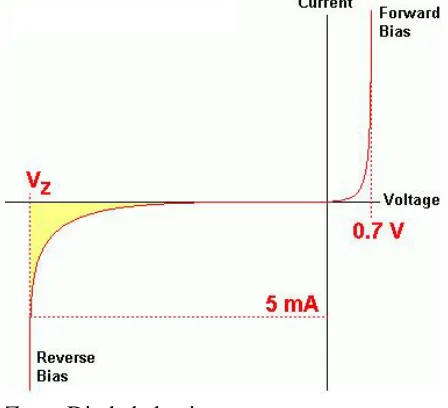
Characteristics of a Zener Diode
The above diagram shows the V-I characteristics of
the Zener diode behavior. When the diode is
connected in forward bias diode acts as a normal
diode. When the reverse bias voltage is greater than
a predetermined voltage then the Zener breakdown
voltage occurs. To get breakdown voltage sharp and
distinct doping is controlled and the surface
imperfections are avoided. In the V-I characteristics
above Vz is the Zener voltage. And also the knee
voltage because at this point the current is the
current is very rapid.
Zener Diode behavior
Application of Zener Diode
Zener diode is popularly used as Shunt Regulator or
Voltage Regulator. As we have gone through the
first part of the article we know what Zener diode is
and what the basic principle of operation is. Here
the question arises where this type of diodes can be
useful. Main application of this type of diodes are as
voltage regulator. Over voltage protector, as voltage
Zener Diode checking
We have discussed the application of Zener diode as
voltage regulator and now we will discuss the other
two points.
Over voltage protection is done by using Zener
diodes because there is current flowing through the
diode after the reverse bias voltage exceeds a certain
voltage . This circuit provides safety for the
equipment connected at the terminals. Normally the
current should not exceed normal valve but if due to
any fault in the circuit the current exceeds the
maximum allowable voltage, then the equipment of
the system can be damaged. A SCR is used, by it the
output voltage is quickly cut down and a fuse blows
which disconnects the input source power. The
circuit arrangement is shown below for better
understanding,
Zener Diode connection
Voltage reference determines the constant supply of
power current or voltage as the Zener voltage
works. If the supply of current is same then to avoid
unstable performance we use Zener diodes. These
are used where voltage reference is required like
ammeters, ohmmeters and voltmeters.
Zener Diode as Voltage Regulator
The term regulator means which regulates. The
Zener diode can work as a voltage regulator if it is
introduced in a circuit. The output across the diode
will be constant. It is driven by a current source. As
we know if the voltage across the diode exceeds a
certain value it would draw excessive current from
the supply. The basic diagram of Zener diode as
voltage regulator is given below,
To fix the current through the Zener diode series
resistance R is introduced whose value can be
chosen from the following equation
Resistor value (ohms) = (V1 – V2) / (Zener current
+ load current)
The above diagram is of a shunt regulators because
the regulating element is parallel to the load
element. The Zener diode produces a stable
reference voltage across the load which fulfills the
The Zener diode allows current to flow in the
forward direction in the same manner as an ideal
diode. It also permits to flow in the reverse
direction when the voltage is above a certain value
known as breakdown voltage.
This device is named after Zener. Zener discovered
this electrical property. A Zener diode is one in
which the reverse breakdown occurs due to electron
quantum tunneling under high electric field strength
called Zener effect. Many diodes described as Zener
diodes rely instead on avalanche breakdown. Both
types are used with the Zener effect predominating
under 5.6 V and avalanche breakdown above.
Regular applications include providing a reference
voltage for voltage regulators. This is to protect
devices from momentary voltage pulses.
Zener Diode Connectivity
These devices are also encountered in series with a
base emitter junction. At transistor stages where
selective choice of a device centered around the
avalanche or Zener point. It can be used to introduce
compensating temperature coefficient balancing of
the transistor . DC error amplifier used in a
regulated power supply circuit feedback loop
system is the on of the example.
These are also used in surge protectors to limit
transient voltage spike systems and another
application of the Zener diode is the use of noise
caused by its avalanche breakdown in a random
number generator.
Conclusion:
.Zener diodes are designed to operate at voltages greater than the breakdown voltage (peak reverse voltage).
● The breakdown voltage of a zener diode is deter- mined by the resistivity of the diode.
● Zener diodes are manufactured with a specific breakdown (zener) voltage.
● Power dissipation of a zener diode is based on temperature and lead lengths.
● Zener diodes are packaged the same as P–N junction diodes.
● Zener diodes with a breakdown voltage greater than 5 V have a positive zener voltage- temperature coefficient.
● Zener diodes with a breakdown voltage less than 4 V have a negative zener voltage temperature coefficient.
● Zener diodes are used to stabilize or regulate voltage.
● Zener diode regulators provide a constant output voltage despite changes in the input voltage or output current.
● Zener diodes can be tested for opens, shorts, or leakage with an ohmmeter.
● To determine whether a zener diode is regulat- ing at the proper voltage, a regulation test must be performed.
1. Milkman, Jacob (1979). Microelectronics. McGraw Hill. pp. 45–48. ISBN 978-0071005968.
2. Dorf, Richard C., ed. (1993). The Electrical Engineering Handbook. Boca Raton: CRC Press. p. 457. ISBN 0-8493-0185-8.
3. Calibration: Philosophy in Practice. Fluke. 1994. pp. 7–10. ISBN 0963865005.