Available online:
https://edupediapublications.org/journals/index.php/IJR/
P a g e | 1767Improving Productivity And Quality By Changing Feeding System In An
Injection Moulding Process
Padamgalla Swapna & Sri G. Gopi Nath.
M.Tech in Advanced Manufacturing Systems from Ellenki college of Engineering and Technology, JNTU, Hyderabad, Telangana, India
Assistant professor, Ellenki college of Engineering and Technology, JNTU, Hyderabad, Telangana, India
ABSTRACT
In this thesis, the feeding system for a plastic product is optimized to improve the productivity as well as the quality. A fan blade back cover is designed and modeled in 3D modeling software Creo 2.0. The process parameters considered in three cases, Case-1: Max Injection Pressure: 180MPa, Mold Temperature: 40 deg C, Melt Temperature: 300 deg C, Case-2: Max Injection Pressure: 260MPa, Mold Temperature: 60 deg C, Melt Temperature: 300 deg C and Case-3:
Max Injection Pressure: 340MPa, Mold Temperature: 80 deg C, Melt Temperature: 300 deg C. The material is Polypropylene. A repeated number of analyses are carried out by plastic flow advisor which is a module in pro/Engineer software to reduce fill time, scrap and automatic degating by taking single gate and two gates using material Polypropylene. The parameters like fill time, shrinkage, weld lines, pressure drop, and air traps are analyzed by simulation in successive trials.
INTRODUCTION TO INJECTION
MOULDING
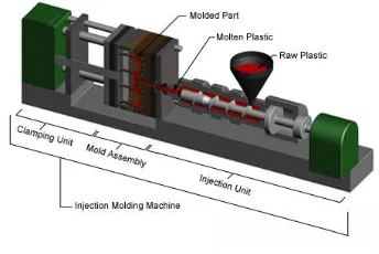
The fabrication of plastic components is done by using Injection molding manufacturing process. Utilizing injection molding a large variety of plastic products is manufactured, that vary greatly in their complexity, size, and application. The injection molding method needs the utilization of an injection molding machine, raw plastic material, and a mold. The plastic is melted within the injection molding machine and
so injected into the mold, where it cools and solidifies into the ultimate part.
Fig – Injection Molding Machine
PROCESS CYCLE
The process cycle for injection molding is very short, typically between 2 seconds and 2 minutes, and consists of the following four stages:
1. Clamping – the mold two halves core & cavity need to be closed securely by the clamping unit prior to the material injection into the mold.
2. Injection – commonly in the pellets form the raw plastic material, is fed into the injection molding machine, and advanced towards the mold by the injection unit. Throughout this method, the material is melted by heat and pressure.
Available online:
https://edupediapublications.org/journals/index.php/IJR/
P a g e | 1768surfaces. As the plastic cools, it'll solidify
into the form of the component desired. However, throughout cooling some shrinkage of the part could occur.
4. Ejection - After ample time has passed, using the ejection system the cooled part is ejected from the mold that is hooked up to the rear half of the mold. A mechanism is employed to push the part out of the mold once the mold is opened. The part shrinks and adheres to the mold during cooling so to eject the part force should be applied. The time that's needed to mold opening and part ejecting is often calculable from the dry cycle time of the machine and may embrace time for the part to fall freed from the mold.
MATERIALS
There are many varieties of materials that will be utilized in the injection molding process most polymers are utilized, including all thermoplastics, some elastomers and some thermosets. The raw material to be utilized in the injection molding process is of typically tiny pellets or fine powder. Also, to give the desired color to the final product colorants are added. The material choice for making injection molded components isn't only based mostly upon the specified characteristics of the ultimate part. Whereas each material has totally different properties that may have an effect on the function and strength of the ultimate component, these properties conjointly dictate the parameters utilized in processing these materials. A unique set of process parameters are needed for each material within the injection molding method including injection pressure, mold temperature, injection temperature, cycle time and ejection temperature.
DESIGN OF GATE LOCATIONS
Each injection mould design should have a gate, or an opening that permits the molten plastic to be injected into the mould cavity. Gate type,
design and placement will have effects on the component like gate removal or vestige, cosmetic look of the part, part dimensions & warping and part packing.
Fig - Design of gate locations
INJECTION MOLDING PROCESS
CONDITIONS
Injection moulding is an engineering technology, it's associated with the contents of the plastic into helpful and might maintain the initial performance of the products. The injection molding process conditions importance have an effect on the plastics flow and cooling the temperature, pressure and also the corresponding time for each role.
1. Temperature control
Mold Temperature 2. Pressure control
Plasticizing Pressure
Injection Pressure
PLASTC ADVISOR
Plastic advisor is an add on analysis package for Pro/Engineer, especially for plastic injection moulding.
Results to be observed from analysis are 1) Plastic flow
2) Fill time
3) Confidence of fill 4) Injection pressure 5) Pressure drop
Available online:
https://edupediapublications.org/journals/index.php/IJR/
P a g e | 17697) Quality prediction
8) Weld lines and air traps.
LITERATURE SURVEY
The Paper work done by Lam, Y.C., Jin, S.[1], developed an automated routine to handle design constraints in automated gating synthesis, taking functionality advantages of both CAD and CAE systems. Variance of filling time is employed as the objective function and hill-climbing search algorithmic program is utilized throughout the gate optimisation method. Design constraints thought-about to date are no-gate constraints for 3 plate moulded part and edge-gate constraints for 2 plate moulded part. These constraints are outlined in an Integrated design environment of CAD/CAE for plastic injection molding utilizing the CAD system functionality, and so translated into CAE options. The Paper work done by Sahputra, I.H. [2], Main objective of this paper is to debate comparison of the results of injection moulding method, particular software generating the simulation analysis generated with those obtained in a small-scale industrial process. The samples were made by 'Dausset'
injection moulding machine at laboratory. Part was modeled utilizing Rhinoceros Computer Aided Design (CAD) software. Utilizing Mould Flow Plastics Insight (MPI) simulation analysis was performed. 2 completely different positions of gate were selected for simulation to research the software accuracy. High impact polystyrene (HIPS) and Polyethylene (PE) were selected for analysis and production.
3D MODELING OF FAN BLADE BACK COVER IN CREO 2.0
Fig: Fan Blade Back cover
INPUT PARAMETERS
Material - Polypropylene
Gate locations are single gate and two gates
CASE-1 CASE-2 CASE-3
Injection Pressure (MPa) 180 40 300
Mold Temperature (0C) 260 60 300
Melt Temperature (0C) 340 80 300
MOULD FLOW ANALYSIS
2 GATES
CASE-3
Available online:
https://edupediapublications.org/journals/index.php/IJR/
P a g e | 1770Release Level: 7.0
point1
Part Name: point1 Part Revision: 1 Material Supplier: Generic
Material Grade: PP, High-flow - Polypropylene Max Injection Pressure: 240.00 MPa
Mold Temperature: 60.00 deg.C Melt Temperature: 260.00 deg.C
Model Suitability: Part model was highly suitable for analysis.
Filling Analysis point1
Moldability: Your part can be easily filled.Part quality will be acceptable.
Confidence: Medium Injection Time: 16.53 sec Injection Pressure: 0.34 MPa Weld Lines: Yes Air Traps: Yes
Shot Volume : 413.65 cu.cm Filling Clamp Force: 0.23 tonne
Packing Clamp Force Estimate @20%: ( 0.07 )MPa 0.08 tonne Packing Clamp Force Estimate @80%: ( 0.27 )MPa 0.32 tonne Packing Clamp Force Estimate
@120%: ( 0.41 )MPa 0.47 tonne Clamp Force Area: 113.46 sq.cm
Cycle Time: 511.46 sec
Cooling Quality point1
Solver Warning Mold surface temperature specified is outside the recommended range for the specified material.
Cooling Quality: Your part has some small problems and may not cool satisfactorily. Surface Temperature
Variance Range -6.87 deg.C to 9.41 deg.C Freeze Time Variance Range -23.81 sec to 51.34 sec
Sink Mark Analysis point1
Available online:
https://edupediapublications.org/journals/index.php/IJR/
P a g e | 1771Glass Model
Fill Time
Confidence of Fill
Available online:
https://edupediapublications.org/journals/index.php/IJR/
P a g e | 1772Pressure Drop
Flow Front Temp.
Quality Prediction
Available online:
https://edupediapublications.org/journals/index.php/IJR/
P a g e | 1773Weld Lines
Air Traps
Cooling Quality
Sink Marks Estimate
Available online:
https://edupediapublications.org/journals/index.php/IJR/
P a g e | 1774RESULTS TABLE
SINGLE GATE
CASE 1 CASE 2 CASE 3
Confidence MEDIUM MEDIUM MEDIUM
Fill Time
(Secs) 18.42 19.43 16.40
Injection Pressure (Mpa) 0.58 0.63 0.44
Pressure Drop (Mpa) 0.58 0.63 0.44
Flow Front Temp 230 220 260
Weld Lines YES YES YES
Air Traps YES YES YES
Cycle Time (Secs) 484.23 468.45 525.44
Quality Prediction HIGH HIGH HIGH
Sink Marks
8 % of your model was found
to be prone to sink marks.
8 % of your model was found
to be prone to sink marks.
8 % of your model was found
to be prone to sink marks.
TWO GATES
CASE 1 CASE 2 CASE 3
Confidence MEDIUM MEDIUM MEDIUM
Fill Time (Secs) 18.60 20.63 16.53
Injection Pressure
(MPa) 0.44 0.47 0.34
Pressure Drop
(Mpa) 0.44 0.47 0.34
Flow Front Temp 230 220 260
Weld Lines YES YES YES
Air Traps YES YES YES
Cycle Time (Secs) 463.73 446.77 511.46
Quality Prediction HIGH HIGH HIGH
Sink Marks
8 % of your model was found to be prone to sink marks.
8 % of your model was found to be prone to sink
marks.
8 % of your model was found to be prone to sink
Available online:
https://edupediapublications.org/journals/index.php/IJR/
P a g e | 1775CONCLUSION
By observing the analysis results, use of two gates reduces the total cycle time but the fill time is more when compared with that of single gate. The total cycle time less for the case 2 (i.e) when the max. injection pressure taken is 260MPa, Mold Temperature taken is 600C. The flow temperature is within the recommended temperature range for the material used so material degradation and surface defects do not occur.
REFERENCES
[1] Plastic Injection Molding: Manufacturing Process Fundamentals by Douglas M. Bryce [2] Injection Mould Design: A Design Manual for the Thermoplastics Industry by R G W Pye
[3] The Mould Design Guide by Peter Jones [4] Injection molding - Society of Plastics Engineers
[5] Injection moulding of plastic components by John Bown
0 5 10 15 20 25
CASE 1 CASE 2 CASE 3
FI LL T IM E (Sec s) CASES
COMPARISON OF FILL TIME FOR SINGLE AND TWO
GATES AT DIFFERENT CASES
SINGLE GATE TWO GATES 400 420 440 460 480 500 520 540
CASE 1 CASE 2 CASE 3
C Y C LE T IM E (Sec s) CASES
COMPARISON OF CYCLE TIME FOR SINGLE AND
TWO GATES AT DIFFERENT CASES
SINGLE GATE
Available online:
https://edupediapublications.org/journals/index.php/IJR/
P a g e | 1776[6] Rosato, D. Injection Moulding
Handbook. Second Edition, Chapman & Hall, London, 1995.
[7] Lam, Y.C., Jin, S. Optimization of the gate location for plastic injection moulding. Journal of Injection Moulding Technology, 2001
[8] Sahputra, I.H. Comparison of two flow analysis software for injection moulding tool design. Proceedings of the International Conference on Industrial Engineering and Engineering Management, 2-4 Dec. 2007, Singapore.
[9] Saman, A.M., Abdullah, A.H., Nor, M.A.M. Computer simulation opportunity in plastic injection mould development for automotive part. International Conference on ComputerTechnology and Development, 13-15 Nov. 2009, Kota Kinabalu, Malaysia