Scholarship@Western
Scholarship@Western
Electronic Thesis and Dissertation Repository
9-29-2015 12:00 AM
Design, Implementation, and Verification of a Reactor Protection
Design, Implementation, and Verification of a Reactor Protection
System Using HFC6000
System Using HFC6000
Michael V. Gverzdys
The University of Western Ontario
Supervisor Jin Jiang
The University of Western Ontario
Graduate Program in Electrical and Computer Engineering
A thesis submitted in partial fulfillment of the requirements for the degree in Master of Engineering Science
© Michael V. Gverzdys 2015
Follow this and additional works at: https://ir.lib.uwo.ca/etd
Recommended Citation Recommended Citation
Gverzdys, Michael V., "Design, Implementation, and Verification of a Reactor Protection System Using HFC6000" (2015). Electronic Thesis and Dissertation Repository. 3317.
https://ir.lib.uwo.ca/etd/3317
This Dissertation/Thesis is brought to you for free and open access by Scholarship@Western. It has been accepted for inclusion in Electronic Thesis and Dissertation Repository by an authorized administrator of
DESIGN, IMPLEMENTATION, AND VERIFICATION OF A REACTOR PROTECTION SYSTEM FOR NUCLEAR POWER PLANT USING HFC6000
(Thesis format: Monograph)
by
Michael Victor Gverzdys
Graduate Program in Electrical and Computer Engineering
A thesis submitted in partial fulfillment of the requirements for the degree of
Master of Engineering Science
The School of Graduate and Postdoctoral Studies The University of Western Ontario
London, Ontario, Canada
Abstract
Recently, a nuclear power plant physical simulator to support instrumentation and control (I&C) research has been constructed at the University of Western Ontario using industry-grade sensors and actuators. This platform, known as the Nuclear Power Control Test Facility (NPCTF), provides means to safely inject faults and examine their effects on the system. The NPCTF may be configured into a number of nuclear power plant (NPP) types, but focus has been placed on CANadian Deuterium Uranium (CANDU) type. In a CANDU based NPP, there are two independent and separated systems with decision-making units capable of actuating two shutdown systems. These units form the reactor protection system, and monitor critical system variables to ensure that they remain within safe operating limits.
For this work, in ongoing efforts to further improve the fidelity of the NPCTF, a dedicated reactor protection system has been realized. This system has been implemented through a United States Nuclear Regulatory Commision certified safety programmable logic controller (PLC), known as the HFC6000. This has been integrated with the NPCTF through a standard industrial interface, and performs monitoring functions and decision logic operations. The reactor protection system responds to contingencies by issuing trip signals to perform safety shutdown actions.
The designed system has undergone a full verification and validation (V&V) process. Nine CNSC design basis events have been considered under full-system testing, including the loss-of-coolant-accident and loss-of-reactor-control. The designed logic achieved a 100% success rate on 25 trials. Further, the implemented system produced no spurious trips during normal operations.
The relationship between CANDU type NPPs and the NPCTF has been established. The work has also concluded that the NPCTF is capable of replicating dynamic relationships among different variables in an NPP. Through V&V tests, , the designed logic, and implemented system using HFC6000 have been proven to be successful according to the safety system criteria from the Canadian Nuclear Safety Commission.
Key Words: Physical Simulation, Safety Systems, V&V, PLC, Shutdown Systems, Reactor
Acknowledgements
I wish to express sincere appreciation to my thesis supervisor, Dr. Jin Jiang. Without his guidance, expertise, patience, and dedication, this work would not have been possible. His leadership and inspiration have been essential in my studies. I would further like to thank Dr. Xinhong Huang for her support, friendship, and commitment to our research team.
Special thanks to HFControls for donation of their system. Sincere appreciation is given to Thom Shaefer, who gifted me countless hours of his time supporting this project. His humour and expertise shed light on my most frustrating hours.
I have deep gratitude to the UWO CIES team. Their endless support, both technical and non-technical, have been invaluable to me over the past two years. Elizabeth K.M. Tomaszewski, Devbratta Thakur, Syed A. Raza, and the entire team made my time during my master’s work a deeply enjoyable and rewarding experience.
I could not have done this without those closest to me: my mother and father, Ingrid Thie and Sharunas Gverzdys, for their love, encouragement, and inexhaustible belief in me; Ariana and Marcus Gverzdys for celebrating my successes and relieving my disappointments in equal parts with humour; and Andrée Chartrand for her endless support, kindness, and grace. In particular, recognition is given to Tomas Gverzdys, who taught me to love science, pursue knowledge, and follow my dreams.
Table of Contents
Abstract ... ii
Acknowledgements ... iii
Table of Contents ... iv
List of Tables ... x
List of Figures ... xiii
List of Appendices ... xvii
List of Abbreviations ... xviii
Symbols and Nomenclature ... xx
1 Introduction ... 1
1.1 NPP Basics ... 1
1.2 Safety Systems ... 3
1.3 Nuclear Control and Safety Commissions ... 5
1.3.1 Testing for Nuclear Applications ... 7
1.3.2 Differences between Physical and Software Models ... 8
1.4 Research Objectives and Scope... 9
1.4.1 Objectives ... 9
1.4.2 Scope ... 10
1.4.3 Solution Technique ... 11
1.5 Contributions of the Thesis ... 12
1.7 Organization of the Thesis ... 13
2 Literature Review... 14
2.1 CANDU Reactor ... 14
2.1.1 Heavy Water Moderator ... 14
2.1.2 Neutron Economy ... 16
2.2 Reactor Protection Systems: Overview ... 19
2.2.1 Shutdown Systems 1 and 2 ... 20
2.2.2 Safety Systems ... 23
2.3 Design Methods of Reactor Protection Systems ... 24
2.3.1 Key Monitoring Parameters ... 24
2.3.2 Redundancy... 27
2.3.3 Diversity of Design ... 28
2.4 CANDU Shutdown Logic ... 30
2.5 Trip Set-point Determination ... 31
2.5.1 Uncertainty Measurements and Calculations... 33
2.5.2 Methodologies without Design Basis Events ... 34
2.6 Best Estimate and Uncertainty Analysis ... 36
2.7 Testing and V&V Methods ... 40
2.7.1 Canadian Requirements ... 41
2.7.3 IEEE Std. 1012... 44
2.8 Safety PLC ... 45
2.9 Chapter Summary ... 48
3 Cross-Comparison of NPCTF and CANDU NPP Signals ... 50
3.1 NPCTF Overview ... 50
3.1.1 Comparison of CANDU NPP and NPCTF Parameters ... 53
3.2 Key Operating Parameters on NPCTF ... 55
3.2.1 Primary Loop Pressure ... 57
3.2.2 Pressurizer Level ... 58
3.2.3 Primary Water Flow ... 60
3.2.4 HX Tank Pressure ... 61
3.2.5 Heater Outlet Temperature ... 62
3.2.6 HX Tank Level ... 65
3.3 Chapter Summary ... 67
4 Implementation of Reactor Protection Systems Using HFC6000 ... 69
4.1 Overview of HFC6000 ... 69
4.1.1 The SBC06 Processor Board ... 71
4.1.2 The I/O Cards ... 73
4.1.3 Engineering Workstation (EWS) ... 73
4.2.1 Primary Line Flow (F1) ... 76
4.2.2 Primary Line Pressure (P1) ... 78
4.2.3 HX Tank Pressure (P2) ... 82
4.2.4 Pressurizer Tank Level (L3) ... 86
4.3 Description of Implemented Monitoring Software ... 90
4.3.1 Algorithm Overview ... 91
4.3.2 Start-Up Procedure... 93
4.3.3 Boundary Procedure... 95
4.3.4 Heater Current (C2) Tracking ... 96
4.3.5 Heat Transition Algorithm ... 97
4.3.6 Level Transition Algorithm (Up) ... 100
4.3.7 Level Transition Algorithm (Down) ... 101
4.4 Overall System Diagram ... 103
4.5 MATLAB Simulation of Developed Software on NPCTF Operations ... 105
4.6 Theoretical Shutdown Time ... 109
4.7 Chapter Summary ... 110
5 Verification and Validation... 111
5.1 Summary of Tests Performed ... 111
5.2 Verification Tests ... 112
5.2.2 HFC-6000 Response Testing ... 113
5.3 AECB Standard Scenarios ... 114
5.4 Systems Testing and Simulated Faults ... 116
5.4.1 Normal Operations ... 117
5.4.2 Fault Insertion Methodology... 118
5.4.3 The Faults... 121
5.5 Experiment 1: Normal Operating Conditions ... 131
5.5.1 Heater-Independent Parameters ... 131
5.5.2 Heater-Dependent Parameters ... 136
5.6 Experiment 2: Fault Insertion ... 140
5.6.1 Fault A: Heater Current Failure ... 141
5.6.2 Fault B: Pump1 Failure ... 143
5.6.3 Fault C: CV-3 Open ... 144
5.6.4 Fault D: LOCA ... 146
5.6.5 Fault E: CV-20 Force Open ... 148
5.6.6 Fault F: CV-18: Force Open ... 149
5.6.7 Fault G: Pump3 Failure ... 150
5.6.8 Fault H: CV-1 & CV-2 Force Close ... 151
5.6.9 Fault I: CV-9 Open/CV-10 Force Close ... 152
6 Conclusions ... 156
6.1 Summary ... 156
6.2 Conclusions ... 157
6.3 Future Work ... 158
7 References ... 159
List of Tables
Table 2.1: Effectiveness of Common Moderators. ... 16
Table 2.2: Common CANDU Safety Parameters. ... 25
Table 2.3: NPCTF Equivalent Signals. ... 25
Table 2.4: Common CANDU Safety Parameters. ... 26
Table 2.5: IEEE Std. 1012 Process Steps. ... 45
Table 2.6: Safety Integrity Levels ... 47
Table 3.1: Comparison of Major Features between CANDU and NPCTF. ... 53
Table 3.2: Parallel Parameters between CANDU Shutdown Systems and the NPCTF. ... 56
Table 3.3: Maximum and Minimum Values of Primary Pressure Related to NPCTF Operating Point. ... 58
Table 3.4: Maximum and Minimum Values of Pressurizer Water Level Compared to Heater Operating Points... 59
Table 3.5: Flow Rate in Relation to Heater Set Point ... 61
Table 3.6: HX Tank Pressure vs. Heater Operating Point. ... 61
Table 3.7: Actual Heater Temperatures at Operating Points. ... 63
Table 3.8: Transition Times for Heater Outlet Temperature. ... 63
Table 3.9: The HX Tank Level Operating Points Related to Heater Outlet Temperature Operating Point. ... 66
Table 3.10: Maximum Transition Times for HX Tank Level. ... 67
Table 4.2: Breaching Characteristics of Primary Flow Rate as a Function of Lower Boundary
Point. ... 76
Table 4.3: Breaching Characteristics of Primary Line Pressure as a Function of Lower Boundary Point. ... 79
Table 4.4: Breaching Characteristics of Primary Line Pressure as a Function of Upper Boundary Point. ... 80
Table 4.5: Breaching Characteristics of HX Tank Pressure as a Function of Lower Boundary Point. ... 83
Table 4.6: Breaching Characteristics of HX Tank Pressure as a Function of Upper Boundary Point. ... 85
Table 4.7: Breaching Characteristics of Pressurizer Tank Level as a Function of Lower Boundary Point. ... 87
Table 4.8: Breaching Characteristics of Pressurizer Tank Level as a Function of Upper Boundary Point. ... 89
Table 5.1: HFC to NPCTF Readings. ... 113
Table 5.2: Replica of Table 1 of AECB R-8. ... 115
Table 5.3: States of Operation. ... 118
Table 5.4: NPCTF Equivalents to AECB Design Events. ... 119
Table 5.5: Faults Inserted as Part of System Validation. ... 120
Table 5.6: Organization of Fault Insertion. ... 121
Table 5.7: Transition Times and Maximum Permitted for Temperature in Heater During Normal Operations Conditions. ... 138
Table 5.9: Trigger Parameter by Fault and Operating Point ... 141
List of Figures
Figure 1.1: Configuration of a CANDU NPP ... 4
Figure 1.2: Thesis Workflow ... 11
Figure 2.1: Control of a Nuclear Power Plant... 20
Figure 2.2: CANDU Shutdown Systems ... 22
Figure 2.3: CANDU Shutdown Logic ... 30
Figure 2.4: Definition of Margins in a Nuclear Power Plant. ... 32
Figure 2.5: Simplified V&V Diagram ... 43
Figure 2.6: CANDU Shutdown Systems Control ... 46
Figure 3.1: The NPCTF Schematic. ... 51
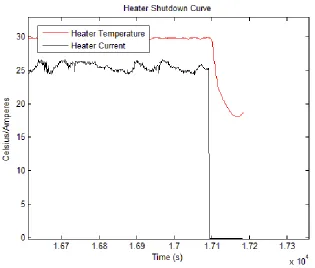
Figure 3.2: Typical Shutdown Curves of a Nuclear Reactor. ... 55
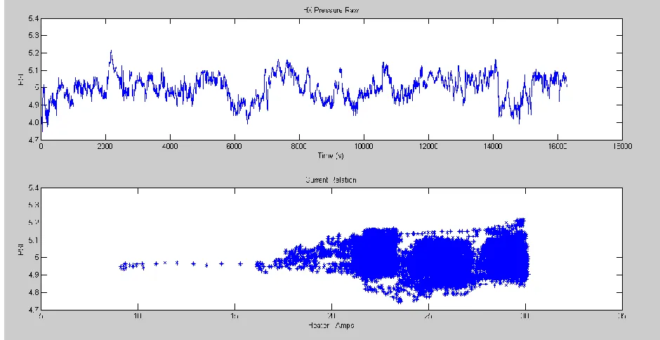
Figure 3.3: The Current Drop of NPCTF... 55
Figure 3.4: Operating Characteristics of Primary Pressure. ... 57
Figure 3.5: Operating Characteristics of Pressurizer Level. ... 59
Figure 3.6: Example of Flow Characteristics of Primary Loop. ... 60
Figure 3.7: Example of Operating Characteristics of HX Tank Pressure. ... 62
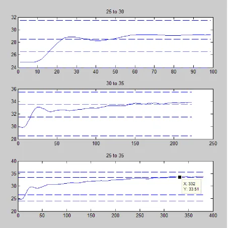
Figure 3.8: Demonstration of Transition Steps between Heater Outlet Set Points. ... 64
Figure 3.9: Swell and Shrink in HX Tank. ... 66
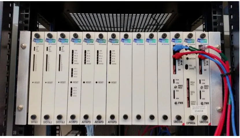
Figure 4.1: HFC6000 Front Pane ... 69
Figure 4.3: Characteristics of Primary Flow Rate in Healthy and Faulty Operating States. .. 78
Figure 4.4: Breaching Characteristics of Primary Line Pressure as a Function of Lower
Boundary Point. ... 79
Figure 4.5: Breaching Characteristics of Primary Line Pressure as a Function of Upper
Boundary Point. ... 81
Figure 4.6: Characteristics of Primary Pressure in Healthy and Faulty Operating States. ... 82
Figure 4.7: Breaching Characteristics of HX Tank Pressure as a Function of Lower Boundary
Point. ... 84
Figure 4.8: Breaching Characteristics of HX Tank Pressure as a Function of Upper Boundary
Point. ... 85
Figure 4.9: Characteristics of HX Tank Pressure in Healthy and Faulty Operating States. ... 86
Figure 4.10: Breaching Characteristics of Pressurizer Tank Level as a Function of Lower
Boundary Point. ... 88
Figure 4.11: Breaching Characteristics of Pressurizer Tank Level as a Function of Upper
Boundary Point. ... 89
Figure 4.12: Characteristics of Pressurizer Level in Healthy and Faulty Operating States. ... 90
Figure 4.13: Overview of Safety Algorithm. ... 92
Figure 4.14: Functional Block Diagram of Start-Up Procedures. ... 94
Figure 4.15: Functional Block Diagram of Boundary Checking Procedure. ... 95
Figure 4.16: Functional Block Diagram of Current Tracking Program within Safety Algorithm.
... 96
Figure 4.17: Functional Block Diagram of Heat Transition Program within Safety Algorithm.
Figure 4.18: Functional Block Diagram of Level Transition (Up) Program within Safety
Algorithm. ... 100
Figure 4.19: Functional Block Diagram of Level Transition (Down) Program within Safety Algorithm. ... 102
Figure 4.20: HFC and NPCTF Hardware/Software Logical Diagram ... 104
Figure 4.21. Theoretical Boundary Evaluation during Transition ... 106
Figure 4.22: Level Transition Flags Simulation. ... 107
Figure 4.23: Sudden Drop in Heater Temperature. ... 108
Figure 5.1: Schematic for Pump1 Failure. ... 123
Figure 5.2: Schematic for Fault C: CV-3 Force Open. ... 124
Figure 5.3: Schematic for Fault D: LOCA... 125
Figure 5.4: Schematic for Fault E: CV-20 Force Open. ... 126
Figure 5.5: Schematic for Fault F: CV-18 Force Open. ... 127
Figure 5.6: Schematic for Fault G: Pump3 Failure. ... 128
Figure 5.7: Schematic for Fault H: CV-1 and CV-2 Force Close. ... 129
Figure 5.8: Schematic for Fault I: CV-9 Open/CV-10 Close. ... 130
Figure 5.9: Primary Pressure vs. Heater Current. ... 132
Figure 5.10: Timeline of Primary Pressure during Normal Conditions Experiments. ... 133
Figure 5.11: Operations of HX Tank Pressure... 134
Figure 5.13: Breaching Characteristics Flow Rate Lower Boundary during Normal Conditions
Experiments. ... 136
Figure 5.14: The Heat Boundary vs. Heater Temperature for First Normal Operations Experiment. ... 137
Figure 5.15: Level Boundary vs. HX Tank Level for First Normal Operating Conditions Experiment. ... 139
Figure 5.16: Result of Fault A when inserted during 35⁰C25⁰C Transition. ... 142
Figure 5.17: Result of Fault B when inserted during 25⁰C35⁰C Transition. ... 143
Figure 5.18: Result of Fault C when inserted during 25⁰C35⁰C Transition. ... 145
Figure 5.19: Result of Fault C when inserted during 35⁰C30⁰C Transition. ... 146
Figure 5.20: Result of Fault D when inserted during 30⁰C Operating Point. ... 147
Figure 5.21: Result of Fault D when inserted during 25⁰C35⁰C Transition. ... 148
Figure 5.22: Result of Fault E when inserted during 25⁰C30⁰C Transition. ... 149
Figure 5.23: Result of Fault F when inserted during 35⁰C 25⁰C Transition. ... 150
Figure 5.24: Result of Fault G when inserted during 35⁰C30⁰C Transition. ... 151
Figure 5.25: Result of Fault H when inserted during 30⁰C25⁰C Transition. ... 152
List of Appendices
Appendix A: Matlab Code ……….…………167
Appendix B: HFC Code………..…180
List of Abbreviations
2oo3 2 out of 3
AECB Atomic Energy Control Board
C-Link Communication Link
CANDU CANadian Deuterium Uranium
CCF Common Cause Failure
CNSC Canadian Nuclear Safety Commission
DCS Distributed Control System
DPM Dual Port Memory
EE Equations Editor
EWS Engineering Work Station
FMEA Failure Mode Effect Analysis
HIL Hardware In the Loop
HFC HFC6000 Nuclear Safety PLC
HX Heat eXchanger
I&C Instrumentation and Control
ICL Inter-Communication Link
IEC International Electrotechnical Commission
IEEE Institute of Electrical and Electronics Engineers
I/O Input/Output
IRC Inverse Response Characteristic
ISO International Organization for Standardization
LOCA Loss Of Coolant Accident
NPEC Nuclear Power Engineering Committee
NPP Nuclear Power Plant
PDC Programmable Digital Comparator
PES Power Engineering Society
PHA Preliminary Hazard Analysis
PLC Programmable Logic Controller
SDS1 Shutdown System 1
SDS2 Shutdown System 2
SPICE Software Process Improvement and Capability dEtermination
SYS HFC SYStems processor
USNRC United States Nuclear Regulatory Commission
UWO University of Western Ontario
Symbols and Nomenclature
𝑴𝑹 Moderating Ratio
𝝃 Average Log Energy Decrement
𝝈𝒔 Scattering Cross Section
𝝈𝒂 Absorption Cross Section
𝑬𝐡𝒊𝒈𝐡 Initial Neutron Energy
𝑬𝒍𝒐𝒘 Required Neutron Energy
𝑵 Average Collisions Required
𝑷 Power of Reactor
𝑬𝑹 Energy Released in Fission
𝑵𝒅 Fissile Density Number
𝝈𝒇 Atomic Cross Section
𝝓 Instantaneous Neutron Flux
𝑽 Volume of Reactor
𝑬𝒊𝒏𝒄𝒐𝒎𝒊𝒏𝒈 Neutron Energy before Collision
𝑬𝒔𝒄𝒂𝒕𝒕𝒆𝒓𝒆𝒅 Neutron Energy after Collision
𝒌𝒆𝒙 Excess Multiplication Factor
𝒌𝒆𝒇𝒇 Effective Multiplication Factor
𝝆 Reactivity
𝑨 Atomic Mass
C2 Heater Current
T2 Heater Outlet Temperature
L4 HX Tank Water Level
P1 Primary Loop Pressure
P2 HX Tank Pressure
F1 Primary Loop Flow Rate
CV Control Valve
1
Introduction
Nuclear power plants (NPP) have a proven capability to produce reliable and clean power
in large quantities. However, because both the energy density in the fuel in an NPP and its
radioactive by-products, NPPs present an inherent risk in their operations. For these reasons
the nuclear industry not only possesses a plethora of governing bodies and regulations, but
treats safety as top priority during all phases of an NPP’s lifespan. The ultimate foal of NPP
safety is to prevent radiological releases [1]. Thus, safety continues to be an area of continual
research and improvement within the industry.
A physical NPP simulator to support instrumentation and control (I&C) research has
been developed in the Control and Instrumentation in Electrical Systems (CIES) group at the
University of Western Ontario (UWO). This simulator, the Nuclear Power Control Test
Facility (NPCTF), is capable of simulating a wide variety of faults safely and repeatedly [2].
The NPCTF therefore presents an ideal platform for prototype testing of a number of I&C
apparatus, including verification and validation (V&V) of safety algorithms.
This thesis presents the development of a safety system for the NPCTF. This safety
system is based on a Canadian Deuterium Uranium (CANDU) NPP. This chapter presents a
brief introduction to NPPs, the relevant standards, and methods of testing, as well as outlining
the objectives, contributions, and organization of the thesis.
1.1
NPP Basics
NPPs are similar in structure to all other type thermal generating stations [3]. The
primary difference is the fuel choice: radioactive isotopes are ‘burned’, converting the mass
the maintenance, control, and extraction of energy from the ongoing critical nuclear reaction,
while the remaining machinery follow generic thermal plant configurations.
As shown in Figure 1.1 [5], a CANDU NPP utilizes a two loop, two building design.
The first building, aptly named ‘Reactor Building’, is vacuum sealed and houses the reactor,
primary heat transport pumps, pressurizers (not shown) and steam generators. These three
devices use heavy water (D2O) as coolant for transporting heat from the reactor to the rest of
systems and make up the ‘primary loop’.
The ‘second loop’ is mostly contained in the turbine building. Here, steam from the
steam generators drives the turbines of generators. Multiple turbines are used for increased
efficiency. Steam is condensed within a condenser and pumped (using auxiliary pumps) back
into the steam generators.
The CANDU reactor uses natural uranium in its fission reaction [3]. The coolant is
heated up to approximately 310⁰C [3]. The coolant is kept in a liquid state by the pressurizer,
which maintains pressures up to 11.05 MPa (g) [6]. The superheated, pressurized coolant is
transported to the steam generator. There, the coolant passes through as many as 16,000 tubes,
dissipating its heat and boiling the light water in the secondary loop. Afterwards, the coolant
flows back into the reactor with flow maintained by the primary loop pump [6].
The secondary loop connects the two buildings. Light water steam from the steam
generator runs through first high pressure then low pressure turbines. The turbines turn the
rotor of the generator producing the end-product electric power. The steam collects and
source, which in Canada is often a lake or sea [6]. The now liquid water is pumped back into
the steam generator to begin a new cycle.
1.2
Safety Systems
Safety systems are utilized to prevent possible accidents. Principally, a safety system
performs four major roles [7]:
1) Shutdown the reactor and maintain it in a safe shutdown condition
2) Remove decay heat from the fuel
3) Maintain a barrier to limit radioactive release to the public and plant personnel
4) Supply information necessary for the operator to monitor the status of the plant
Safety systems are divided into three groups based on the role that they perform:
Shutdown systems (objective 1), post-shutdown systems (objective 2), and safety support
systems (objectives 3 and 4).
The International Atomic Energy Agency (IAEA) [8] defines the reactor protection
system (RPS) as the system responsible for maintaining a reactor within a safe operating
region. It does this by producing a shutdown (called a ‘trip’) signal when one or more physical
parameters enter an unacceptable range. This signal causes the shutdown systems to halt the
reaction. CANDU plants possess two independent mechanisms for this; referred to as
Shutdown System 1 (SDS1) and Shutdown System 2 (SDS2) [6].
The portion of the RPS that makes the tripping decision is simply referred to as the
‘electrical part of the RPS’ [8]. The electrical part consists of two primary portions:
1) Analog Channels: These channels process mesasured crticial system variables and
issue trip signals whenever some of these parameters exceed predetermined ranges
2) Logic Trains: These logical units receive information from the analog channels and
determine through a voting scheme wheteher it is necessary to send a trip singal to
the mechanical subsystem of the RPS that implement the actual shutdown actions.
In a CANDU NPP, this voting scheme is a two-out-of-three (2oo3) configuration such
that two of the three channels must simultaneously signal unsafe conditions for a trip to occur
[7]. This configuration requires two channels to falsely identify a problem simultaneously for
a spurious trip to happen. 2oo3 thus allows each system to be pragmatically cautious while
reducing the risk of spurious trip.
1.3
Nuclear Control and Safety Commissions
The international nuclear community cooperates globally through the IAEA, an
autonomous organization established by the UN in 1957 [9]. The IAEA recommendations are
meant to reflect the collective experience of the nuclear power community, though are not
mandatory for IAEA member countries. Instead, IAEA members are free to adopt the standards
by their discretion [10].
The IAEA has three stated missions [10]:
1) Assist its member states in the use of nuclear technology and science for peaceful
2) Develop standards for nuclear safety and promote and achieve these standards in
regards to human health and the environment
3) Verify through inspection that member states comply with the commitments under the
Non-Proliferation Treaty
Another major engineering body, The Institute of Electrical and Electronics Engineers
(IEEE), develops standards and methods for NPP’s design and operations [11]. IEEE’s main
body for NPP technology is the Nuclear Power Engineering Committee (NPEC) of the IEEE
Power and Energy Society (PES) [11]. NPEC protocol currently evaluates 29 categories of
equipment before approving a design and validating its construction. These range from
specific parts (#383 Cables, Splices and Connections) to capabilities of entire systems (#603
Safety Systems) [12], [13].
Potentially the most important identifier in the design of nuclear electrical systems is
IEEE 1E designation, as adopted by the United States Nuclear Regulatory Commission
(USNRC). 1E designates electrical systems related directly to safety [14]. The criteria for
defining, designing, testing, monitoring, documenting, and more for 1E systems are outlined
in the IEEE Standard 308 (2012) [14]. This standard is written and maintained by working
group WG 4.1 – IEEE 308.
The International Electrotechnical Commission (IEC) is another major international
body [15]. The IEC works closely with the International Organization for Standardization
(ISO), the International Telecommunication Union, and the IEEE [15]. The IEEE and IEC
signed a cooperation agreement in 2002 and since 2008 have performed joint technological
61513, and 60880, which cover classification of common cause failures, safety instrumentation
and control systems, and safety software respectively [17-19].
Standards are adopted or created at the discretion of an NPP’s home country. The
Canadian Nuclear Safety Commission (CNSC) (previously known as the Atomic Energy
Control Board (AECB)) have ultimate authority in standards and licensing criteria utilized for
Canada [20]. However, because Canada has signed into the IAEA, technical collaborations
with inter-government organizations contribute to Canadian nuclear development [9]. The
CNSC’s credentials must be met or exceeded in all manners of design and operation before an
NPP can be granted a license to operate in Canada [20]. This authority was installed to the
CNSC by the Nuclear Safety and Control Act of 1997 [20]. Their standards are outlined in
part by documents such as the SOR/2000-202 and AECB Requirements for Shutdown Systems
R-8 policy statement [21], [22].
The CNSC does not specify technologies or methods; instead, CNSC’s philosophy
focuses on creating and enforcing high standards of performance and reliability [23]. The
interpretation and burden of proof that these standards have been upheld is left to the licensee.
In demonstrating their compliance, the licensee is free to choose whatever designs they deem
appropriate [23].
1.3.1 Testing for Nuclear Applications
The high standards of nuclear commissions means certification requires significant time
investment. This is especially true for computer based safety systems; systems whose failure
rates are difficult to quantify through traditional methods [24]. The certification is difficult for
on chip, means of failure, and more. This created an impact for the inclusion of digitally
program devices into the industry [24].
One way by which this problem is relieved is through the use of simulators. Simulators
aid in validation by demonstrating the capability of a system, digital or otherwise. Simulators
are often able to simulate faults or other unusual circumstances, aiding in verification of safe
system design and implementation. Simulators may be software, physical, or a combination
of both.
1.3.2 Differences between Physical and Software Models
NPPs typically possess site-specific simulators for operator training. There are also
private companies [25-27] capable of providing simulations for products seeking certification.
These are software simulations however, and despite high accuracy models, are ultimately only
models.
Software simulation requires the system to be tested to be physically connected to a
simulator. The simulator interprets input signals, uses its model to change its internal states,
and returns the appropriate response signals back to the system being tested.
Hardware-in-the-loop (HIL) consists of one or more physical components working in
conjunction with software in order to provide a more accurate, model-free simulation of plant
operations. Examples of physical components include mock steam generators, reactors, and
more [28], [29]. Many of these undergo testing to ensure fidelity to the system that they are
modeling. HIL testing is recommended by the IAEA and IEEE [30], [31]. HIL is particularly
useful in safety-critical applications such as NPPs where it is not possible for on-line testing.
Physical simulators are an extension of HIL which minimize software components.
Like HIL, they undergo testing to ensure fidelity. These provide online testing against
real-world dynamics. The NPCTF is then, under this definition, a physical simulation of NPP for
supporting I&C system studies.
The NPCTF presents a unique opportunity to test equipment process I&C. Because it
uses low temperatures and pressures, one can simulate faults safely. Further, as fault insertion
is designed into the mechanical structure and electrical control of the simulator, the faults
inserted express a high degree of repeatability. The NPCTF is discussed in more detail in
Section 3.1.
Such simulator is essential to evaluate logics and implementation issues associated with
safety systems in an NPP. However, this has never been done before. The goal of this research
is to investigate how a hardware ased simulator can be used to test safety systems and to
validate & verify control logics.
1.4
Research Objectives and Scope
1.4.1 Objectives
The objectives for the current research are:
1. To design an RPS based on CANDU critical parameters’ parallels to those on the
NPCTF.
A comparison between CANDU safety logic and the operations of the
An analysis of the NPCTF operating characteristics will be performed.
This investigation will focus on each parameter’s interaction with reactor
power and the discovery of their normal operating ranges
A complete safety logic scheme will be designed that monitors key
system parameters under normal operations, while detecting faults and
subsequently shutting down the NPCTF
2. To implement said aformentioned RPS using industrial grade safety PLC
The design will be coded into PLC logic such that it can be operated in
real-time according to the requirements of that unit
The communication between the programed PLC unit and the NPCTF
will be constructed as necessary for each system
Simulations will be performed to validate the logic and make necessary
improvements
3. To validate the implemented design on the NPCTF
The implementation will be tested against design criteria determined
during the initial stages
The fault injection capabilities of the NPCTF will be used to validate the
designed RPS against CNSC standard design basis events as outlined in
regulatory document R-8 [22].
1.4.2 Scope
Throughout this research, it is assumed that the validation of the NPCTF as a nuclear
simulator is complete. The scope of this work will not include changes to the distributed control
well performing and complete. The HFC6000, a certified nuclear safety PLC used for
implementation, is likewise assumed to be correct in all aspects of its construction.
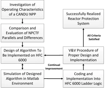
1.4.3 Solution Technique
To achieve these objectives, a number of steps must be taken. These steps are outlined
in Figure 1.2. The work shall begin with a literature review of the relevant CANDU
technologies and research. Following is a description of the NPCTF system. Once the system
is described, the safety control algorithm design may begin. A Matlab simulation shall be
created and continual improvements made on the design. Once simulation results are
satisfactory, the implementation on HFC6000 may begin. The V&V process follows. This
includes opportunities for improvement by retuning the algorithm. When all criteria have been
achieved, the system will be fully realized.
Investigation of Operating Characteristics
of a CANDU NPP
Comparison and Evaluation of NPCTF Parallels and Differences
Design of Algorithm To Be Implemented on HFC
6000
Simulation of Designed Algorithm in Matlab
Environment
Coding and Implementation Into HFC 6000 Ladder Logic
V&V Procedure of Proper Design and Implementation Successfully Realized Reactor Protection System Continual Improvement All Criteria Satisfied
1.5
Contributions of the Thesis
This thesis has made three major contributions:
1. The investigation of the NPCTF critical parameters is completed such that the
relationships and dependence on the heater current are fully characterized
2. The cross comparison between NPCTF and CANDU operating signals and
dynamics is performed to a degree capable of permitting the design of a RPS
3. An RPS is designed to operate on the NPCTF capable of achieving specified
performance criteria: a perfect record in fault detection and no spurious trips
during validation testing
1.6
Performance Criteria
The RPS must be capable of meeting design criteria. Thus, it is necessary that these
criteria are specified such that they may be tested against. Though speed of the system is a
performance measure of a RPS, this cannot be plausibly measured using the operations of the
NPCTF. The RPS performs at rates too quick for the recording devices in question. However,
given that the recording instruments operate at 1Hz, the performance criteria are therefore:
1. The system must be capable of detecting all faults inserted without exception.
Specifically, these faults will be those outlined in CNSC regulatory document R-8
2. The system must not be the cause of spurious trips. The NPCTF, as the system under
test, must be able to perform all permissible operations without interference from the
RPS
3. All trips must occur within 1s. This will be measured by the NPCTF’s internal log and
defined as occurring from the recorded bypass to the recorded moment of complete
1.7
Organization of the Thesis
The thesis consists of six chapters including this Introduction. The second Chapter
presents a literature review and essential background about CANDU reactors, nuclear safety,
V&V methods, techniques for safety system design, and information about PLC including the
HFC6000. The subsequent chapter contains an in-depth investigation of the NPCTF physical
characteristics and operation. Chapter 4 is a detailed explanation of the safety system,
including the method of designing set points, the functions of the software, and techniques
used to verify its operation. Chapter 5 details the V&V process used: the reasoning behind the
tests and the means to perform these tests. Here, the results of experiment trials are presented,
2
Literature Review
2.1
CANDU Reactor
2.1.1 Heavy Water Moderator
Certain design features of the CANDU reactor affect the design of relevant safety
systems. The first is the CANDU choice of moderator: D2O (AKA heavy water). Moderators
are used to slow, through repeated collisions or ‘scattering’, the neutrons released from fission.
This is done so that the neutrons are absorbed into other fissile atoms rather than passing
through them at near-light speeds [32]. Heavy water possesses a large scattering cross-section,
a small absorption cross-section, and large energy losses per collision [32]. Amongst
moderators, heavy water possesses the best performance for the first two criteria and is
surpassed by only light water in the third.
The average log energy decrement describes energy lost per collision. It is defined as
[32]:
𝜉 = ln𝐸𝑖𝑛𝑐𝑜𝑚𝑖𝑛𝑔 𝐸𝑠𝑐𝑎𝑡𝑡𝑒𝑟𝑒𝑑
(1)
where is the average log energy decrement, and Eincoming and Escattered are the energy levels of
the neutron before and after collision. This value is almost entirely empirical as its value must
be investigated through experimentation. However, a very rough estimation can be made as
[32]:
𝜉 = 1 −(𝐴 − 1)2 2𝐴 ln
(𝐴 + 1) (𝐴 − 1)
where A is the atomic mass. Using either observed or estimated values, it becomes possible to
estimate the total number of particle collisions necessary to slow neutrons to appropriate
velocities. Assuming each loss is near the average log energy decrement, the total number of
collisions could therefore be calculated as [32]:
𝑁 =ln 𝐸ℎ𝑖𝑔ℎ
𝐸𝑙𝑜𝑤 𝜉
⁄ (3)
where N is the expected number of collisions, and Ehigh and Elow are the starting and required
energy levels. Ultimately, the fewer collisions needed to bring neutrons to appropriate
velocities, the more easily the reaction will propagate.
The two other important factors are the scattering-cross-section and the
absorption-cross-section [32]. A good moderator will have a much larger scattering than absorption cross
section, such that neutrons are slowed down but not removed from the ongoing reaction.
Combining all three crucial characteristics is the moderating ratio, MR [32]:
𝑀𝑅 = 𝜉𝜎𝑠 𝜎𝑎
(4)
where s is the scattering cross section and a is the absorption cross section. Observing the
Table 2.1: Effectiveness of Common Moderators.
Material Ave. Log Energy Decrement
Necessary Collisions
Macro Slowing Power
Moderating Ratio
H2O 0.927 19 1.425 62
D2O 0.510 35 0.177 4830
He 0.427 42 9e-6 51
Be 0.207 86 0.154 126
B 0.171 105 0.092 0.00086
C 0.158 114 0.083 216
As mentioned in Section 1.1, CANDU NPPs use natural uranium as their fuel source.
Natural uranium, being significantly more inert than the enriched uranium of light water
reactors, forces improved moderator performance to maintain the ongoing reaction.
CANDU NPPs thus submerge and contain the reactor core in a vessel known as the
calandria, as shown in Figure 1.1, and again in Figure 2.2. The calandria and primary loop are
each filled with heavy water to act as the moderator and the coolant respectively. This
maximizes the likelihood a released neutron will be slowed and return to the reaction. Heavy
water thus allows CANDU NPPs to sustain a chain reaction without the need for enriched
uranium.
2.1.2 Neutron Economy
The proportional growth and decay of the number of free neutrons is referred to as the
‘neutron economy’. Maintenance of the neutron economy is critical as the power of the reactor
Explicitly, this is expressed as [33]:
𝑃 = 𝐸𝑅𝑁𝑑𝜎𝑓𝜙𝑉 (5)
where P is the reactor power, ER is energy released per fission (~200MeV), Nd is the fissile
density number (~1024/cm3), σf is the cross-section of the atoms, Φ is the instantaneous neutron
flux, and V is the reactor volume [33].
Released neutrons are divided into two categories based on their rate of release from
their atom [33]. The first category, ‘prompt’ neutrons, come from atoms that decompose
within 10-17s after absorption of a neutron. ‘Delayed’ neutrons are those released from atoms
that decompose more slowly. Delayed neutrons are often released in six distinct steps resulting
from the incremental decay of U235 into Sr87 [33]. From the initial absorption, these delayed
neutrons are released anywhere from 0.23s up to 55.72s. U235, the fissile isotope used in
CANDU, has a total delayed neutron fraction of 0.0065, or 0.65% [33].
This disparity demonstrates the importance of understanding the neutron economy
when designing a reactor protection scheme. With most propagations taking less than 10-17s,
neutron economy can quickly advance to dangerous levels. Additionally, with some releases
requiring nearly a minute, and many of the created radioactive by-products requiring much
longer, reactors continue to produce heat long after being shut down.
Effective multiplication factor, keff, represents the ratio between the population of the
current generation of free neutrons and the population of the next [33]. It thus follows that
when keff is greater than one: the economy is growing, and when less than one: the economy is
shrinking. The targeted value is one, referred to as ‘unity’, such that the reactor remains at
From keff the excess multiplication factor is defined as [33]:
𝑘𝑒𝑥= 𝑘𝑒𝑓𝑓− 1 (6)
where kex is the excess multiplication factor. From here, the ‘reactivity’, ρ, is defined as the
ratio between the excess multiplication factor and the effective multiplication factor [33]:
𝜌 = 𝑘𝑒𝑥 𝑘𝑒𝑓𝑓
(7)
such that increasing reactivity corresponds to positive values, and decreasing reactivity
corresponds to negative values.
The most important factors effecting the reactivity are: fuel temperature, coolant
temperature, coolant void, moderator temperature, reactor power, moderator poisons, and
fission products [2]. However, long term considerations include depletion of fuel, active
breeding, and accumulation of fission by-products (called reactor poisons) [33].
In a CANDU reactor, the reactivity in the core has to be under control at all times.
Light water channels in the reactor may be filled to decrease reactivity, and boric acid in the
moderator or cadmium control rods removed to increase reactivity [34]. These mechanisms
are controlled by the reactor control system, ensuring that the reaction remains stable. When
circumstance leads to the failure of these mechanisms, either due to their own loss of control
or the presence of faults, it becomes the role of the RPS to intervene.
These details of reactor physics are presented to demonstrate the importance of the
ongoing decaying heat of delayed decompositions require sufficiently thorough and long
lasting responses, and careful examination during start-up procedures.
Second, the exponential characteristic of the neutron economy necessitates rapid
response as reactions may quickly ‘run-away’. As a prompt neutron is released 10-17s after
initial absorption, generations of neutrons are released and absorbed rapidly. A positive value
of ρ that persists for even short periods of time greatly effects the system, as reactor power, P,
is directly proportional to the instaneous flux, Φ. This necessitates rapid action on behalf of
the RPS, as the exponential growth ultimately implicates sudden and immense increases of
reactor core temperature.
2.2
Reactor Protection Systems: Overview
All nuclear reactors possess the capability to release radiation, rupture to release
superheated steam, and/or meltdown. While a reactor cannot explode in the manner of a
nuclear warhead [35], the inherent risks of nuclear power generation demand that the RPS
remain poised to place the reactor into a safe state at any moment. The two systems to perform
this task are shutdown system 1 and 2, referred to as SDS1 and SDS2. These are controlled by
monitoring safety systems. Safety systems are not involved in the control of the NPP. Instead,
they monitor the critical parameters of the NPP, alert operators to dangerous conditions, and
determine when an intervention is necessary. The logical configuration of an NPP is shown in
`
Operation Console
Nuclear Power Plant
Reactor Protection System Channel 3 Shutdown Systems Process Controller Process Controller Process Controller Process Controller Process Controller Reactor Protection System Channel 2 Voting Reactor Protection System Channel 1 Field Instruments Distributed Control System Instrumentation and Control Devices Instrumentation and Control Devices Instrumentation and Control Devices Instrumentation and Control Devices Instrumentation and Control Devices Safety Systems
Figure 2.1: Safety Systems and Control Systems of a Nuclear Power Plant
2.2.1 Shutdown Systems 1 and 2
Each SDS is required by law to be independently capable of halting the nuclear reaction
[36]. Also, their operation must not interfere with the capability of the other. The systems
must individually achieve an unavailability 1/1000th of a year annually. As such, their
combined unavailability is one in a million, or 10-6 [22]. This allots just 8 hours annually per
system, including maintenance, full system testing, or any off-line operations.
SDS1 is a group of 32 shutdown rods capable of immediately stopping the nuclear
reaction through the absorption of neutrons [37]. Without these neutrons, the nuclear reaction
fails to propagate and the reactor ceases to produce as much heat. These rods are a cadmium
alloy, coated in stainless steel for strength [37]. When the cadmium atom absorbs a neutron it
produces only a photon in response [38]. This photon may be absorbed but the reaction has
The cadmium rods are positioned above the reactor core, held by electromagnetic
clutches or magnetically coiled springs [37]. This can be seen in Figure 2.2. Gravity and/or
spring power rapidly forces the rods into the reactor core when released. All 32 rods are
inserted within 2 seconds [38] and possess enough negative reactivity that even the two most
effective rods may fail to insert with no consequence [33].
SDS2 is a liquid neutron absorber [37]. This is typically referred to as ‘reactor poison’
[37]. The reactor poison is considerably more destructive than the shutdown rods and its
effects on the reactor core can only be undone through special means. The reactor poison is a
gadolinium nitrate (GdNO3) mixture which, like cadmium, acts as a neutron absorber [37].
The gadolinium nitrate is kept in tanks adjacent to the reactor [37] as shown in Figure
2.2. These are kept pressurized through the helium tanks shown directly above the GdNO3
tanks. When necessary, SDS2 releases the normally open valves at the bottoms of the poison
tanks. Under the pressure provided by the helium tank, reactor poison is injected into the
moderator [37]. Theses valves are high reliability [22] and designed to be normally open (that
is, spilling into the moderator) [37]. The safety system is thus actively keeping the poison out
of the reactor. This is another fail-safe design such that the failure of the safety or shutdown
Figure 2.2: CANDU Shutdown Systems
The gadolinium rods of SDS1 are capable of being withdrawn from the reactor core via
chains, while SDS2 must be laboriously cleaned from the moderator [37]. Because of this, the
two systems are staggered in actuation. It is preferable SDS1 handles the shutdown
individually as recovery is faster and less expensive. Thus, SDS1 typically posesses more
conservative set points so it remains first to actuate [37]. Though both systems are available,
2.2.2 Safety Systems
Safety systems are responsible for initializing the shutdown of the reactor (known as a
‘trip’) through the SDS [39]. CANDU utilizes at least three safety systems to control the two
SDS. The safety systems initialize trips collectively by utilizing two-out-of-three (or 2oo3)
voting logic, allowing each safety system to be prudently cautious without risking spurious
trip.
The safety systems make judgements through monitoring of trip parameters [39].
Safety systems initialize trips when parameters reach their respective trip thresholds.
Determining trip thresholds is discussed in section 2.4.
Safety systems have gone through four major generations [40]. The first generation
utilized relay logic and operator interfaces consisting of mounted meters and lights in the
control room. Operations were recorded with multipen trend recorders and operators
controlled the plant through pushbuttons and hand switches.
The next generation began with the introduction of monitoring computers [40]. These
computers did not change the NPP’s circuitry or much of the interface, but allowed data
manipulations, statistical checks, and comparisons to be generated. This information could be
displayed to the operators [40]. The computers increased the capability to record plant
operations and could more easily track trends. Subsequently, early warning logic was
implemented to warn of impending trip conditions.
Programmable digital comparators (PDCs) were the first to replace analog devices [39].
Instrumentation remained analog and interfacing tools remained unchanged, but signal
conservative: neutronic trips did not migrate to digital for safety concerns [40]. However,
PDC’s made digital logic evaluation and process trips possible.
Now, fully computerized shutdown systems are possible. Instrumentation remains
analog though monitoring, testing, logic, and display are fully digital [40]. CANDU safety
systems utilize 15 computers between the two SDS, each with specialized tasks including
monitoring parameters, tripping, display/testing, and monitoring the other computers [40].
Modern safety systems attempt to minimize unnecessary reliance on software. Failure
of any aspect of the software must be fully understood with reliability measures (ex. error
checking) included. Darlington, as an example, utilizes over two-thirds of its safety system’s
code to error check the implemented logic [39].
2.3
Design Methods of Reactor Protection Systems
A safety system is defined as the system responsible for autonomously initiating
shutdown in an NPP [32]. Conversely, the SDS is the body of mechanisms that are responsible
for carrying through with that task [40]. Thus, it is the safety system which holds the logic,
processes the system parameters, and discerns if and when a trip is necessary.
The importance of this task begets a number of common design criteria. Other than the
vigorous testing that must be performed during V&V, engineering principles are utilized to
mitigate issues that arise due to environment and failures of foresight [41].
2.3.1 Key Monitoring Parameters
Safety systems typically refer to the choice of monitored system variables as the safety
are likewise refered to as safety paratmers. CANDU safety algorithms often examine a similar
set of parameters. These parameters are chosen due to their proven capability of detecting
faults or abnormalities in the CANDU design [37]. Common parameters for SDS1 are listed in
Table 2.2 along with which conditions abnormalities in those parameters could indicate [37].
Table 2.2: Common CANDU Safety Parameters.
Tripping Signal Common Cause
Neutron Flux Level – High Reactor power level too high
Neutron Rate Log Power change too quick, unstable reactor Steam Generator Level – Low Loss of heat sink
Feed water Line Pressure – Low Loss of heat sink Pressurizer Level – Low Loss of coolant
Primary Line Pressure – High Reactor power too high for eat sink Primary Line Pressure – Low Poor coolant flow
Primary Line Flow – Low Poor coolant flow Reactor Building Pressure – High Containment break Moderator Level – Low Reactor instability
Moderator Temperature – High Cooling issue. Reactor power level too high Manual Trip Discretion of operating crew
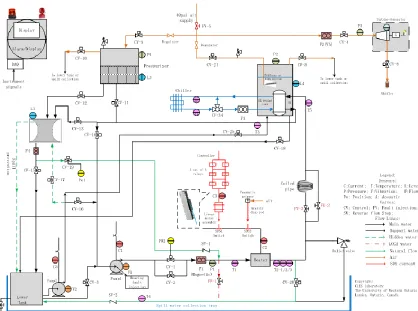
When designing the NPCTF’s safety algorithm, these parameters were mirrored in
order to retain the CANDU parallel. Referencing Figure 3.1 in section 3.1, the equivalents in
the NPCTF for the parameters in Table 2.2 are shown in Table 2.3.
Table 2.3: NPCTF Equivalent Signals.
CANDU Critical Signal NPCTF Equivalent
High Neutron Power None High Rate of Rise of Neutron Power None
High Coolant Pressure Primary Loop Pressure (P1) Low Coolant Pressure Primary Loop Pressure (P1) High Building Pressure None
Low Steam Generator Level HX Tank Level (L4) Low Pressurizer Level Pressurizer Level (L3)
Because the nuclear reactor is simulated by a heater on the NPCTF, a number of
CANDU parameters relating to neutron flux and the reactor building possess no NPCTF
equivalent. However, the NPCTF still possesses equivalents for 8 of the 11 shutdown signals.
This will be discussed in greater detail in section 3.1.
Because the redundant safety systems must still be diverse; safety systems monitor
different sets of parameters, though there exists some overlap between them. An example set
of parameters commonly used for SDS2 are listed in Table 2.4, along with failures they could
indicate [37].
Table 2.4: Common CANDU Safety Parameters.
Signal Common Cause
Neutron Power – High Reactor power level too high
Neutron Rate Log – High Power change too quick, unstable reactor Primary Line Pressure – High Loss of flow, heat sink failure
Primary Line Pressure – Low Leak in primary Reactor Building Pressure – High Steam line break
Steam Generator Level – Low Steam/feed water line breaks Pressurizer Level – Low Leak in primary line
Pressure Differential in Primary – Low Flow blockage/failure Steam Generator Pressure – Low Steam line break
These signals are equally valid in designing the safety algorithms to protect the plant.
However, because it is preferable to initiate the destructive SDS2 after SDS1, the set points for
initiating a trip through SDS2 are slightly less stringent [37]. Regardless, the redundancy
introduced by diverse the SDS and their respective logic increases overall system reliability.
2.3.2 Redundancy
A common CANDU safety design is two-out-of-three (2oo3) triplicated logic. This
requires two of the three safety functions to call for a trip before one can occur [42]. This
methodology possesses a number of operating benefits [42]:
Allows a single system to be tested while the other two systems remain redundant and
in operation
Should a system fail it automatically votes to ‘trip’; neither compromising safety nor
resulting in a spurious trip
Allows operators to view read-outs from each safety system, clearly showing when one
system possesses an anomalous reading
Permits the tightest possible parameter bounds without excessive risk of initiating
spurious trip
Triplication is not applied only to safety systems. Many sensors and other
instrumentation devices make use of triplicated redundancies in order to minimize errors [35].
These redundancies may even take place at the circuit level, where primary and secondary
calculations are performed on separate processors [43]. If the calculations by two processors
do not match, chip error protocol is utilized. If the error continues, the device recognizes a
malfunction and performs predetermined actions [43].
Darlington’s redundant safety systems are fully computerized [39]. Darlington’s safety
system possesses three groups of computers, each monitored separately by independent
watchdog devices [9]. The redundancy of three groups prevents errors while the independent
12,000 words that make up the trip software, over 8,000 (2/3 of the total) are used purely for
self and cross checking the results of any calculation [39].
2.3.3 Diversity of Design
Common cause failures (CCFs) are antagonistic to redundancies [17]. CCFs are events
that result in failures across several systems [17]. Because CCFs by definition affect multiple
systems, they render redundancy frivolous [17]. A simple example is a power surge that results
in a measurement error by each system. CCFs are a principle concern to safety design because
they represent a possibility that all safety systems could fail from a single, unexpected source
[17].
Because CCFs cannot be predicted, the best protective measure is diversity of design
[17]. Diversity is systematically approached so that redundant or complementary systems have
as little in common with one another as is practically possible [17]. Theoretically, diverse
systems accomplishing their tasks with differing tools, methodologies, and equipment may
cause more total failures, but these failures will be from different causes and happen at different
times [17].
Diversity is a standardized IAEA concept. Many safety standards include diversity as
a necessary aspect of safety critical systems [19], [44]. In particular, the IEC 60880, 62340,
61508-2 (parts 2, 3, and 7) as well as the IAEA NS-G-1.1 and 1.3 form part of the international
community’s criteria on diversity in NPPs [45], [46].
The aforementioned standards possess requirements in the application of diversity as
well as minimum standards in quantized measures of the principle. Some, but not all of these
redundancy that apply, and recommendations on assessment [45], [46]. Detailed techniques
in the evaluation of the systems is discussed in NUREG-7007, a referenced but
non-standardized approach to diversity evaluation [47].
In general, diversity is realized from seven applicable vantages [47]:
1) Design: Methodology in approaching a task or problem
2) Equipment Manufacturer: To insure another company’s CCFs don’t enter the NPP
3) Logic Processing Equipment: To account for the inherent weaknesses of all types
4) Function: The means by which tasks are carried out
5) Life-Cycle: Stresses or environmental factors common between systems
6) Signal: In line, instrument, and when applicable: the signals themselves
7) Logic: The implemented software and machine reasoning, be it µP based, ladder, or
otherwise
Evaluation of diversity in redundant systems has several options. The most used
methodology is NUREG-A as found within the NUREG-7007 [47]. Other methods include
check-list based, RBD (or MM) based, graph-model based, and those which derive from
probabilistic metrics [49].
An important concept in these methods is the difference between inherent and intentional
diversity [49]. Intentional diversity is using the same technology or methodology in a different
way for the explicit introduction of diversity. Contrarily, inherent diversity is completely
When choosing between separate options, the IAEA insists the selection of the most diverse
designs [48]. However, the IAEA recognizes that other factors (such as complexity, cost, and
maintenance) may be considered.
2.4
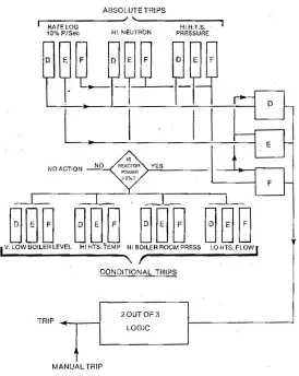
CANDU Shutdown Logic
As discussed, the CANDU shutdown logic is divided between conditional and absolute
trips. Conditional trips are armed when reactor power is at greater than 2% of maximum [37].
At low reactor power, the conditional trip parameters are not critical to safety. Absolute trips
remain armed at all times. The general logical structure of CANDU shutdown logic is shown
in Figure 2.3 [37].
Presented in Figure 2.3 are 7 of the shutdown thresholds. Each SDS utilizes three
separate and independent channels (marked D, E, and F for SDS1, and G, H, and I for SDS2).
The triplicated measurements work with 2oo3 logic, requiring two channels to exceed setpoints
before a trip is initiated and reducing the possibility of spurious trip. These channels are
exclusive to the safety systems [37].
Trip thresholds are separated for SDS1 and SDS2, with SDS2 designed to operat at
higher setpoints [37]. However, these thresholds are designed in ‘fail-safe’ such that they are
actively preventing the SDS from acting. Upon loss of signal from the safety systems, the SDS
will activate to halt the reaction [37].
2.5
Trip Set-point Determination
The safety system, using the critical operating parameters, monitors the system for if
and when breaches of predefined thresholds occur [1]. These thresholds are chosen such that
even in worst case scenarios the SDS remain capable of reversing the supercriticality of the
reactor core. An improperly placed threshold may result in system damage, release of
radiation, or worse [50].
Threshold determination fundamentally begins from the understanding that an NPP
may produce undesired effects [51]. All of these effects may be grouped together under the
term ‘damage’. The point at which a system parameter results in damage is referred to as the
‘safety limit’. Thus, safety limits should never be met or breached in order to prevent the
occurrence of damage [51].
As shown in Figure 2.4 [52], a safety margin is the breadth given to a safety limit even
through a very high value), the safety margin is maintained by an ‘acceptance criterion’ at its
base [52]. The acceptance criterion is the designed maximum value of the parameter. The
RPS is therefore designed to prevent the parameter from ever breaching the acceptance
criterion. If a parameter is halted before reaching its acceptance criterion, the safety margin is
said to be ‘preserved’ [52].
Figure 2.4: Definition of Margins in a Nuclear Power Plant.
Preservation of the safety margin requires the reactor to shut down well before the
acceptance criteria is met. The parameter value at which action is taken is referred to as either
the tripping set point or the tripping threshold. The tripping set point (labelled as the ‘operating
envelope limit’), the safety limit, and acceptance criterion additionally utilize significant
uncertainties are shown in Figure 2.4. Uncertainties originate from many sources, as discussed
The decision behind the tripping threshold is mostly determined through the simulation
of a worst-case-scenario. This scenario is a ‘design basis event’ [53]. Several design basis
events must be utilized in each safety system design. The most infamous of these is the large
loss-of-coolant-accident (LOCA).
The design basis LOCA is a complete shearing of the coolant inlet pipe immediately
before the reactor. This results in coolant being rapidly drained from the calandria, a massive
pressure loss, and consequent overheating of the reactor [53]. The large LOCA as a design
basis event requires the swiftest response, theoretically resulting in the most conservative
tripping set points [53].
Using the design basis event, engineers rely on modelling and simulation to evaluate
the tripping set point. These are heavy calculations that rely on high accuracy modelling and
thorough understanding of uncertainties. Uncertainty plays such a large role in the calculation
of tripping set points that the IAEA publishes recommendations on uncertainty investigations.
Historically, uncertainty is treated as pessimistically as possible in order to maximize safety
[52].
2.5.1 Uncertainty Measurements and Calculations
Tripping set point determination continue to be an area of improvement and research
in nuclear design. New methodologies have been proposed, tending to focus on the
improvement of modelling and computations [54-56].
The unique aspects of new methodologies tend to be the means by which uncertainties
are handled in simulation. Design basis events of simultaneous multiple failures, compounded