Javid
4, Arslan Ahmad
51
Assistant Professor, Dept of EEE, Lords Institute of Engg.& Tech.,JNTUH,
Hyderabad,Telangana, India
2
Student, Dept of EEE, Lords Institute of Engg.& Tech., JNTUH, Hyderabad, Telangana, India
3Student, Dept of EEE, Lords Institute of Engg.& Tech., JNTUH,
Hyderabad, Telangana, India
4Student, Dept of EEE, Lords Institute of Engg.& Tech., JNTUH,
Hyderabad, Telangana, India
5Student, Dept of EEE, Lords Institute of Engg.& Tech.,
JNTUH,
Hyderabad, Telangana, India
Abstract: This paper proposes a single-phase to three-phase drive system composed of two parallel single-phase rectifiers, a three-phase inverter, and an induction motor. The proposed topology permits to reduce the rectifier switch currents, the harmonic distortion at the input converter side, and presents improvements on the fault tolerance characteristics. Even with the increase in the number of switches, the total energy loss of the proposed system may be lower than that of a conventional one. The model of the system is derived, and it is shown that the reduction of circulating current is an important objective in the system design. A suitable control strategy, including the pulse width modulation technique (PWM), is developed. Experimental results are presented as well.
Index Terms: - Ac-dc-ac power converter, drive system, parallel Converter, Fault Identification System (FIS).
I. INTRODUCTION
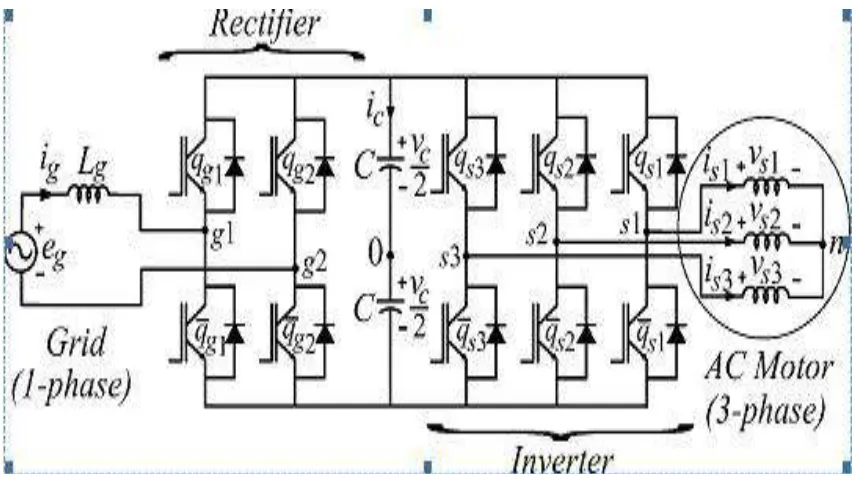
Several solutions have been proposed when the objective is to supply a three-phase motor from single-phase ac mains [1]-[4]. It is quite common to have only a single phase power grid in residential, commercial, manufacturing, and mainly in rural areas, while the adjustable speed drives may request a three-phase power grid. Single-three-phase to three-three-phase ac–dc– ac conversion usually employs a full-bridge topology, which implies in ten power switches. This converter is denoted here as conventional topology. Parallel converters have been used to improve the power capability, reliability, efficiency, and redundancy. Parallel converter techniques can be employed to improve the performance of active power filters [5]-[6], uninterruptible power supplies (UPS) [7], fault tolerance of doubly fed induction generators, and three-phase drives [8]. Usually the operation of converters in parallel requires a transformer for isolation. However, weight, size, and cost associated with the transformer may make such a solution undesirable [9]. When an isolation transformer is not used, the reduction of circulating currents among different converter stages is an important objective in
the system design [10]-[12]. In this paper, a single-phase to three-single-phase drive system composed of two parallel single-phase rectifiers and a three-phase inverter is proposed. The proposed system is conceived to operate where the single-phase utility grid is the unique option available. Compared to the conventional topology, the proposed system permits: to reduce the rectifier switch currents; the total harmonic distortion (THD) of the grid current with same switching frequency or the switching frequency with same THD of the grid current; and to increase the fault tolerance characteristics. In addition, the losses of the proposed system may be lower than that of the conventional counterpart. The aforementioned benefits justify the initial investment of the proposed system, due to the increase of number of switches.
II. METHODS TO CONNECT SINGLE PHASE TO THREE PHASE DRIVE SYSTEMS 2.1 Static Phase Converter:
the motor to continue to run on just 1 phase and only part of its windings. Due to their technology, Static Phase Converters do not properly power any class of 3 phase machinery or equipment. They will not in any way power 3 phase welders, 3 phase battery chargers, 3 phase lasers, or any type of machinery with 3 phase circuitry. Static Phase Converters also will not start delta wound 3 phase motors.
2.2 Rotary phase converter:
A rotary phase converter, abbreviated RPC, is an electrical machine that produces three-phase electric power from single-phase electric power. This allows three phase loads to run using generator or utility-supplied single-phase electric power. A rotary phase converter may be built as a motor-generator set. These have the advantage that in isolating the generated three-phase power from the single phase supply and balancing the three-phase output. However, due to weight, cost, and efficiency concerns, most RPCs are not built this way. Rotary Phase Converters Provide Reliable, Balanced, and Efficient Three Phase Power. Quick and Effective Three Phase Electricity.
All converters can be mainly categorized into two groups: one is cascade type and another is unified type [2]. In cascade type, the PWM converter for power factor correction and the PWM inverter for speed control are connected in series with large DC-Link capacitor and two static power converters are operated and controlled in separate. In this type, specific number of switches, to compose the converter and inverter, are required. Therefore, the required number of switches cannot be reduced significantly. On the other hand, in the unified type, conventional concepts of PWM converter and inverter are merged together and same converter handles the functions of PWM converter (power factor correction) and PWM inverter(motor control) at the same time. As an added advantage, the input inductor, which is commonly used in the PWM converter for power factor correction, can be eliminated and replaced by the existing motor inductor. Therefore, this new concept can significantly reduce the number of components, compared to any conventional cascade type topologies.
III. SYSTEM MODEL
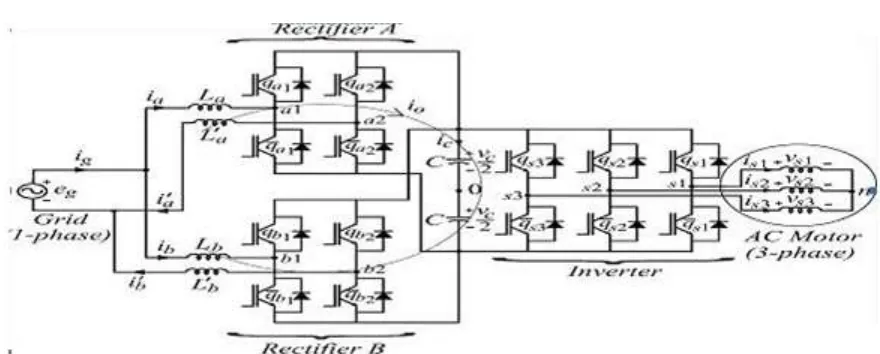
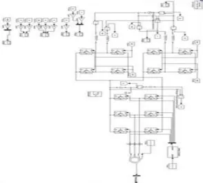
Fig 2 Proposed single-phase to three-phase drive system The system is composed of grid, input inductors ( ,′ , , ′ ).Rectifiers (A and B), capacitor bank at the dc-link, inverter, and induction machine. Rectifiers A and B are constituted of switches and and and respectively. The inverter is constituted of switchesand . From Fig. 2, the
following equations can be derived for the front-end rectifier
Where
p
=
d/dt
and symbols like
r
and
l
represent the resistances and inductances of the input inductors
The circulating current can be defined from
IV. PWM STRATERGY
The PWM strategy for the rectifier will be presented. The rectifier pole voltages and depend on the conduction states of the power switches, i.e.,
V. CONTROL STRATERGY
The control block diagram of Fig 2 highlighting the control of the rectifier to control the dc-link voltage and to guarantee the grid power factor close to one. Additionally, the circulating current in the rectifier of the proposed system needs to be controlled is shown below:
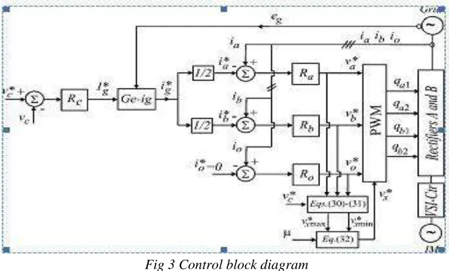
Fig 3 Control block diagram
In this way, the dc-link voltage is adjusted to its reference value using the controller Which is standard Fuzzy logic controllers. This controller provides the amplitude of the referencegrid current To control power factor and harmonics in the grid side, the instantaneous reference current must be synchronized with voltage , as given in the voltage-oriented control (VOC) for three-phase system This is obtained via blocks Ge-, based on a PLL scheme. The reference currents and are obtained by making ==.Which means that each rectifier receives half of the grid current. The control of the rectifier currents is implemented using the controllers indicated by blocks and . These controllers can be implemented using linear or nonlinear techniques. The homopolar current is measured () and compared to itsreference (= 0). The error is the input of Fuzzy controller ,that determines the voltage . The calculation of voltage isgiven from (30) to (32) as a function of μ, selected.The motor there phase voltages are suppliedfrom the inverter (VSI). Block VSI-Ctr indicates the inverterand its control. The control system is composed of the PWMcommand and a torque/flux control strategy.
VI. FAULT COMPENSATION
SCRs—t1 , t2 , t3 ), as observed in Fig. 10(a)and discussed. These devices are used to redefine the post-fault converter topology, which allows continuous operation of the drive after isolation of the faulty power switches in the converter. Fig. 7.8.1(b) presents the block diagram of the fault diagnosis system. In this figure, the block fault identification system (FIS) detects and locates the faulty switches, defining the leg to be isolated. This control system is based on the analysis of the pole voltage error. The fault detection and identification is carried out in four steps:
1. Measurement of pole voltages ().
2. Computation of the voltage error by comparison of reference voltages and measurements affected in Step (1).
3. Determination as to whether these errors correspond or not to a faulty condition; this can be implemented by the hysteresis detector.
4. Identification of the faulty switches by using.
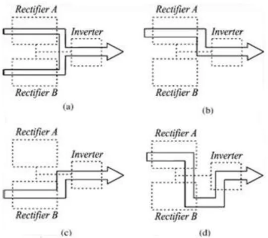
Fig.5 Possibilities of configurations in terms of fault occurrence. (a) Prefault system. (b) Post-fault system with fault at the rectifier B. (c) Post-fault system with fault at the rectifier A. (d) Post-fault system with fault at the inverter. This way, four possibilities of configurations have been considered in terms of faults:
1) pre-fault (―healthy‖) operation
2) post-fault operation with fault at the rectifierB 3) post-fault operation with fault at the rectifierA 4) post-fault operation with fault at the inverter
Table 1 Efficiency of the proposed system normalized in terms conventional one
When the fault occurrence is detected and identified by the control system, the proposed system is reconfigured and becomes similar to that in Fig.1.For instance, if a fault in any switch of rectifier A has been detected by the control system, the hole rectifier needs to be isolated. This isolation procedure depends on the kind of fault detected. If an open-circuit failure is detected, the control system will open all switches of the rectifier A. On the other hand ,if a short circuit is detected, the control system will turn on all switches related to rectifier A, and in this case, the fuses will open, and consequently, the rectifier will be isolated, as discussed. Considering now a fault in one leg of inverter, in this case the SCR related with this leg in turned on and the leg b1 is isolated, so that the leg b2 of rectifier B will operate as the leg of inverter.
VII. MATLAB SIMULINK MODELS
Fig 9 Fault Identification at Rectifier B VIII. RESULTS
(a)
(c)
(d)
(e)
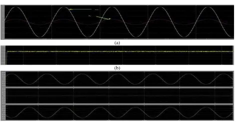
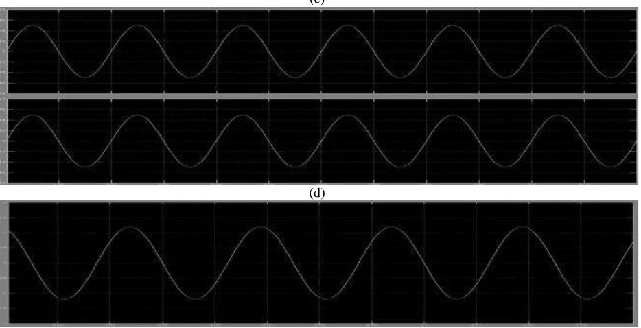
Fig. 10 Shows the waveforms of steady state three phase motor: (a) voltage and current of the grid, (b) dc-link voltage, (c) currents of rectifier A and circulating current, (d) currents of rectifiers A and B, and (e) load
line voltage.
(a)
(c)
(d)
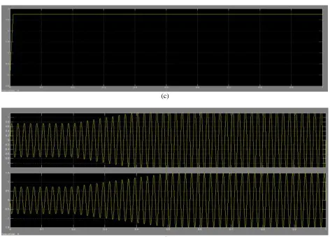
Fig 11 Experimental results when fault occurs at rectifier B. (a) Grid voltage and grid current (b) Currents of rectifiers A and B (c) Capacitor voltage (d) Currents of rectifier A
IX. CONCLUSION
A single phase to three phase drive system using two parallel converters, three phase inverter and induction motor are proposed. The comparison between conventional and proposed system has been carried out and experimental results are also shown.
REFERENCES
[1] P. Enjeti and A. Rahman, ―A new single
phase to three phase converter with active input
current shaping for low cost AC motor drives,‖
IEEETrans. Ind. Appl., vol. 29, no. 2, pp. 806–
813, Jul./Aug. 1993.
[2] B.K. Lee, B. Fahimi, and M. Ehsani,
―Overviewof
reduced
parts
converter
topologies for AC motor drives,‖ in Proc. IEEE
PESC, 2001, pp. 2019–2024.
[3] C. B. Jacobina, M. B. de R. Correa,A.M. N.
Lima, and E. R. C. da Silva, ―AC motor drive
systems with a reduced switch count converter,‖
IEEETrans. Ind. Appl., vol. 39, no. 5, pp. 1333–
1342, Sep./Oct. 2003.
[4] C. B. Jacobina, E. C. dos Santos Jr., E. R. C.
da Silva, M. B. R. Correa,A. M. N. Lima, and T.
M. Oliveira, ―Reduced switch count multiple
three-phaseac machine drive systems,‖ IEEE
Trans. Power Electron., vol. 23,no. 2, pp. 966–
976, Mar. 2008.
[6] L. Woo-Cheol, L. Taeck-Kie, and H.
Dong-Seok, ―A three-phase parallel active power
filter operating with PCC voltage compensation
with consideration for an unbalanced load,‖
IEEE Trans. Power Electron., vol. 17, no. 5, pp.
807–814, Sep. 2002.
[7] L. Asiminoaei, E. Aeloiza, P. N. Enjeti, F.
Blaabjerg, and G. Danfoss, ―Shunt
active-power-filter
topology
based
on
parallel
interleaved inverters,‖ IEEE Trans. Ind.
Electron., vol. 55, no. 3, pp. 1175–1189, Mar.
2008.
[8] M. Ashari, W. L. Keerthipala, and C. V.
Nayar, ―A single phase parallel connected
uninterruptible
power
supply/demand
side
management system,‖ IEEE Trans. Energy
Convers., vol. 15, no. 1, pp. 97–102, Mar. 2000.
[9] J.-K. Park, J.-M. Kwon, E.-H. Kim, and
B.-H. Kwon, ―High-performance transformer less
online UPS,‖ IEEE Trans. Ind. Electron., vol. 55,
no. 8, pp. 2943–2953, Aug. 2008.
[10] Z. Ye, D. Boroyevich, J.-Y. Choi, and F. C.
Lee, ―Control of circulating current in two
parallel three-phase boost rectifiers,‖ IEEE
Trans. PowerElectron., vol. 17, no. 5, pp. 609–
615, Sep. 2002.
[11] S. K. Mazumder, ―Continuous and
discrete variable-structure controls for parallel
three-phase boost rectifier,‖ IEEE Trans. Ind.
Electron., vol. 52, no. 2, pp. 340–354, Apr.
2005.
[12] Z. Ye, P. Jain, and P. Sen, ―Circulating
current minimization in high frequency AC
power distribution architecture with multiple
inverter modules operated in parallel,‖ IEEE
Trans. Ind. Electron., vol. 54, no. 5,. pp. 2673–
2687, Oct. 2007.
[13] J. Holtz, ―Pulse width modulation for
electronic power conversion,‖ Proc.IEEE, vol.
82, no. 8, pp. 1194–1214, Aug. 1994.
[14] M. P. Kazmierkowski and L. Malesani,
―Current control techniques for three-phase
voltage-source PWM converters: A survey,‖
IEEE Trans. Ind.Electron., vol. 45, no. 5, pp.
691–703, Oct. 1998.
[15] B. A. Welchko, T. A. Lipo, T. M. Jahns,
and S. E. Schulz, ―Fault tolerant three-phase
AC motor drive topologies: A comparison of
features, cost, and limitations,‖ IEEE Trans.
Power Electron., vol. 19, no. 4, pp. 1108–1116,
Jul. 2004.
BIBILOGRAPHY:
Mrs. V L Surya Prabha, is Graduated from JITM, Parlakimundi, Orrisa, in the year 2004, M.Tech from Vitam, Vishakapatnam, Andhrapradesh in the year 2015. She is presently working as Assistant Professor in the Department of Electrical and Electronics Engineering, Lords Inst of Engg. & Tech., Himayat sagar, Hyderabad, Telangana, India. Her research areas include Power Systems & Instrument Transformers.
Mr. Adnan Javid,is a final year student of Dept of Electrical and Electronics Engineering, Lords
Inst of Engg. & Tech. Himayatsagar, Hyderabad, Telangana, India. He is pursuing his project study in the area of power systems and controller.