An Improved Range-Doppler Algorithm for SAR Imaging
at High Squint Angles
Po-Chih Chen and Jean-Fu Kiang*
Abstract—An improved range-Doppler algorithm (RDA) is proposed to reconstruct images from synthetic aperture radar (SAR) data received at high squint angles. At a higher squint angle, a larger synthetic aperture is required to receive sufficient amount of data for image reconstruction, and the range migration also becomes more serious, which demands more computational load and larger memory size. The proposed method can generate better SAR images with less computational load and memory than the conventional RDA, which is verified by simulations.
1. INTRODUCTION
Synthetic aperture radar (SAR) technique enables high-resolution imaging of the Earth’s surface. Many conventional imaging algorithms work properly when the squint angle is small. At high squint angles, on the other hand, the slant range needs to be approximated with more terms and the range-azimuth coupling becomes serious, leading to more complicated algorithms [1–5].
In [1], a modified range-Doppler algorithm (RDA), based on the range-azimuth coupling in the two-dimensional frequency domain, was proposed for SAR imaging at squint angles up to 80◦. In [2], a fractional chirp scaling algorithm (FrCSA) was proposed to deal with large range migration and strong space-variant properties of the SAR images produced in missile-borne missions at a squint angle of 40◦. In [3], a modifiedωK algorithm, based on a different range model, was proposed for SAR imaging on a curved trajectory at squint angles up to 60◦. In [4], an improved step transform (IST) algorithm was developed for stripmap SAR imaging in the X-band, at squint angles up to 75◦. In [5], an imaging algorithm was introduced for squint terrain observation with progressive scan (TOPS) SAR, in which serious range-azimuth coupling, azimuth-variant range cell migration (RCM) and aliasing in the Doppler domain occur in the focusing process. A frequency nonlinear chirp scaling (FNCS) was proposed to correct the variation of the azimuth FM rates and the signal was focused in the Doppler-frequency domain via a spectral analysis (SPECAN) method.
The Doppler spectrum in a SAR scenario at a high squint angle becomes very oblique, demanding a higher pulse repetition frequency (PRF) and possibly resulting in a folded spectrum in the Doppler-frequency domain [6–8]. The folded-spectrum problem can be solved by increasing the PRF [6, 7], which is equivalent to reducing the azimuth sampling interval. As a result, the received signals are recorded at more azimuth positions, increasing the computational load and memory size.
In [6], an extended two-step focusing approach (ETSFA) was proposed to focus a squinted spotlight SAR image, in which the azimuth spectrum was folded due to low PRF. In [7], a variable PRF was proposed to implement high-squint SAR imaging, which dramatically decreased the range walk of returned signals by shifting the transmitted pulses and the received echoes. In [8], a high-order phase correction approach (HPCA) was combined with the SPECAN method to focus high-squint SAR images reconstructed with small-aperture data. In [9], a squint minimization method was proposed to
Received 16 November 2016, Accepted 27 December 2016, Scheduled 12 January 2017
* Corresponding author: Jean-Fu Kiang ([email protected]).
reduce the frequency shift from the Doppler centroid and to decrease the range-azimuth coupling in the spectrum. Then, a modified RDA was applied to focus the sheared data.
Subaperture approaches have been applied to solve the folded-spectrum problem [10–13]. In a typical subaperture approach, the received signals are segmented along the azimuth direction, with each segment covering part of the signal bandwidth [10]. If the azimuth sampling interval (Δη) is fixed, the spectral resolution is determined as Δfη = 1/(NaΔη), where Na is the number of azimuth samples. IfM subapertures are used, the number of azimuth samples in each subaperture is reduced to Na =Na/M and the spectral resolution in each subaperture is increased by M folds, which may lead to an undersampling problem.
In [11], a modified subaperture imaging algorithm was proposed to make use of the azimuthal dependence in the SAR data collected with a platform at 5 km above ground, at a squint angle of 70◦, producing images at the resolution of 1 m. In [12], an azimuth multichannel data preprocessing was applied to resolve the aliased Doppler spectrum caused by azimuth sub-sampling and high squint angle. Then, a modified range migration algorithm (RMA) was applied to focus the squinted SAR images. In [13], a subaperture imaging algorithm, based on a squinted ωKA and azimuth baseband scaling (BAS), was proposed to solve the aliasing problem in the azimuth spectrum, in the context of squinted sliding spotlight SAR.
The computational load of a SAR algorithm depends on the algorithm itself and the size of matrices used to store the processed signals. In a highly squinted SAR scenario, a long synthetic aperture is generally required to reconstruct a high-resolution image [6]. In addition, the difference between the maximum and the minimum slant ranges to the target area becomes very large, which demands larger matrices to store the received signals and the processed signals, respectively [4]. However, many elements of these matrices are zeros due to the finite pulse duration. In this work, a modified RDA is proposed to reduce the memory size by rotating the received baseband signals in the time domain to a new coordinate system. Thus, the order of fast Fourier transform (FFT) used to process the signals can be significantly reduced to improve the computational efficiency. By rotating the time-domain signals, the spectrum is rotated to have a more compact basis, also alleviating the aliasing problem. The computational load can be reduced while enhancing the image quality.
This paper is organized as follows. The proposed method is presented in Section 2, in a spaceborne squinted SAR scenario. Simulation results at two large squint angles are presented and discussed in Section 3, including the image quality as well as the number of multiplications and memory size. Finally, some conclusions are drawn in Section 4.
2. PROPOSED METHOD
Figure 1 shows the flight path of a platform carrying a SAR radar that points at a look angle θ and a squint angle θs towards the target area. The platform flies in the y direction from (0, yb, h) to (0, ye, h) with velocity Vp, at an altitude of h. The beam center point (BCP) falls at (xc, yc,0), with xc =htanθ and yc=htanθs/cosθ. The slant range from the center of the flight path to the BCP is Rs0 =x2
c +yc2+h2 and the range to the BCP isR0=
x2
c +h2. The slant range from the platform at the azimuth timeηto a point target at (x, y,0) isRs(η, x, y) =x2+ (ηVp−y)2+h2 and the range to the point target is R(x) =√x2+h2.
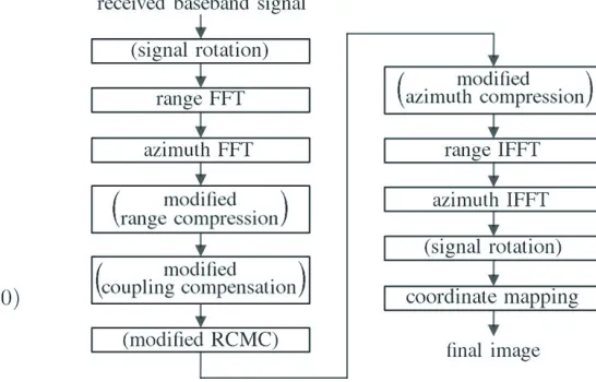
Figure 2 shows a flowchart of the proposed method for high-squint SAR imaging, and the processes enclosed with parentheses are different from those in the conventional RDA [14]. To begin with, the time-domain received baseband signals are rotated to a new coordinate system. Two major processes, range compression and azimuth compression, are implemented in the two-dimensional frequency domain. Four relevant filters are applied in the two-dimensional frequency domain after rotation. At last, the processed signals are rotated back to the original time domain and mapped to the Earth’s surface.
The received baseband signals can be represented as [14]
srb(τ, η) =A0(x, y)F2(η, x, y)we(τ −2Rs(η, x, y)/c)e−j4πf0Rs(η,x,y)/c+jπKr[τ−2Rs(η,x,y)/c]
2
(1)
Figure 1. Flight path of a platform carrying a SAR radar that points at a look angle θ and a squint angle θs towards the target area.
Figure 2. Flow-chart of proposed method for high-squint SAR imaging. The processes enclosed with parentheses are different from those in the conventional RDA [14].
carrier frequency,cthe speed of light, Kr the FM rate of the LFM pulse, we(τ) = rect(τ /Tr) the range envelope with pulse duration Tr, and rect(τ) a rectangular window defined as
rect(τ) =
1, |τ| ≤1/2
0, otherwise (2)
The received baseband signals are stored in a matrix of dimension Na×Nr, where the azimuth sampling number (Na) determines the resolution in the azimuthal direction, and the range sampling number (Nr) should be large enough to record all the scattered signals from the target area. For the convenience of applying the FFT algorithm, both Na and Nr are incremented, respectively, to the nearest integers that are powers of two.
2.1. Rotation in τ-η Plane
Figures 3(a) and 3(b) show the schematic of received baseband signals in coordinates (τ −τ0, η) and (τ −τ0, η), respectively, where τ0 = 2Rs0/c. The number of range samples in Fig. 3(b) can be
(a) (b)
significantly reduced from that in Fig. 3(a). The rotation angleθrbetween these two coordinate systems is chosen as θr= tan−1 2L/VD/cp, where L=ye−yb is the total length of the flight path, and
D = (xc−0)2+ (yc−y
b)2+ (0−h)2−
(xc−0)2+ (yc−ye)2+ (0−h)2 =
R2
0+ [Rs0sinθs+ (0−yb)]2−
R2
0+ [Rs0sinθs−(ye−0)]2
is the length difference between the line segments that connect the BCP to the starting point and the ending point, respectively, of the flight path. Thus, the two coordinates, (τ−τ0, η) and (τ−τ0, η), are related as
τ −τ0
η
=
cosθr −sinθr sinθr cosθr
τ−τ0 η
=
(τ−τ0) cosθr−ηsinθr (τ−τ0) sinθr+ηcosθr
(3) or τ η =
(τ−τ0) cosθr−ηsinθr+τ0 (τ−τ0) sinθr+ηcosθr
=
g(τ, η) h(τ, η)
The received baseband signal originally recorded in the (τ, η) coordinates can be represented in the (τ, η) coordinates as
srb(τ, η) =srb(τ, η)
τ=g(τ,η),η=h(τ,η) (4)
which are interpolated to a unifrom grid in the (τ, η) plane and stored in a matrix of dimensionNa×Nr. For the convenience of applying the FFT algorithm, both Na and Nr are incremented, respectively, to the nearest integers that are powers of two. Without loss of generality, we choose Δτ = Δτ and Δη = Δη.
2.2. Relevant Filters
The range-compression filter used in the conventional RDA is chosen as [1]
Hrc(fτ, fη) =ejπfτ2/Km
where
1 Km =
1 Kr −
λ0R(x)fη2 2D3f2
0Vp2
D = D(fη) =
1− c 2f2
η 4f02V2
p
which is applied in the fτ-fη domain instead of the fτ-η domain as in the conventional RDA. An azimuth-compression filter is chosen as [1]
Hac(fτ, fη) =ej4πR(x)D/λ0
The filter is applied in the fτ-fη domain instead of the τ-fη domain as in the conventional RDA. A range cell migration correction (RCMC) filter is chosen as [1]
Hrcmc(fτ, fη) = exp
j4πR(x)fτ c
1 D −
1 D(fdc)
When the effects of the squint angle are not negligible, a coupling-compensation filter is chosen as [1]
Hcc(fτ, fη) = exp
jπλ0R(x)f 3 τfη2 2D5f3
These four filters are rotated to the fτ-fη plane, based on the similarity property presented in the Appendix, as
Hrc(fτ, fη) = Hrc(fτ, fη)
fτ=g1(fτ,fη),fη=h1(fτ,fη)
Hcc(fτ, fη) = Hcc(fτ, fη) f
τ=g1(fτ,fη),fη=h1(fτ,fη)
Hrcmc(fτ, fη) = Hrcmc(fτ, fη)
fτ=g1(fτ,fη),fη=h1(fτ,fη)
Hac(fτ, fη) = Hac(fτ, fη)
fτ=g1(fτ,fη),fη=h1(fτ,fη)
where the (fτ, fη−fdc) and the (fτ, fη −fdc) coordinates are related by a rotation with the same angle
θr as
fτ fη−fdc
=
cosθr −sinθr sinθr cosθr
fτ fη −fdc
=
fτ cosθr−(fη −fdc) sinθr fτ sinθr+ (fη −fdc) cosθr
or fτ fη =
fτ cosθr−(fη −fdc) sinθr fτsinθr+ (fη −fdc) cosθr+fdc
=
g1(fτ, fη) h1(fτ, fη)
3. SIMULATIONS AND DISCUSSIONS
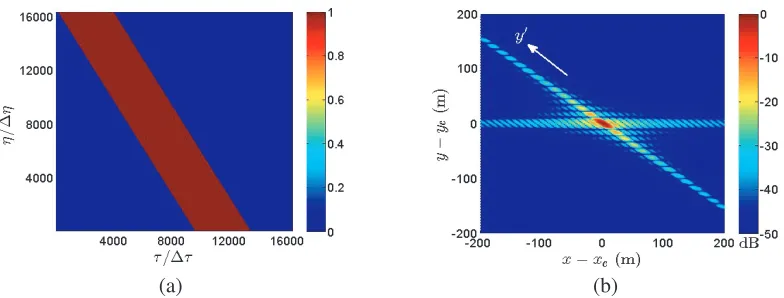
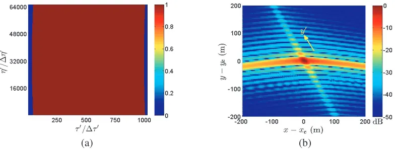
Table 1 lists the parameters of SAR missions used in the simulations [14]. Fig. 4(a) shows the received signal, computed by using Eq. (1), in theτ-η plane. Fig. 4(b) shows the image reconstructed with the conventional RDA, in which local maxima are observed along thex axis and a y axis.
Table 1. Parameters of SAR missions [14].
parameter symbol magnitude unit
effective radar velocity Vp 7,100 m/s
carrier frequency f0 5.3 GHz
chirp pulse duration Tr 40 μs
range chirp rate Kr 500 GHz
bandwidth Br 20 MHz
range sampling rate Fr 96 / 24∗ MHz
range sampling interval Δτ 10.42 / 41.67∗ ns
number of range samples Nr 16,384
azimuth sampling rate Fa 6,800 / 1,700∗ Hz azimuth sampling interval Δη 0.15 / 0.59∗ ms
number of azimuth samples Na 16,384
height of platform h 800 km
look angle θ 19.75 deg.
squint angle θs 60 / 80∗ deg.
(a) (b)
Figure 4. (a) Received signal in τ-η plane and (b) image reconstructed with the conventional RDA, θs= 60◦,Nr= 16,384, Na= 16,384.
(a) (b)
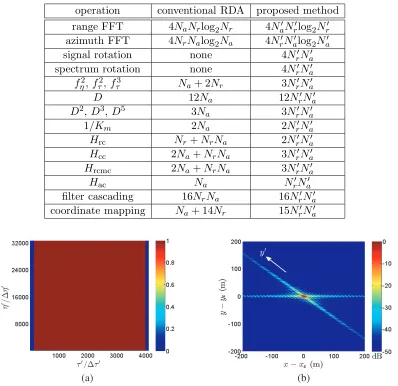
Figure 5. (a) Received signal in τ-η plane and (b) image reconstructed with the proposed method under scheme A, θs= 60◦,Nr = 4,096, Na = 16,384.
(a) (b)
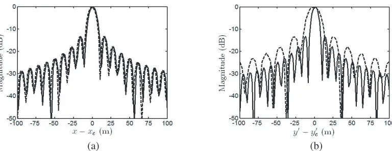
Figure 6. Image profiles along (a) xaxis and (b)y axis, extracted from Fig. 4(b) (- - -) and Fig. 5(b) (———).
Figures 6(a) and 6(b) show the profiles alongxandy axes, respectively, extracted from the images shown in Figs. 4(b) and 5(b). The image reconstructed with the proposed method has similar quality to that with the conventional RDA because the lengths of synthetic aperture are similar.
Table 2 lists the number of multiplications (NOMs) that are required by the proposed method and the conventional RDA, respectively. The memories required by the conventional RDA and the proposed method to store the received signal are on the order of Nr×Na and Nr×Na, respectively.
A second set of sampling numbers are chosen as Nr = 4,096, Na = 32,768, which is labeled as scheme B. The number of range samples is the same as that in scheme A, but that of the azimuth samples is doubled. The NOMs and memory required under scheme B is larger than that under scheme A because the number of azimuth samples of the former is twice that of the latter.
Figure 7(a) shows the received signal in theτ-η plane, transformed by using Eq. (4), and Fig. 7(b) shows the image reconstructed with the proposed method. The number of range samples required by the proposed method is only a quarter that required by the conventional RDA. The number of azimuth samples applied in the proposed method is twice that of the conventional RDA. The reconstructed image appears to have finer spatial resolution in the y direction because the synthetic aperture length is doubled.
Table 2. Number of multiplications in algorithms.
operation conventional RDA proposed method range FFT 4NaNrlog2Nr 4NaNrlog2Nr azimuth FFT 4NrNalog2Na 4NrNalog2Na
signal rotation none 4NrNa
spectrum rotation none 4NrNa
fη2,fτ2,fτ3 Na+ 2Nr 3NrNa
D 12Na 12NrNa
D2,D3,D5 3Na 3NrNa
1/Km 2Na 2NrNa
Hrc Nr+NrNa 2NrNa Hcc 2Na+NrNa 3NrNa Hrcmc 2Na+NrNa 3NrNa
Hac Na NrNa
filter cascading 16NrNa 16NrNa
coordinate mapping Na+ 14Nr 15NrNa
(a) (b)
(a) (b)
Figure 8. Image profiles along (a) xaxis and (b)y axis, extracted from Fig. 4(b) (- - -) and Fig. 7(b) (———).
Table 3. Performance indices of imaging, θs = 60◦.
parameter conventional proposed (scheme A) proposed (scheme B)
IRWx (m) 9.6928 9.6833 9.6826
PSLRx (dB) −13.2521 −13.2418 −13.2406
IRWy (m) 16.3341 16.1536 8.1589
PSLRy (dB) −13.3216 −13.2337 −13.1988
NOM (million) 35,165 11,542 23,622
memory (GB) 4 1 2
Figures 8(a) and 8(b) show the profiles alongxandy axes, respectively, extracted from the images shown in Figs. 4(b) and 7(b).
Table 3 lists the performance indices of reconstructing images, withθs= 60◦. The spatial resolution is characterized by the impulse response width (IRW) of a point target. The images reconstructed with the conventional RDA and the proposed method under scheme A are similar. However, the proposed method takes only 33% of NOMs and 25% of memory as compared to the conventional RDA. The spatial resolutions in thexdirection with the conventional RDA and the proposed method under both schemes are similar, and the spatial resolution in they direction with the proposed method under scheme B is only half that with the conventional RDA. Besides, the proposed method under scheme B takes 205% of NOMs and twice memory as compared to the proposed method under scheme A. However, the former takes only 67% of NOMs and one half memory as compared to the conventional RDA. The proposed method under scheme B turns out to perform better than the conventional RDA in all aspects, including the spatial resolution in y direction, NOMs and memory.
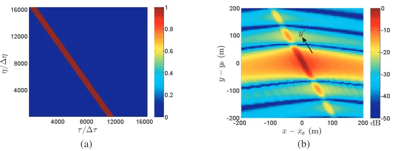
Next, consider a scenario with the squit angle increased to θs= 80◦. Fig. 9(a) shows the received signal, computed by using Eq. (1), in theτ-η plane, and Fig. 9(b) shows the image reconstructed with the conventional RDA.
Figure 10(a) shows the received signal in theτ-η plane, computed by using Eq. (4), and Fig. 10(b) shows the image reconstructed with the proposed method under scheme C, with Nr = 1,024 and Na = 16,384. The number of azimuth samples in the proposed method remains the same as Na =Na, and the number of range samples required by the proposed method is only 1/16 that by the conventional RDA.
Figures 11(a) and 11(b) show the image profiles along x and y axes, respectively, extracted from the images shown in Figs. 9(b) and 10(b).
(a) (b)
Figure 9. (a) Received signal in τ-η plane and (b) image reconstructed with the conventional RDA, θs= 80◦,Nr= 16,384, Na= 16,384.
(a) (b)
Figure 10. (a) Received signal in τ-η plane and (b) image reconstructed with the proposed method under scheme C,θs= 80◦,Nr = 1,024, Na = 16,384.
(a) (b)
Figure 11. Image profiles along (a)xaxis and (b)y axis, extracted from Fig. 9(b) (- - -) and Fig. 10(b) (———).
samples is increased by four times. The image reconstructed with the proposed method under scheme D should be better than that with the conventional RDA and the proposed method under scheme C because the length of synthetic aperture in the former is four times larger than the other two.
(a) (b)
Figure 12. (a) Received signal inτ-η plane, and (b) image reconstructed with the proposed method under scheme D, θs= 80◦,Nr = 1,024,Na = 65,536.
(a) (b)
Figure 13. Image profiles along (a)xaxis and (b)y axis, extracted from Fig. 9(b) (- - -) and Fig. 12(b) (———).
Table 4. Performance indices of imaging, θs = 80◦.
parameter conventional proposed (scheme C) proposed (scheme D)
IRWx (m) 17.3193 17.3099 17.4109
IRWy (m) 66.3484 66.4359 16.3679
PSLRy (dB) −13.2816 −13.2475 −13.1884
NOM (million) 35,165 2,751 11,542
memory (GB) 4 0.25 1
finer spatial resolution in the y direction because the synthetic aperture length is increased by four times.
Figures 13(a) and 13(b) show the image profiles along x and y axes, respectively, extracted from the images shown in Figs. 9(b) and 12(b).
The proposed method under scheme D takes 419% of NOMs and four times of memory as compared to the proposed method under scheme C. However, the former takes only 33% of NOMs and one fourth of memory as compared to the conventional RDA. In summary, the proposed method under scheme D proves to perform better than the conventional RDA in all aspects, including the spatial resolution in y direction, NOMs and memory.
4. CONCLUSION
A modified range-Doppler algorithm (RDA) is proposed to improve the quality of SAR imaging at high squint angles. Several steps in the conventional RDA are modified, and signals in the time domain are rotated to save the memory required to store the received signals. High squint angles of θs = 60◦ and 80◦ are simulated to demonstrate the efficacy of the proposed method in the aspects of spatial resolution, computational load and memory size.
ACKNOWLEDGMENT
This work is partly sponsored by the Ministry of Science and Technology, Taiwan, ROC, under contract MOST 105-2221-E-002-035.
APPENDIX A. SIMILARITY PROPERTY UNDER 2D FOURIER TRANSFORM
A two-dimensional Fourier transform pair can be represented as
H(fτ, fη) = Fη{Fτ{h(τ, η)}}=
∞
−∞
∞
−∞h(τ, η)e
−j2π(fττ+fηη)dτ dη (A1)
h(τ, η) = Fη−1{Fτ−1{H(fτ, fη)}}=
∞
−∞
∞
−∞H(fτ, fη)e
j2π(fττ+fηη)df
τdfη (A2)
The coordinate system (τ, η) is related to the coordinate system (τ, η) via a rotation of angle θas τ η =
cosθ sinθ
−sinθ cosθ τ η
(A3)
Then, the two-dimensional Fourier transform ofh(τ, η) can be derived as
Fη{Fτ{h(τ, η)}} =
∞
−∞
∞
−∞h(τ
, η)e−j2π(fττ+fηη)dτ dη
=
∞
−∞
∞
−∞h(τ
, η)e−j2π[fτ(τcosθ−ηsinθ)+fη(τsinθ+ηcosθ)]
dτdη (A4)
=
∞
−∞
∞
−∞h(τ
, η)e−j2π[(fτcosθ+fηsinθ)τ+(−fτsinθ+fηcosθ)η]dτdη
= H(fτcosθ+fηsinθ,−fτsinθ+fηcosθ) =H(fτ, fη) (A5) wheredτdη =dτ dη and
fτ fη =
fτcosθ+fηsinθ
−fτsinθ+fηcosθ
=
cosθ sinθ
−sinθ cosθ fτ fη
(A6)
A rotation of signal in the time domain leads to a rotation of its spectrum by the same amount.
REFERENCES
2. Chen, S., S.-I. Zhang, H.-C. Zhao, and Y. Chen, “A new chirp scaling algorithm for highly squinted missile-borne SAR based on FrFT,”IEEE J. Select. Topics Appl. Earth Observ. Remote Sensing, Vol. 8, No. 8, 3977–3987, Aug. 2015.
3. Li, Z.-Y., Y. Liang, M.-D. Xing, Y.-Y. Huai, Y.-X. Gao, L.-T. Zeng, and Z. Bao, “An improved range model and omega-K-based imaging algorithm for high-squint SAR with curved trajectory and constant acceleration,”IEEE Geosci. Remote Sensing Lett., Vol. 13, No. 5, 656–660, May 2016. 4. Li, W. and J. Wang, “A new improved step transform algorithm for highly squint SAR imaging,”
IEEE Geosci. Remote Sensing Lett., Vol. 8, No. 1, 118–122, Jan. 2011.
5. Wu, Y., G.-C. Sun, X.-G. Xia, M. Xing, J. Yang, and Z. Bao, “An azimuth frequency non-linear chirp scaling (FNCS) algorithm for TOPS SAR imaging with high squint angle,” IEEE J. Select. Topics Appl. Earth Observ. Remote Sensing, Vol. 7, No. 1, 213–222, Jan. 2014.
6. An, D.-X., X.-T. Huang, T. Jin, and Z.-M. Zhou, “Extended two-step focusing approach for squinted spotlight SAR imaging,” IEEE Trans. Geosci. Remote Sensing, Vol. 50, No. 7, 2889– 3000, Jul. 2012.
7. Xu, H., J. Gao, and J. Li, “A variable PRF imaging method for high squint diving SAR,”Progress In Electromagnetics Research, Vol. 135, 215–229, 2013.
8. Liang, Y., Z.-Y. Li, L. Zeng, M.-D. Xing, and Z. Bao, “A high-order phase correction approach for focusing HS-SAR small-aperture data of high-speed moving platforms,”IEEE J. Select. Topics Appl. Earth Observ. Remote Sensing, Vol. 8, No. 9, 4551–4561, Sep. 2015.
9. Ma, C., H. Gu, W.-M. Su, X.-H. Zhang, and C.-Z. Li, “Focusing one-stationary bistatic forward-looking synthetic aperture radar with squint minimisation method,” IET Radar Sonar Navig., Vol. 9, No. 8, 927–932, Sep. 2015.
10. Moreira, A., “Real-time synthetic aperture radar (SAR) processing with a new subaperture approach,”IEEE Trans. Geosci. Remote Sensing, Vol. 30, No. 4, 714–722, Jul. 1992.
11. Zeng, T., Y. Li, Z. Ding, T. Long, D. Yao, and Y. Sun, “Subaperture approach based on azimuth-dependent range cell migration correction and azimuth focusing parameter equalization for maneuvering high-squint-mode SAR,” IEEE Trans. Geosci. Remote Sensing, Vol. 53, No. 12, 6718–6732, Dec. 2015.
12. Huang, P.-P., W. Xu, and S.-Y. Li, “Spaceborne squinted multichannel synthetic aperture radar data focusing,” IET Radar Sonar Navig., Vol. 8, No. 9, 1073–1080, Feb. 2015.
13. Chen, J.-A., J.-D. Zhang, X.-Y. Qiu, and X.-W. Tang, “A modified subaperture imaging algorithm for squinted sliding spotlight SAR,”IET Int. Radar Conf., Hangzhou, China, Oct. 2015.
![Table 1 lists the parameters of SAR missions used in the simulations [14]. Fig. 4(a) shows the receivedsignal, computed by using Eq](https://thumb-us.123doks.com/thumbv2/123dok_us/1983570.1262169/5.612.188.432.113.270/table-lists-parameters-missions-simulations-shows-receivedsignal-computed.webp)