Modelling And Simulation Of A Unstable Bridge For Winding
Motor Drive Applications
Ansar Shaik & Goutam Barma
1Assistant professor Dept of EEE, St.Peters Engineering College
2Assistant professor Dept of EEE, St.Peters Engineering College
[email protected], [email protected].
ABSTRACT-In this paper a double two-level
inverter is exhibited which decreases the size and weight of the framework for an open end winding enlistment engine drive application. This paper displays a double three stage open end winding enlistment engine drive. The drive comprises of a three stage enlistment machine with open stator stage windings and double scaffold inverter provided from a solitary DC voltage source. The point of this topology is to wipe out the necessity for a massive confinement transformer while accomplishing level yield voltage waveforms. To accomplish multi-level yield voltage waveforms a drifting capacitor bank is utilized for the second of the double extensions. The capacitor voltage is managed utilizing excess exchanging states at half of the primary dc connect voltage. This specific voltage proportion (2:1) is utilized to make a multi-level yield voltage waveform with three levels. The fluffy controller is the most appropriate for the human basic leadership instrument, giving the activity of an electronic framework with choices of specialists. A changed balance plot is utilized to enhance the waveform nature of this double inverter. This paper additionally analyzes the misfortunes in double inverter framework conversely with single sided threelevel NPC converter. By utilizing the fluffy controller for a nonlinear framework takes into consideration a decrease of indeterminate impacts in the framework control and enhance the productivity. By utilizing the reenactment comes about we can break down the proposed strategy.
Index Terms—Field-oriented control (FOC), floating bridge, open-end winding induction machine, fuzzy logic controller, space vector. I.
INTRODUCTION
Multilevel inverters can create a yield voltage waveform having an extensive number of steps with low symphonious bending [1]. They can likewise decrease the weight on the exchanging gadgets as higher levels are incorporated from voltage sources with bring down levels. Multi-level converters have bring down dv/dt what's more, diminished
symphonious bending alongside lower
single sided three stage inverter[14]. A Dual inverter conspire with awry DC connect voltages for the open-end winding enlistment engine is fit for delivering a 4-level PWM waveform with diminished exchanging swell for the engine stage voltage. The conventional double inverter topologies (utilizing two detached dc sources) has been dissected [4], with various space vector tweak plans used to create the multi-level yield voltage waveforms.
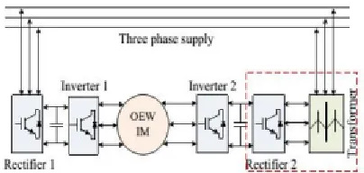
Fig. 1. Conventional open end winding IM drive topology.
A piece chart of a conventional open stage load and converters is appeared in Fig. 1. It is conceivable to utilize a solitary supply for the double inverters with a normal mode disposal system. These topologies utilize particular exchanging mixes that create approach basic mode voltages which scratch off at stack terminals. A decrease in the quantity of voltage levels and lower dc transport voltage use are the primary impediments of this variety of the topology. A regulation system to adjust the control stream between the two inverters in a double inverter framework has additionally been proposed. The skimming capacitor connect topology alongside a reasonable control plan to permit the supply of receptive power was presented. The upsides of double extension inverter with regard to single finished inverters include:
• Improved accessibility since adaptation to non-critical failure can be presented.
• Reduced voltage blocking prerequisites for some of the power semiconductors
• Inverters can share changing occasions prompting
bring down individual gadget recompense
frequencies.
• Reduced exchanging misfortunes for a given yield waveform quality
To make up for supply voltage hang in request to keep the drive operational in steady power mode. This topology utilizes a gliding capacitor connect to balance the voltage hang in rapid machines. To expel the detachment transformer and accomplish multilevel yield voltage waveforms, a double inverter with a coasting capacitor connect is thought about [5]. A circuit topology is broke down which is utilized as a threelevel open end winding acceptance engine drive. This topology utilizes double inverters with just a single DC voltage source at the essential side of the converter. The voltage over the drifting capacitor bank is controlled utilizing the excess exchanging vectors alongside a changed SVM plot which maintains a strategic distance from undesirable voltage levels in the stage voltage waveforms amid the dead-time interims, in this way enhancing the general waveform quality
II. PROPOSED SYSTEM
A. Floating capacitor bridge inverter
Fig. 2. Block diagram of proposed floating bridge topology
Fig. 2 demonstrates a piece chart of the double inverter with a drifting extension and related capacitor. In this strategy the principle converter works in six stage mode and the drifting converter is called molding inverter as it is enhancing the waveform quality. The work depicted in this paper is to control the voltage over the skimming inverter connect capacitor utilizing the repetitive exchanging states, thusly evacuating the requirement for any segregation transformer and enabling the converter to accomplish multi-level yield voltage waveforms. The utilization of a dc connect voltage proportion of 2:1 enables the double extension inverter to deliver up to a three levels in the yield voltage waveform. The control phase of the proposed topology is appeared in Fig.3.
Fig. 3. Power stage of the floating bridge topology (the floating capacitor is charged to half of the main DC link voltage).
B. Principles of operation
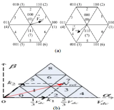
Keeping in mind the end goal to demonstrate how the gliding capacitor can be charged and released the conceivable exchanging states are examined. The space vector outline for the topology is appeared in Fig.4, which is determined by expecting that the two converters as being provided from separated DC sources with a voltage proportion of 2:1.
Fig. 4. Space vector of dual two-level inverter (source ratio 2:1).
Fig. 5. Current flow for different switching state
It can be seen from the Fig. 5 that mixes (11) and (16) will coordinate the current through the positive to negative terminal of the coasting capacitor hence will act to charge the capacitor. It is apparent from Fig. 4 that if the reference voltage is in external hexagon at that point there are just two exchanging mixes in every segment to charge the drifting capacitor. Amid inductive load activity capacitor release rate will be slower and will cause cheating if the reference voltage lies in external hexagon. Additionally, because of absence of charging states, the skimming capacitor will release if the machine is drawing dynamic power. To maintain a strategic distance from these two wonder a limitation must be forced on balance list. Thus the greatest useable number voltage levels over the heap will be decreased to nine (thirteen for secluded sources) alongside a somewhat lower than perfect DC transport voltage usage. Along these lines the gliding capacitor can charge to half of the fundamental DC interface capacitor voltage just if the tweak record (m) is restricted as appeared in condition
The double inverter with a zero arrangement end strategy additionally utilizes single supply with 15% diminishment in DC transport use and can accomplish five-level voltage over the heap
C. Modulation strategy
A decoupled space vector regulation procedure has been utilized for this double inverter skimming connect topology. Exchanging mixes are chosen such that the normal produced voltage for each of the converters is 180 degree stage moved from the other [Fig.6 (a)]. These voltages will at that point include at stack terminal to coordinate general voltage reference [Fig.6 (b)]. The double inverter with unequal voltage sources will demonstrate an alternate trademark, rather than clipping the yield voltage to one of the voltage levels previously or after the dead-time interim voltage levels, it clasps the yield voltage to a few other voltage levels. This is valid for concurrent exchanging for each stage legs of the converters.
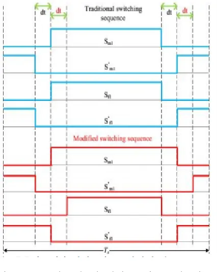
For an illustration, consider stage legs inside green specked line in Fig. 3 for positive load current (current spilling out of primary to drifting converter). On the off chance that the best switches of the legs (Sm1 and Sf1 ) are on at that point the heap current will experience switch Sm1and diode D f1. Presently, if the two legs go to its dead time at the same time the heap current will alter course and will experience diode D ' m1 and diode D f1 . At last at the point when both the converter legs base switches (S ' m1 and S ' f1 ) turned on current will experience diode D ' m1 and switch S ' f1 . Obviously amid deadtime interim, voltage level is diverse to the voltage levels when the dead-time interim. A summed up arrangement is appeared in Fig. 7 for positive stack current.
Fig. 7. Delayed dead-time intervals in both converters when current direction is positive.
It can be seen from the Fig. 7 that the beats are postponed relying upon the exchanging states advances. Table I demonstrates the summed up
answer for positive also, negative load streams to keep away from the undesirable voltage levels.
TABLE I DELAY TIME DEPENDING ON CURRENT DIRECTION
Because of the adjusted exchanging successions, the present course does not change amid the dead-time. The condition of the skimming capacitor will rely upon the current just before the event of dead-time interim. For instance, if the capacitor was charging then it will continue charging when the converter is in dead-day and age. The estimation of deadtime is too little for the any cheat or release to change the capacitor voltage radically.
III. FUZZY LOGIC CONTROLLER
Fig.7.Fuzzy logic controller
The FLC contains three sections: fuzzification, obstruction motor and defuzzification. The FC is portrayed as I. seven fluffy sets for each information and yield. ii. Triangular enrollment capacities for straightforwardness. iii. Fuzzification utilizing persistent universe of talk. iv. Suggestion utilizing Mamdani's, 'min' administrator. v. Defuzzification utilizing the tallness technique.
TABLE I: Fuzzy Rules
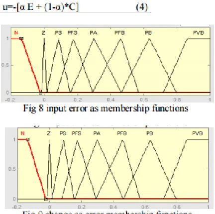
Fuzzification: Participation work esteems are
appointed to the etymological factors, utilizing seven fluffy subsets: NB (Negative Big), NM (Negative Medium), NS (Negative Small), ZE (Zero), PS (Positive Small), PM (Positive Medium), and PB (Positive Big). The Segment of fluffy subsets and the state of participation CE(k) E(k) work adjust the take care of business to suitable framework. The estimation of info mistake and change in blunder are standardized by an info scaling factor.In this framework the information scaling factor has been outlined with the end goal that info esteems are between - 1 and +1. The triangular state of the participation work of this game plan presumes that for a specific E(k) contribution there is just a single overwhelming fluffy subset. The information mistake for the FLC is given as
Inference Method: Several organization strategies for example, Max– Min and Max-Dot have been proposed in the writing. In this paper Min strategy is utilized. The yield enrollment capacity of each lead is given by the base administrator and most extreme administrator. Table 1 indicates govern base of the FLC.
Where α is self-flexible factor which can direct the entire task. E is the blunder of the framework, C is the adjustment in mistake and u is the control variable.
III. SIMULATION RESULTS
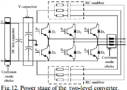
Results from the converter operating as an open loop v/f motor drive are presented to show the converter operation.
A power stage diagram of the experimental two-level converter is shown in Fig.9. The parameters of the converter and machine are provided in Table III.
TABLE III LOAD AND POWER CONVERTERS PARAMETERS
A. Loss comparison
The misfortunes of the proposed double inverter framework are looked at in this segment. Three converter types were chosen, a solitary sided three-level NPC, a double two-three-level inverter with measure up to DC connect voltage proportion and the proposed double inverter topology. The gadget misfortunes were ascertained utilizing semiconductor gadget qualities chose by required blocking voltage and current prerequisites of the topology as displayed in table II.
The misfortune estimations were as far as exchanging and conduction misfortunes for the influence converters and in this examination all other circuit misfortunes were overlooked. Fig. 10 demonstrates the effectiveness at full load (12 KW) with changing exchanging recurrence. It can be seen from the assume that, for this specific stack, double inverter with approach dc connect voltage proportion has preferred proficiency over alternate topologies. The three-level NPC has six additional bracing diodes, hence the misfortunes are higher
The proposed coasting span double inverter has marginally preferable effectiveness over three-level NPC yet is less productive than double inverter with break even with dc connect voltage. The proposed gliding span converter has two unmistakable exchanging designs, one is for charging also, the other is for releasing, along these lines it is hard to keep up the base switch inclusion for exchanging changes.
B. Open loop v/f controlled IM drive
The outcomes for open circle v/f controlled drive are introduced from Fig. 11 to Fig. 12. Fig. 11 demonstrates the no heap voltage, present and drifting DC connect voltage, it can be seen that the drive charges the skimming capacitor to required esteem and the converter accomplishes a multi-level yield voltage waveform. To approve the open circle execution of an IM drive a step stack was connected to the machine, appeared in Fig. 12.
The results presented in Fig. 15 were achieved using the modified switching pulses to avoid unwanted voltage level during the dead-time interval.
A simplified block diagram of the field oriented control system is presented in Fig. 18.
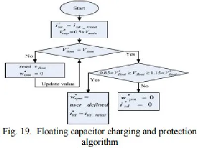
The calculation additionally secures the framework after the speed charge is set. The controller will close down the framework if the capacitor voltage deviation is more than +-15% of the request esteem. A stream graph for this calculation is appeared in Fig. 19.
Beginning charging of the capacitor is exhibited in Fig.20. The adequacy of the polarizing current reference * d I may not be the evaluated esteem. After polarization process was done, a stage reference voltage was connected to demonstrate the
charging flow of gliding capacitor. It can be seen from Fig.20 that capacitor tracks the reference esteem and reaches consistent state inside 1.5 seconds.
Start to finish: gliding capacitor voltage and reference, fundamental dc interface voltage, d-hub current and d-pivot current reference. The capacitor voltage achieves consistent express, a stage request speed reference of 700 RPM was connected. The reaction of the controller is appeared in Fig. 21.
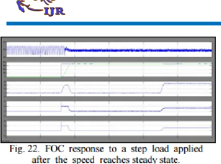
Top to bottom: coasting capacitor voltage, rotor speed, electromagnetic torque, q-hub current and reference q-hub current. The reference torque current iq* is created from the speed circle ventures up instantly to counter the heap torque, as appeared in Fig. 23.
Top to bottom: floating dc link voltage, phase voltage Vaa’, and phase current Ia.
IV. CONCLUSIONS
This paper exhibits a double three stage open end winding acceptance engine drive. The drive comprises of a three stage acceptance machine with open stator stage windings and double extension inverter provided from a solitary DC voltage source. The fluffy controller is the most appropriate for the human basic leadership instrument, giving the activity of an electronic framework with choices of specialists. The proposed framework charges the coasting span capacitor to a proportion of 2:1 as for
fundamental scaffold DC interface voltage
plentifulness. This specific DC interface voltage
proportion enables the converter to accomplish multi-level yield voltage waveform. The coasting DC interface voltage is kept at a steady voltage by the methods for charging and releasing the skimming span capacitor. This is accomplished by choosing between the charging and releasing repetitive conditions of the converter. An open circle v/f control drive was executed to approve the execution of the capacitor control. The dynamic execution of the proposed framework was assessed utilizing a nearby circle field situated controlled engine drive, the outcomes demonstrated that the proposed topology accomplishes multilevel yield voltage waveforms. The point of this topology is to wipe out the necessity for a massive detachment transformer while accomplishing multi-level yield voltage waveforms. By utilizing the fluffy controller for a nonlinear framework takes into consideration a diminishment of unverifiable impacts in the framework control what's more, enhance the productivity. By utilizing the recreation comes about we can show that this topology has potential for applications where measure, weight, misfortunes what's more, repetition are imperative, for instance in aviation, EV or HEV engine drives.
V. REFERENCES
[1] P. Wheeler, L. Xu, L. Meng Yeong, L. Empringham, C. Klumpner, and J. Clare, "A review of Multi-level Matrix Converter topologies," IET Conf. on Power Electron., Machines and Drives PEMD, pp. 286-290, 2008.
[2] J. Rodriguez, L. Jih-Sheng, and P. Fang Zheng, "Multilevel inverters: a survey of topologies, controls, and applications," IEEE Trans. Ind. Electron., vol. 49, pp. 724-738, 2002.
[4] M. Malinowski, K. Gopakumar, J. Rodriguez, and M. A. Perez, "A Survey on Cascaded Multilevel Inverters," IEEE Trans. Ind. Electron., vol. 57, pp. 2197-2206, 2010.
[5] D. Janik, T. Kosan, P. Kamenicky, and Z. Peroutka, "Universal precharging method for dc-link and flying capacitors of four-level Flying Capacitor Converter," IEEE Conf. on Ind. Electron. Soc. IECON, pp. 6322-6327, 2013.
[6] E. C. dos Santos, F. Gulpinar, and E. R. C. da Silva, "Flying capacitor four-level H-Bridge converter," Power and Energy Conf. at Illinois PECI, pp. 1-6, 2014.
[7] E. Levi, "Multiphase Electric Machines for Variable-Speed Applications," IEEE Trans. Ind. Electron., vol. 55, pp. 1893-1909, 2008.
[8] S. Kouro, J. Rodriguez, W. Bin, S. Bernet, and M. Perez, "Powering the Future of Industry: High-Power Adjustable Speed Drive Topologies," IEEE Industry App. Mag., vol. 18, pp. 26-39, 2012.
[9] F. Betin, G. A. Capolino, D. Casadei, B. Kawkabani, R. I. Bojoi, L. Harnefors, et al., "Trends in Electrical Machines Control: Samples for
Classical, Sensorless, and Fault-Tolerant
Techniques," IEEE Ind. Electron. Mag., vol. 8, pp. 43-55, 2014.