Single-Tone Interference Method Based on Frequency Difference
for GPS Receivers
Ruiyan Du1, *, Ling Yue2, Shuai Yao2, Dandan Zhang2, and Yadong Wang2
Abstract—Global Positioning System (GPS) is an excellent application example of satellite communication technology. And it is widely used in navigation, measurement, and time service. However, GPS receivers are vulnerable to unintentional interference or jamming because they rely on external radio frequency (RF) signals. RF interference signals can result in degraded navigation accuracy or complete loss of receiver tracking. Thus, GPS receivers have anti-jamming ability to relieve the effect of interference or jamming. In order to improve the anti-jamming performance of GPS receiver, it is of great theoretical significance and practical application value to study the influence of interference on GPS receiver. To this end, this paper investigates the performance of integrator in the presence of single-tone interference in GPS receiver, and a single-tone interference method based on frequency difference is proposed. Specifically, the analytical relationship between single-tone interference and integrator output is given. Then, it shows that the output of integrator depends not only on the power of single-tone interference but also on the frequency difference between single-tone interference and GPS signal. Finally, the vulnerability of integrator or GPS receiver to the presence of interference increases if the frequency difference satisfies the specific condition. Simulation results show that the proposed method is able to improve the chip error rate in GPS receiver.
1. INTRODUCTION
Global Positioning System (GPS) provides accurate, continuous, worldwide, three-dimensional position and velocity information to users with appropriate receiving equipment [1]. However, GPS receivers are vulnerable to unintentional or intentional interference because they rely on RF signals, and GPS signal has a very low power under the noise floor level. Interference signal can be considered as one of the most disruptive events in the operation of a GPS receiver as the interference signals affect the operation of the automatic gain control and the low noise amplifier in the RF front end, and the acquisition and carrier-code tracking loops are also affected [2].
Single-tone interference is a common interference signal and can degrade the navigation performance of GPS receivers. Therefore, it is of great theoretical significance and practical application value to study anti-jamming algorithm and impact of single-tone interference on GPS receivers. For example, due to the sparsity of single-tone interference in frequency domain, compressive-sensing-based processing algorithm [3] can be used to suppress the single-tone interference. The single-tone interference effect on the performance of acquisition and carrier-code tracking loops in GPS receivers has been addressed by many researchers.
Single-tone interference effects on the performance of GPS receivers are analyzed fromC/N0 after the correlator output and acquisition performance of GPS receiver in [4]. It can be concluded that single-tone interference has a significant effect on GPS receiver performance when it overlaps a spectral
Received 16 December 2018, Accepted 14 February 2019, Scheduled 16 February 2019
* Corresponding author: Ruiyan Du (neu [email protected]).
line of the coarse acquisition code. [5] investigates the performance of the GPS signal acquisition process in the presence of single-tone interference, and novel analytical expressions of both the probability of detection and the probability of false alarm in the presence of single-tone interference are presented.
Effects of single-tone interference on the tracking performance of GPS receivers is investigated in [6], and analytical equations representing delay locked loop (DLL) error and phase locked loop (PLL) error in the presence of single-tone interference are formulated. Performance of DLL in the presence of single-tone interference and additive noise in a coherent direct sequence spread spectrum system with a spreading sequence whose period is one bit long is analyzed. The vulnerability of DLLs to single-tone interference is analytically characterized. The tracking trajectory without noise is obtained, and the tracking error probability distribution function (PDF) with noise is obtained [7]. [8] presents the result of an investigation concerning the performance degradation of a PLL due to single-tone interference and additive white gaussian noise. Analysis is conducted for arbitrary offsets of carrier and interferer signal frequencies relative to the quiescent voltage-controlled oscillator (VCO) frequency in [9]. The results show that loop performance depends not only on the frequency difference between the desired signal and interferer, but also on the frequency offset between the quiescent VCO oscillation and desired carrier. In [10], the effect of single-tone interference on the carrier phase error is studied, and the effects of both interference frequency error and integration time are considered. Yet, the non-coherent integration and interference bandwidth are not considered.
Most researchers above study the acquisition and tracking performance of GPS receiver in the presence of single-tone interference, such as the relationship between single-tone interference and probability of false alarm or the relationship between single-tone interference and DLL error. Other works are ongoing to derive the mathematical expressions for the bit error rate in the presence of single-tone interference [11].
The goal of this paper is to present the impact of single-tone interference on the GPS receiver integrator. In this paper, a single-tone interference method based on frequency difference for GPS receivers is proposed. Firstly, utilizing the properties of autocorrelation function of GPS pseudo random code, the analytical relationship between single-tone interference under different frequencies and integrator output is given. Then, through adjusting the frequency difference between the single-tone interference and GPS signal, the proposed method can maximize the interference component of the integrator output and maximize the bit error rate for GPS receivers. Finally, the theoretical and simulation results show that the proposed interference method can acquire a higher bit error rate.
The rest of this paper is organized as follows. In Section 2, the system model of GPS receiver is presented. The analytical relationship between single-tone interference and integrator output is given, and the proposed single-tone interference method based on the analytical relationship is developed in Section 3. Simulation results are presented to illustrate the effectiveness of the proposed method in Section 4. Finally, Section 5 provides a conclusion to summarize the paper.
2. SYSTEM MODEL
Consider a GPS receiver as shown in Fig. 1 [12, 13], where r(t) represents the received signal, and c(t) and 2 cosω0t denote local pseudo code and local carrier, respectively. x(t) stands for the output of demodulation and despread. 0Tb(·)dt is the integrator in GPS receiver with Tb representing the period of navigation information sequence.
Consider the following representation of received signal. For simple analysis, only GPS signal and single-tone interference signal would be considered while ignoring Gaussian white noise. The received
signal can be given by
r(t) =2Psd(t)c(t) cosω0t+
2Pjcos(ωjt+φj) (1)
where d(t) =±1 and c(t) =±1 are information sequence and pseudo code, respectively; ω0 represents the GPS signal carrier frequency;ωj denotes the interference carrier frequency;φj stands for the phase of jamming signal;Ps and Pj are the power of GPS signal and the power of jamming signal.
The output of demodulation and despread can be written as:
x(t) = 22Psd(t)c2(t)cos2ω0t+ 2
2Pjc(t)cos(ωjt+φj)cosω0t = 22Psd(t)cos2ω0t+ 2
2Pjc(t)cos(ωjt+φj)cosω0t
(2)
The high frequency component in the formula above can be ignored, and the input of integrator has the following form:
y(t) =2Psd(t) +2Pjc(t)cos(ωjt−ω0t+φj). (3) Wheny(t) passes through the integrator, the integrator output yis composed of signal component and interference component. The signal component of integrator output can be expressed
ys= Tb
0
2Psd(t)dt=±2PsTb, (4)
and the interference component can be given by:
yj = Tb
0
2Pjc(t)cos(ωjt−ω0t+φj)dt
=2Pj
Tb
0 ∞
n=0
c(n)gT(t−nTc)
cos(ωjt−ω0t+φj)dt
(5)
wherec(t) =∞n=0c(n)gT(t−nTc) andc(n) represents the pseudo code sequence,gT(t−nTc) the pulse shaping signal, and its period isTc. The integrator outputy has the following form:
y=ys+yj =±2PsTb+2Pj
Tb
0
∞
n=0
c(n)gT(t−nTc)
cos(ωjt−ω0t+φj)dt (6)
where ±√2PsTb is constant, thus, the value of integrator output y mainly depends on interference component yj.
3. ALGORITHM FORMULATION
3.1. Relationship between Frequency Difference and Integrator Output
In GPS, the rate of pseudo code isRc = 1.023 MHz, and the rate of information sequence isRb = 50 Hz. Meanwhile,TcandTbare the reciprocal ofRcandRbrespectively. Thus,Tb/Tc = 20460 can be concluded from parameters above. In Eq. (5), assume that
f(t) = ∞
n=0
c(n)gT(t−nTc)
cos(ωjt−ω0t+φj) (7)
thus, the interference component yj can be rewritten as follows:
yj =2Pj
Tc
0
f(t)dt+· · ·+ kTc
(k−1)Tc
f(t)dt+· · ·+
20460Tc
20459Tc
f(t)dt
=2Pj
20459
k=0
(k+1)Tc
kTc
f(t)dt
In Eq. (8), assume thatyj,k represents the kth component of yj; therefore, the kth component of
yj is given by
yj,k=2Pj
(k+1)Tc
kTc
∞
n=0
c(n)gT(t−nTc)
cos(ωjt−ω0t+φj)dt
=
2Pjck ωj−ω0
sin(ωjt−ω0t+φj)|(kTk+1)c Tc
=
2Pjck ωj−ω0
sin ωj−ω0
fc (k+ 1) +φj
−sin ωj−ω0
fc k+φj
(9)
where fc is the reciprocal of Tc, and ck denotes the kth component of pseudo code sequence in GPS signal.
According to 2 cosαsinβ = sin (α+β)−sin (α−β),yj,k can be further simplified as follows:
yj,k= 2
2Pjck ωj−ω0
cos ωj−ω0
fc
k+1 2
+φj
sin 2πfj −f0
2fc
(10)
then, Eq. (10) is substituted into Eq. (8), and interference component yj has the following form:
yj =2Pj
20459
k=0
(k+1)Tc
kTc
∞
n=0
c(n)gT(t−nTc)
cos(ωjt−ω0t+φj)dt
= 20459
k=0
22Pjck ωj −ω0
cos ωj −ω0
fc
k+1 2
+φj
sin 2πfj−f0
2fc
=2PjTcsin(ΔωTc/2)
ΔωTc/2 × 20459
k=0
ckcos ΔωTc
k+1 2
+φj
(11)
where Δω means the angular frequency difference between GPS signal carrier angular frequency and single-tone interference signal carrier angular frequency, and Δω=ωj−ω0.
For ease of analysis, assume that the angular frequency difference Δωbelongs to 2π×[0,10000] Hz. Under this assumption, sin(ΔΔωTωTc/2)
c/2 can be approximated as 1, and interference component yj can be further simplified as
yj =2PjTc
20460 + 2×R(0)19
i=1
(20−i) cos(i×1023ΔωTc) cosθ (12)
whereR(·) is the autocorrelation function ofck. Tc and R(0) are constant in GPS.
Detailed derivation from mathematical expression (11) to formula (12) is presented in the appendix. Thus, according to Eqs. (6) and (12), the integrator output has the following expression
y=ys+yj =±2PsTb+2PjTc
20460 + 2×R(0)19
i=1
(20−i) cos(i×1023ΔωTc) cosθ (13)
where signal componentys =±√2PsTb is constant. From the above equation, it can be concluded that:
(1) The integrator output is affected by interference component yj because signal component
ys=±√2PsTb is constant;
(2) The interference componentyj of integrator output is affected by the power of interference Pj and the angular frequency difference Δω between single-tone interference and GPS signal;
(4) When the interference power Pj is fixed and angular frequency difference Δω satisfies that Δω = k×2π×1000 Hz,k ∈ N,Δω < 2π×10000 Hz, the interference component takes a bigger value, and the single-tone interference has good interference performance;
(5) The analysis above is based on the assumption that interference frequency is bigger than GPS signal frequency. And interference frequency is lower than GPS signal frequency, and it can acquire the same conclusion.
3.2. Single-Tone Interference Method Based on Frequency Difference
From the analysis above, it can be concluded that when Δω = k×2π×1000 Hz, k ∈ N,Δω <
2π×10000 Hz, the integrator output takes a bigger value.
Based on this conclusion, an effective jamming method based on frequency difference can be summarized as follows:
Step 1. Guarantee that the type of interference signal is single-tone interference and set the power and initial phase of single-tone interference;
Step 2. Due to the effect of doppler shift on GPS signal, the jammer must measure the central frequency of GPS signal;
Step 3. Ensure that the frequency difference between single-tone interference and GPS signal is the integer multiple of 1000 Hz;
Step 4. According to the frequency difference and central frequency of GPS signal, the jammer sets the frequency of single-tone interference;
Step 5. The jammer generates the single-tone interference and transmits the interference signal.
4. SIMULATION RESULTS
In this section, simulation results are provided to illustrate the performance of the proposed method. Assume that the intermediate frequency of the GPS signal after being down-converted by the GPS receiver is 4.092 MHz, and the single-tone interference frequency belongs to 4.092–4.102 MHz. Meanwhile, the signal-to-noise ratio of the GPS signal is equal to −20 dB.
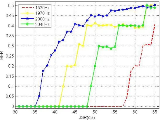
Figure 2 shows the BER of single-tone interference under different jamming-to-signal ratios (JSRs) and different frequency differences. In this simulation, the frequency difference is chosen randomly
Figure 3. The BER under different frequency difference and different JSR.
in 1500–2500 Hz. It can be concluded that BER is a monotonically increasing function of JSR when frequency difference is fixed. And the BER is different in the situation of the same JSR and different frequency differences. For example, when JSR is 45 dB the BER of 2000 Hz-frequency-difference single-tone interference is about 40%, and the BER of other single-single-tone interferences is lower that 40%. Thus, it is obvious that when frequency difference of single-tone interference is equal to 2000 Hz, the BER is bigger, and the single-tone interference has better interference performance. This simulation result is consistent with the conclusion in Section 3 that when frequency difference is equal to integer multiple of 1000 Hz, the single-tone interference has good interference performance.
Figure 3 shows the BER of single-tone interference under different JSRs and different frequency differences. In this simulation, the frequency difference is equal to integer multiple of 1000 Hz. It can be seen that when JSR is fixed, the 7000 Hz-frequency-difference single-tone interference has higher BER than other single-tone interferences. Meanwhile, the 7000 Hz-frequency-difference single-tone interference has lower JSR than other single-tone interferences under the condition of same BER. Therefore, the interference performance of integer multiple frequency difference single-tone interference is different. And 7000 Hz-frequency-difference single-tone interference has better interference performance than other single-tone interferences.
5. CONCLUSION
This paper analyzes the relationship between single-tone interference and integrator output, and proposes a single-tone interference method based on frequency difference. Through theoretical analysis, it can be concluded that the output of integrator depends not only on the power of single-tone interference but also on the angular frequency difference between single-tone interference and GPS signal. When angular frequency difference Δω =k×2π×1000,k∈N, Δω <2π×10000, the integrator output takes a bigger value. Meanwhile, the proposed method can improve the chip error rate for GPS receiver. Simulation results are presented to verify the performance of single-tone interference with higher chip error rate.
ACKNOWLEDGMENT
APPENDIX A.
The aim of this appendix is to present detailed derivation from Eqs. (11) to (12). In Subsection 3.1, assume that the angular frequency difference Δω belongs to 2π×[0,10000] Hz. Under this assumption,
sin(ΔωTc/2)
ΔωTc/2 can be approximated as 1, and Eq. (11) can be further simplified as
yj =2PjTcsin (ΔωTc/2)
ΔωTc/2 × 20459
k=0
ckcos ΔωTc
k+1 2
+φj
≈2PjTc
20459
k=0
ckcos ΔωTc
k+1 2
+φj
=2PjTc
20459
k=0
ck cos(kΔωTc) cos
1
2ΔωTc+φj
−sin (kΔωTc) sin
1
2ΔωTc+φj
=2PjTccos
1
2ΔωTc+φj 20459
k=0
ckcos (kΔωTc)−2PjTcsin
1
2ΔωTc+φj 20459
k=0
cksin (kΔωTc).
(A1) In the above formula (14), to facilitate the representation, let
A=2PjTc
20459
k=0
ckcos(kΔωTc)
B =2PjTc
20459
k=0
cksin(kΔωTc)
(A2)
Thus, Eqs. (14) and (15) lead to
yj =2PjTccos
1
2ΔωTc+φj 20459
k=0
ckcos (kΔωTc)−2PjTcsin
1
2ΔωTc+φj 20459
k=0
cksin(kΔωTc)
=A×cos
1
2ΔωTc+φj
−B×sin
1
2ΔωTc+φj
=(A2+B2) cos
1
2ΔωTc+φj+θ
(A3) whereθ= arctanBA, and φj is the phase of jamming signal.
For simple analysis, assume thatφj is equal to 0 and that ΔωTc
2 is equal to 0 approximately. Thus, the above formula can be rewritten as
yj ≈(A2+B2) cosθ
=
2PjTc20459
k=0
ckcos(kΔωTc) 2
+
2PjTc
20459
k=0
cksin(kΔωTc) 2
cosθ
=2PjTc
20459
k=0
ckcos(kΔωTc) 2
+ 20459
k=0
cksin(kΔωTc) 2
cosθ.
(A4)
According to Eq. (17), assume that
X2 = 20459
k=0
= 20459
k=0
ck2cos2(kΔωTc) + 2× 20458
i=0 20459
j=i+1
cicjcos(i×ΔωTc) cos(j×ΔωTc)
= 20459
k=0
cos2(kΔωTc) + 2× 20458
i=0 20459
j=i+1
cicjcos(i×ΔωTc) cos(j×ΔωTc)
Y2 = 20459
k=0
cksin(kΔωTc) 2
(A5)
= 20459
k=0
ck2sin2(kΔωTc) + 2× 20458
i=0 20459
j=i+1
cicjsin(i×ΔωTc) sin(j×ΔωTc)
= 20459
k=0
sin2(kΔωTc) + 2× 20458
i=0 20459
j=i+1
cicjsin(i×ΔωTc) sin(j×ΔωTc)
thus, the sum of X2 and Y2 can be expressed
X2+Y2 = 20460+2× 20458
i=0 20459
j=i+1
cicj[cos(i×ΔωTc) cos(j×ΔωTc)+sin(i×ΔωTc) sin(j×ΔωTc)]
= 20460 + 2× 20458
i=0 20459
j=i+1
cicjcos(i×ΔωTc−j×ΔωTc)
= 20460 + 2× 20458
i=0 20459
j=i+1
cicjcos [(j−i)×ΔωTc]
= 20460 + 2× 20459
k=1 20458
i=0
cici+kcos(kΔωTc)(i+k≤20459).
(A6) It is known to us that the period of GPS signal pseudo code sequenceck is 1023 and that the period and codomain of its autocorrelation function are 1023 and{1023,−1,63,−65}, respectively.
It is obvious that whenk= 1, 20458i=0 cici+1 is equal to 19×R(1) approximately whereR(·) is the autocorrelation function of ck. Similarly, X2+Y2 can be denoted in the same way, andX2+Y2 is as follows
X2+Y2 = 20460 + 2× 19
i=1
1023i
j=1023i−1022
(20−i)R[mod(j,1023)] cos(j×ΔωTc) (A7)
wheremod(j,1023) means thatjmakes a remainder to 1023, andR(·) can be ignored whenR(·) belongs to {−1,63,−65} because these values are much smaller than 1023.
Thus, Eq. (20) can be rewritten as
X2+Y2 = 20460 + 2×R(0) 19
i=1
(20−i) cos(i×1023ΔωTc), (A8)
and Eq. (21) can now be substituted into Eq. (17) to obtain interference componentyj:
yj =2PjTc
20460 + 2×R(0)19
i=1
(20−i) cos(i×1023ΔωTc) cosθ (A9)
Therefore, Eq. (11) can be written as Eq. (12) by utilizing the property of autocorrelation function
REFERENCES
1. Kaplan, E. D., Understanding GPS Principles and Applications, Artech House, New York, 2006. 2. Bek, M. K., E. M. Shaheen, and S. A. Elgamel, “Mathematical analyses of pulse interference signal
on post-correlation carrier-to-noise ratio for the global positioning system receivers,” Radar Sonar and Navigation Iet, Vol. 9, No. 3, 266–275, 2014.
3. Morabito, A. F., R. Palmeri, and T. Isernia, “A compressive-sensing-inspired procedure for array antenna diagnostics by a small number of phaseless measurements,” IEEE Transactions on Antennas and Propagation, Vol. 64, No. 7, 3260–3265, 2016.
4. Ye, F., H. Tian, and F. Che, “CW interference effects on the performance of GPS receivers,”
Progress in Electromagnetics Research Symposium — Fall, IEEE, 2018.
5. Bek, M. K., S. A. Elgamel, and E. M. Shaheen, “Analysis of the global position system acquisition process in the presence of interference,”IET Radar, Sonar and Navigation, Vol. 10, No. 5, 850–861, 2016.
6. Jang, J., M. Paonni, and B. Eissfeller, “CW interference effects on tracking performance of GNSS receivers,”IEEE Transactions on Aerospace Electronic Systems, Vol. 48, No. 1, 243–258, 2012. 7. Shen, L., F. Chen, and S. Li, “Performance of coherent delay lock loop in the presence of CW
interference and additive noise,” Vol. 1, 236–242, 2006.
8. Chang, Y. and W. Lindsey, “Phase-locked loop performance in the presence of CW interference and additive noise,”IEEE Transactions on Communications, Vol. 30, No. 10, 2305–2311, 2003. 9. Karsi, M. F. and W. C. Lindsey, “Effects of CW interference on phase-locked loop performance,”
IEEE Transactions on Communications, Vol. 48, No. 5, 886–896, 2000.
10. Balaei, A. T., J. Barnes, and A. G. Dempster, “Characterization of interference effects on GPS signal carrier phase error,” 2005.
11. Li, X. Z., Z. C. Zhang, Y. F. Zhan, et al., “Performance research and simulation on DSSS system with short spreading code against single frequency,” International Conference on Wireless Communications, IEEE Press, 2009.
12. Li, H., B. Pei, Y. Huang, et al., “Performance of the direct sequence spread spectrum system with single-tone jamming,” IEEE International Conference on Information Theory and Information Security, IEEE, 2010.