a
Corresponding author: [email protected]
Recent progress on the BIPM watt balance
Hao Fanga, Adrien Kiss, Lennart Robertsson, Estefania de Mirandés, Stéphane Solve, Thomas Lavergne, Alain Picard and Michael Stock
Bureau International des Poids et Mesures, Pavillon de Breteuil, 12 bis Grande Rue, 92312 Sèvres Cedex, France
Abstract. We present the recent progress on the BIPM (Bureau International des Poids et Mesures) watt balance. The existing apparatus was transferred to the dedicated new laboratory with better thermal and vibrational conditions. The apparatus is fully operational in air. An improvement by a factor of three was achieved on the S/N ratio of both the voltage-to-velocity and force-to-current ratios. The fabrication of the parts of the new magnet is completed and its assembly is finished.
1 Introduction
The kilogram is the last remaining base unit of the International System of Units (SI) which is still defined by a material artefact: the international prototype of the kilogram (IPK). It is planned that the kilogram will be redefined based on a fundamental constant of nature, the Planck constant, instead of a material artefact which suffers from long-term drift and which is not universally available [1]. The BIPM, as custodian of the IPK, is developing a watt balance to ensure its long-term ability to realize the expected new definition of the kilogram.
2 BIPM watt balance
A watt balance establishes a link between a macroscopic mass and the Planck constant by comparing mechanical power to electrical power and by making use of two electrical macroscopic quantum effects, the Josephson effect and the quantum Hall effect [2, 3]. The BIPM watt balance has the unique capability of implementing both the conventional two-phase and the simultaneous measurement schemes [4, 5]. The novel simultaneous approach of the BIPM watt balance makes the experiment less sensitive to some of the factors limiting the conventional approach. Moreover, comparison of both measurement schemes will provide a better understanding of the systematic errors unique to each approach and so increase confidence in the results. However, the simultaneous mode requires the separation of an unwanted resistive voltage drop from the induced voltage which is the quantity to be measured.
The first watt balance experiment was conducted in a non-ideal environment inside a temporary laboratory. In this experiment, the watt balance was mounted on an
optical table without any vibration isolation and was composed of simplified components and measurement facilities. The fully operational apparatus was capable of producing Planck constant values with a type A uncertainty of 10−6 and a type B uncertainty of the order of 10−5 [6]. The type A uncertainty was limited mainly by the poor laboratory environment whereas the type B uncertainty was limited mainly by alignment capabilities.
In parallel, development of an improved apparatus operated in a more favourable environment has well advanced. In particular, a vacuum chamber was installed in a dedicated new laboratory with improved thermal conditions and vibration reduction.
This paper summarizes the improvements made to the experimental apparatus since its transfer to the new laboratory. Development of some additional elements and measurement facilities is presented. In particular, fabrication and assembly of the new magnetic circuit are reported.
3
Experimental apparatus
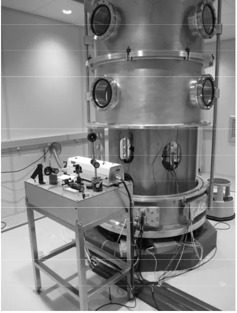
The existing apparatus was transferred to and assembled inside the vacuum chamber in the dedicated new laboratory early 2013 (figure 1). Actually, the next, improved apparatus had already been fabricated and was ready for assembly, except the new magnet. As some elements need to be directly mounted on the new magnet, it was thus impossible to install the improved version immediately. In the meantime, the existing apparatus has been installed to repeat previous measurements and to evaluate the improvement due to better environment.
access to the different parts of the apparatus. A massive inner support structure has been designed to minimize horizontal tilts and displacements of the suspension with respect to the magnetic circuit. The chamber sits on a massive concrete block (64 tons) via a large granite block. The granite block provides a plane surface, on which the magnetic circuit can be slid after suspending it using compressed air, allowing its centring and tilting during the alignment procedure. To reduce the transmission of seismic and acoustic vibrations to the watt balance set-up, passive anti-vibration dampers are used between the granite block and the vacuum chamber whereas the experimental apparatus is decoupled from the chamber by flexible connections.
Figure 1: The current apparatus inside the vacuum chamber located in the new laboratory. A temporary table is being used to mount the laser source for the three interferometers.
As the vacuum chamber is designed for the future improved apparatus, modifications were thus made to accommodate temporarily the existing apparatus inside. Some components of the future version are already used, in particular, a new vacuum-compatible force comparator. The apparatus is fully operational in air.
The commercial new force comparator has a capacity of 12 kg with a resolution of 10 μg. It was fully characterized in air on an independent small concrete block isolated from the floor. The conversion function between the mass value and the raw voltage output, as a function of temperature, has been determined. The sensitivity to tilting has been evaluated by tilting the weighing cell at several known angles and by recording the related change in mass reading. We obtained coefficients of 0.8 μg/μrad and 7.0 μg/μrad along the
longitudinal and transverse axis, respectively. The dynamic response of the weighing cell has also been estimated by means of a piezoelectric actuator acting on the loading pan of the balance. Periodical voltages were applied to the actuator to generate modulated forces pushing on the weighing cell. The results led to the conclusion that the weighing cell should be able to follow changes in the electro-magnetic force on the coil during its travel inside a magnetic field with a relative non-uniformity of 10-4, at a velocity larger than 80 mm/s, much larger as the actually used velocity of 0.2 mm/s.
4
Measurements and results
4.1 Voltage-to-velocity ratio
4.1.1 Noise
Measurements carried out in the new laboratory showed several large low frequency noise peaks, in particular a peak at 18 Hz whose amplitude reached as much as 10 % of the velocity of the moving coil (0.2 mm/s). This confirms seismic measurements, carried out successively on the concrete block and the surrounding floor, which showed that the concrete block damps the vibration noise above 50 Hz but has negligible effect at lower frequencies. We also observed large-band noise on the velocity data of about five parts in 104 in relative terms. This could be explained by the significant cyclic non-linearity error of the interferometer measurements, see next section.
4.1.2 Non-linearity error on velocity measurement
balance. At the same time, alignments of some easily and independently adjustable elements in the watt balance were improved to reduce this effect as far as possible. The non-linearity effect was reduced to 2 parts in 104 which correspond to a peak-to-peak non-linearity error of about 3 nm.
This error was then further reduced mathematically. Several methods have been evaluated and two have been found to be easily implemented in practice. The first consists of simply averaging the position data for several periods of the non-linearity error. In the second technique, the data are fitted using a polynomial function of time. The position value at a given measurement time are then deduced from the fit. The two methods gave similar results in the present measurement conditions.
4.1.3 Improvement
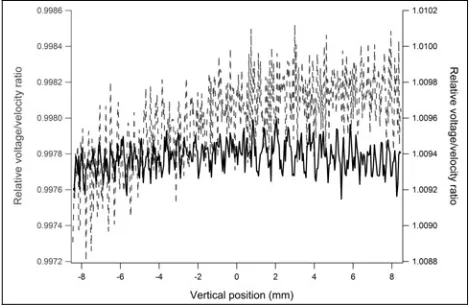
The voltage-to-velocity ratio (U/v) is compared with that obtained in the old laboratory (figure 2). The results are deduced from a single measurement with the coil moving upwards. We mention that the new measurements were carried out using a bifilar coil [6] instead of a single working coil. The wire length of each winding of the bifilar coil is thus approximately half of that of the normal working coil. An improvement in the standard deviation of the residuals (after fitting the magnetic profile) by a factor of more than two was achieved on the U/v ratio. This was mainly due to the reduction of the non-linearity error on the velocity measurement. The ratio has a relative standard deviation of 8 x 10⁻⁵. The two curves do not represent the same magnetic profile due to the change in absolute vertical position of the coil inside the magnet between two measurements. Absolute position sensing is not yet available in the present apparatus.
Figure 2: The relative voltage-to-velocity ratios deduced from one up measurement. The thin dashed line represents the ratio obtained in the old laboratory and solid line in the new laboratory.
At present, the signal-to-noise (S/N) of the U/v ratio is limited by a 28 Hz noise peak which needs to be better understood and minimized in the future. The residual non-linearity error might be a potential limiting error source especially in our particular case where the velocity is very small compared to most watt balances and the vibration noise is very large. Therefore, we plan to
develop a new interferometer having a very small non-linearity error. Imperfect cancelling of the vibration noises in the U/v ratio and the resolution of the present phase detection system are other sources of error.
4.2 Force-to-current ratio
In the BIPM watt balance, both the force-to-current (F/I) and the voltage-to-velocity ratios are measured at the same time while the coil moves. For the U/v ratio, the large vibration noise, common to both signals, is significantly reduced when calculating the ratio of the two. However, for the F/I ratio, the vibration noise influences only the force determination, not the current, so that it cannot be cancelled out by calculating the ratio and needs to be reduced or carefully corrected.
The force values obtained in the new laboratory were less noisy than before and especially better correlated with the coil acceleration, generated by the vibrations. The following figure shows the raw force (mass) and the acceleration values obtained from a single up measurement. The coil acceleration data have been obtained from the three interferometers. A correction due to the acceleration was then applied to the raw force data. An improvement by a factor of two was then achieved on the S/N ratio of the force data (F/I ratio). We note that the current driven through the coil has a high stability better than 10-7 in relative terms. However, the corrected data still shows significant residual variation due to the imperfect correlation between the force change detected by the force comparator and the acceleration measured on the moving coil. Work needs to be continued to better understand and correct this acceleration effect due to vibration.
Figure 3: An example of the force and the acceleration results obtained from one up measurement. The upper graph displays the acceleration. The lower graph represents the change in the related mass value before (thin dashed line) and after applying the correction due to the acceleration (solid line).
noisiest units were identified. The noisiest one has already been removed. The replacement of the two others by new quieter units is underway.
5
Developments
In parallel to the work on the experimental apparatus, development of the improved elements and measurement facilities has progressed.
5.1 New magnetic circuit
The flux source will be two discs of Sm2Co17, having a remanent magnetization of 1 T, with opposite magnetization. They will be inserted in a closed magnetic circuit made of high permeability FeNi-alloy of austenitic structure [4]. A horizontal field with radial symmetry is obtained in the horizontal symmetry plane. The air gap will be 13 mm wide with a mean diameter of 250 mm. The flux density in the gap, at the position of the coil is about 0.5 T. Since the gap is completely surrounded by material with high magnetic permeability, it should be efficiently screened against external magnetic fields. The flux density in the gap shall be constant in the vertical direction, so that the force on the moving coil does not change more than about 100 ppm. The system is symmetrical about the horizontal symmetry plane so that no linear slope of the field profile is expected. The inner and outer poles are 84 mm and 80 mm high to minimize the vertical components of the field.
The uniformity of the flux density in the gap depends critically on the uniformity of its width, that is on the accuracy of machining and assembly of the pole pieces. The required uniformity demands that the width of the gap is constant within 6 μm. The upper part of the magnet needs to be removable to give access to the coil. For the coil suspension, holes are needed in the upper part of the yoke.
The magnet discs and the parts of the yoke have been manufactured by external collaborators. The Sm2Co17 disks with an outer diameter of 216 mm have been assembled from nine segments, each, and mounted between two FeNi discs, because this material is not available in such large dimensions. The outer and inner poles of the yoke have been machined to very tight tolerances to guarantee a uniform width of the gap. The cylindricity of the outer pole has been determined as 1.4 μm, that of the inner pole as 0.6 μm. The position of the central yoke element, carrying the inner pole face, with respect to the outer part, carrying the outer pole face, is determined by three titanium columns (not shown in figure 4), with identical length. A test assembly of the yoke, without the magnets, was carried out, and a uniformity of the gap width in the vertical direction of about 1 μm was demonstrated with capacitive sensors.
The assembly including the Sm2Co17 magnets is complicated due to the large magnetic forces, of up to about 10 kN. An assembly device has been built which allows assembling all elements, by guaranteeing centering of the inner and outer pole to within 20 μm. The whole circuit has very recently been assembled. The
measurement of the dimensional uniformity of the gap width with capacitive probes is on-going. The uniformity of the flux density in the gap will then be determined by means of a Hall probe.
Figure 4: The magnetic circuit, consisting of two discs of Sm2Co17 and a closed FeNi yoke. The flux density in the central plane, where the gap is located, is horizontal and radial.
5.2 Other developments
We have successfully validated an original dynamic alignment mechanism based on push–pull piezoelectric actuators. This system will allow compensation of undesirable deviations of the moving coil from a purely vertical movement during its travel in working mode and decorrelation between the tilts and the translations of the coil in alignment mode.
The functioning and the performance of the system were evaluated on an independent set-up. A mechanical friction damper has been added inside the structure to reduce unwanted large angular oscillations of the system. Servo-controls of the horizontal displacements and tilts have been achieved either independently or simultaneously. A small correlation between linear and angular displacements was observed when both servo-controls were in operation. The position stability over 1 minute (duration of travel of the coil over its total path) was better than 0.5 μm and the angle stability was within 0.5 μrad. An improved version of the system is being fabricated at the BIPM workshop before its future integration inside the watt balance experiment.
Work has advanced to apply the alignment technique already developed to the watt balance [8]. As a first step, the electric plane of the working watt balance coil as well as an adjustable mirror fixed onto the coil were aligned to be horizontal with an total uncertainty of about 150 μrad. A home-made auto-collimation system was used for the alignment of the mirror because of its small size. As this reference mirror is still too large to be placed inside the magnet gap, the next step will be to transfer its alignment to a smaller mirror directly glued on the watt balance coil. The coil will finally be integrated in the watt balance to align the magnetic field.
damaged and could not be repaired. New arrays have been tested for its replacement. At the same time, the current source has been improved to avoid the trapping of magnetic flux. It is foreseen to test the whole system in the watt balance end 2013.
6
Conclusions
Progress has been made to further develop the BIPM watt balance experiment. The current apparatus is fully operational again in air after its transfer to the new. The non-linearity error of the interferometer measurements was reduced. An improvement by a factor of three was achieved on the S/N ratio of both the voltage-to-velocity and force-to-current ratios. Development of several additional and improved elements and measurement facilities for an improved version of the apparatus has advanced. In particular, the fabrication and the assembly of the new magnetic circuit are finished.
We will start soon to build the improved version of the apparatus which will comprise several new key elements such as the alignment mechanism, a mass exchanger as well as an automated device for in-situ calibration of the force comparator.
References
1. M. Stock, Metrologia, 50, R1 (2013).
2. B.P. Kibble, Atomic Masses and Fundamental Constants, vol. 5, J.H. Sanders and A.H. Wapstra, Eds. New York: Plenum, 545 (1976).
3. A. Eichenberger et al., Metrologia, 40(6), 356 (2003).
4. A. Picard, et al., IEEE Trans. Instrum. Meas., 56(2), 538 (2007).
5. A. Picard, et al., IEEE Trans. Instrum. Meas., 60(7), 2378 (2011).
6. H. Fang, et al., IEEE Trans. Instrum. Meas., 62(6), 1491 (2013).