accounting energy distribution along horizontal and vertical
enclosure structures
A.E. Neea
Tomsk Polytechnic University, Lenin Str., 30, 634050 Tomsk, Russia
Annotation. Mathematical modelling of unsteady convective-conductive heat exchange in premises, heated by infrared radiant heater is passed. Heat flux density from infrared radiant heater was calculated accounting energy distribution along horizontal and vertical building envelope. Comparison between zonal method and Lambert’s law radiant energy distribution was done.
Introduction
The expedience of radiant heating systems using is described in detail in many papers both Russian [1] and foreign scientists [2]. At the same time, the experimental study of premises heating by gas infrared radiator (GIR) requires considerable means consumption, so in some cases using mathematical modelling methods is more preferred.
Mathematical modelling of conductive – convective heat transfer in the conjugate formulation [3,4] is a priority for such problems, because models based on the heat balance of premises [5] do not show the dynamics of heat transfer completely. Introduced algorithm for calculating the radiant heating systems [6] does not account convective streams of air and heat conduction of enclosure structures. In study [7] a calculation of GIR heat conduction only with multi – layer roof construction was done. In the mathematical model of conductive – convective unsteady heat transfer process of radiant heating one of the internal borders of closed rectangular area in the conjugate formulation [8] was assumed that the heat flux was evenly distributed along the inner surfaces.
The aim this study is the numerical simulation the unsteady process of closed rectangular area radiant heating in conjugate formulation with accounting energy distribution along horizontal and vertical enclosure structures.
a Corresponding author:
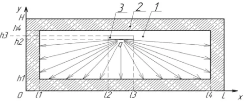
Figure 1. Solution domain: 1– air; 2 – enclosure structures; 3 – gas infrared radiator (symbolic notation).
Problem formulation and solution method
The boundary value problem of conjugate heat transfer in area consisting of six rectangular subdomains (Fig.1) is considered. Heat insulation conditions were adopted at external borders. At internal borders “air – enclosure structures”, “air – heat supply object” are the fourth type boundary conditions.
Assumptions that thermal properties of air and enclosure structures don’t depend on temperature are introduced. Flow regime is laminar. The air is considered as an incompressible Newtonian fluid satisfying the Boussinesq approximation and absolutely transparent for thermal radiation. Total radiant flux coming from the GIR can be represented as the sum of heat fluxes values of which were determined by zonal method as shown in [6].
Investigated process is described by the unsteady Navier – Stokes equations for the air and the heat conduction equation for the building envelopes. Motion, continuity and energy equations were reduced to dimensionless form. As the scale distance was chosen the length of the gas cavity.
To reduce the system of equations to dimensionless form were used the following relations: X=(L−x
2·l1); Y = y
(L−2·l1);= t t0;U =
u Vnc;V =
v Vnc;=
T −T0 Th−T0;=
0
;=
0 ;
V0=
g··(Th−T0)·(L−2·l1); 0=VncL; 0= Vnc
L ;
where: x,y – dimensional coordinates, m; X,Y – dimensionless coordinates; (L – 2l1) – the gas cavity length along x axis; t – time, s;t0 – time scale; – dimensionless time; u,v – velocities along x,y axes respectively; U, V – dimensionless velocities; Vnc– velocity scale (natural convection velocity);
– dimensionless temperature; T0– air, buildings envelopes and radiant infrared heater temperatures in initial time; Th – temperature on infrared heater surface;– stream function, m2/s;0 – stream function scale; – dimensional analog of ; – velocity vortex, 1/s; 0 – velocity vortex scale;
– dimensional analog of.
Dimensionless equations of Navier – Stokes and energy in variables “vorticity– stream function
– temperature” are as follows [3,8]:
*
* +U
*
*X +V
*
*Y =
Pr
Ra· ∇2+ 1 2
*1
*X , (1)
∇2= −, (2)
*1
* +U
*1
*X +V
*1
*Y =
1 √
Ra·Pr · ∇ 2
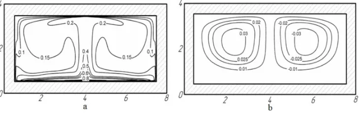
Figure 2. Fields of temperature (a) and stream function (b) (=3600) with Lambert’s law radiant energy distribution.
*2
*F o2 = ∇ 2
2. (4)
where:∇– Nabla operator; Ra – Rayleigh number; Pr – Prandtl number; Fo – Fourier number. The initial conditions for the system of Eqs. (1)–(4):
1(X,Y, 0)=0; 1(X,Y, 0)=0; 1(X,Y, 0)=0; 2(X,Y, 0)=0; The boundary conditions for Eqs. (1) – (4):
at the outer boundaries of solution domain:
X=0, X=1, 0< Y ≤1 : *2(X,Y,)
*X =0;
Y =0, Y =1, 0< X≤1 : *2(X,Y,)
*Y =0.
at internal interfaces “solid wall – air”, parallel to the axis OX:
=0, *
*Y =0,
i=j,
*i
*Y =
j i
·*i
*Y +Kiqk, gde
i=1, 2 j =1, 2 k=1, 5.
at internal interfaces “solid wall – air”, parallel to the axis OY:
=0, *
*X =0,
i=j,
*i
*X =
j i ·
*i
*X +Kiq6, gde
i=1, 2
j =1, 2
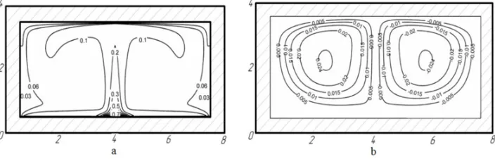
Figure 3. Fields of temperature (a) and stream function (b) (=3600), zonal method (decomposition of enclosure structures inner surfaces into 5 zones).
Figure 4. Fields of temperature (a) and stream function (b) (=3600), zonal method (decomposition of enclosure structures inner surfaces into 11 zones).
The results of the numerical simulation
The following values of dimensionless criteria were assumed: Rayleigh number Ra=106; Prandtl number Pr=0.71; Kirpichev numbers Ki1=60, Ki2=10,Ki3=9,Ki4=8, Ki5=6,Ki6=3. The problem is solved for three variants of modeling of radiant heat transfer. The results are shown on pictures 2, 3 and 4. Axes dimensions were plotted in meters.
Comparing the fields of temperature and stream function a conclusion can be done, that the motion nature of the air flow is the same for the three considering variants. Temperature fields differ from each other because the proportion of energy absorbed by individual surfaces is different. Figures 3and 4 show that a significant energy proportion comes to the border y=h1,l2< x < l3, parallel to the GIR. In the case of Lambert’s law radiant energy distribution with increasing angle of radiation from GIR the intensity decreases smoothly.
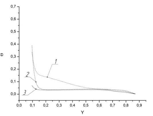
Temperatures distribution along theyaxis atx=0.4 andx=4 in cavity filled with air are shown on Figs.5and6.
Figure5shows that the temperature drop along of the gas cavity height is smoothly to the interface “air – enclosure structure”. Maximum temperature gradient is reached at the line 3. It can be explained that the intensity of radiant energy directed to the lower horizontal boundary is considerably less than in the other cases (lines 1, 2).
Figure 5. Temperature distribution along the y axis atx=0.4 in cavity filled with air (1 – Lambert’s law; 2 – zonal method (5 zone); 3 – zonal method (11 zone)).
Figure 6. Temperature distribution near the solid wall along the y axis at x=0.4 in cavity filled with air (1-Lambert’s law; 2 – zonal method (5 zone); 3 – zonal method (11 zone)).
Conclusion
[5] L. M. Dyskin, V. V. Shivanov Heat Balance of the Premises with Gas Rays Heating// Izv. Vys. Uchebn. Zaved.. Stroit.. – 2007. – No. 8. – P. 62 – 65
[6] V. V. Bukhmirov, S. A. Krupennikov, and Yu. S. Solnyshkova, Algorithm of calculating systems of radiant heating of rooms, Vestn. Ivanovsk. Gos. Énerg. Univ., Issue 4, 23–25 (2010)
[7] N. I. Kurilenko, R. R. Davlyatchin Heat exchange between gas infra-red radiator and multilayered roof construction // Vest. TGASU.- 2009.- No. 4.- P. 132 – 141
[8] G.V. Kuznetsov, V.I. Maksimov, T.A. Nagornova, N.I. Kurilenko, G.Ya Mamontov Heat transfer under heating of a local region of a large production area by gas infrared radiators // Journal of Engineering Physics and Thermophysics. – 2013. – V. 86. – No. 3. – P. 519 – 524
[9] V. M. Paskonov, V. I. Polezhaev, and L. A. Chudov, Numerical Simulation of the Heat and Mass Transfer Processes [in Russian], Nauka, Moscow (1984)