ABSTRACT
:Stress corrosion cracking (SCC) is an environmentally assisted cracking phenomenon leading to degradation of mechanical properties of material under the combined action of stress and corrosive environment. Out of several series of aluminums alloys, 7xxx series alloys are highly susceptible to SSC and have specific application in aerospace, military and structural industries due to their superior mechanical properties. Present work brings out clear understanding of SSC mechanism and critical metallurgical issues affecting SSC behavior. Further effect of SSC on life of aluminum alloy is investigated experimentally and attempts made to enhance life of material with the aid of different heat treatments.
Keywords: Scanning electron microscope, Stress corrosion cracking, 7xxx aluminum alloy.
1. INTRODUCTION
Aluminum 7xxx series alloy material is the light engineering material used for various applications due to their attractive mechanical properties. Such alloys are facing a problem in their susceptibility to environmentally assisted cracking (EAC) in a variety of environments such as chlorinated solutions, oxides etc. Aluminium 7075 T651 grade material provides a good resistance to general corrosion due to rapidly formed Al2O3 film with the exposure to the environment and they are highly prone to pitting corrosion in aggressive environments (NaCl salt solution). High strength Al alloys are readily susceptible to another form of localized corrosion known as stress corrosion cracking (SCC). Out of the all series of Al alloys, SCC is most common in 2xxx, 7xxx and 5xxx (high Mg content) series Al-alloys. A large number of aircraft component failed by SCC and these series alloys contributed to more than 90% of the service failures of all high-strength aluminum alloys. The main factor which has vital effect on the SCC behavior is the alloy composition. The composition of the material affects the formation and stability of a protecting film on the surface of the alloy. These alloying elements may influence the strength, grain boundaries, grain size and orientation, grain-boundary segregation, and residual stresses within the material. So this work focuses on studying SSC mechanism and revealing best possible ways to mprove SCC resistance.
DESIGN AND DEVELOPMENT OF CONSTANT LOAD SET UP
AND STUDY SCC BEHAVIOR OF AL ALLOY
Mr. Sandeep Gaikwad
1, Mr. G. A. Kadam
22.
LITERATURE
REVIEWDetailed literature review is carried out in order to have a knowledge of research work which has been already taken place in this field. V.S. Raja et.al [1] had studied the stress corrosion cracking behaviors of Mg-Mn in various concentrations of NaCl environment. Objective of this work was to find out the role of chlorides on the alloy strength of an Al alloy. Bharat. S. Padekar et.al [2] reported that using constant load test the study of stress corrosion cracking behavior was studied with high concentration of Mg(OH)2solution. The Mg has a high strength alloy and light in weight and it has many applications therefore study of SCC behavior on Mg and its resistance to stress corrosion cracking using both slow strain rate and constant load method was studied. And found out its behavior using s SEM microstructures. A. C. Umamaheshwer rao et.al tried to clarify the effect of constituent alloying elements in various heat-treated conditions on SCC behavior. Further, review was made for improving the SCC resistance using thermo mechanical treatments and by surface modifications of 7xxx alloys.Burleigh T.D. et.al [4] investigated that Stress corrosion cracking has an important role in material degradation and that affects strength. And it has a sudden failure of the material without warning. SCC can be observed only when alloy susceptibility, aggressive environment (NaCl for aluminium alloys) and tensile stress are present simultaneously. Gerhardus H. Koch et.al [5] reported that the laboratory testing plays an important role in observing SCC failure. Since there is no generalized analytical approach to allow prediction of combinations of material and environment that result in SCC, the avoidance of SCC has to be based either on past experience or on testing in the laboratory. Paul A. Rometsch et.al [6] had studied the effect of different heat tratments on ultimate tensile strength, yield strength of material. AdeyemiDayoIsadarea et.al [7] had studied annealing and age hardening heat treatment process and their effect on 7075 Al alloy along with the variation of mechanical properties and microstructural behavior with respect to heat treatment. H. Alvandia et.al [8] examined three types of crack morphology of a fractured surface of the material to find out ways of failure. The microstructure shows three types of a fractured surface such as dimple structure, trans granular structure and inter granular structure. Onoro.J. et.al [9] had presented a research work on the mathematical model of stress corrosion behavior of aluminium alloy and compared them with experimental results using various tests. A.Mukharjee et.al [10] focused on study of corrosion behavior of aluminium using microstructure examination and studied the mechanical properties of the materials using strain rate tests. M. Bobby kannan et.al [11] brought out the general understanding of the SCC mechanism and the specific metallurgical issues affecting the SCC behavior of Al alloys. The developments took place so far with regard to alloying and heat treatment of aluminium alloys for enhanced SCC resistance is discussed. design and development of test rig Experimentation for this work require test rig which consists of following components. Design of each component is detailed below.
3. DESIGN OF SPECIMEN
The aluminium 7075 T651 grades is used for flat specimen as this is widely used and prone to SCC. Design of specimen is selected from the ASTM , E8 standards.
Thickness of flat specimen = 4 mm. Gauge area = 24 mm2
Flat specimen length = 189 mm.
Fig.1
. Two dimensional view of specimen3.1 DESIGN OF SPRING
Material: Oil hardened and Tempered Spring steel, Sut = Ultimate tensile strength = 1050 N/mm2 Load on spring = W = 15000 N
Assume spring index = C = 5
Shear stress= τ = ( 8KWC ) / ( Π d2 ) …..1 But stress factor or Wahl’s factor = K = [ (4C–1)/(4C-4) ] + [ (0.615/C) ] K = 1.3105
shear stress = 525 MPa as per ISO Recommendations, from equation 1
525 = ( 8 x 15000 x 5 ) / ( Π x d2 ) gives d = 21.83 = 22 mm
but C = D / d
D = 5×22 = 110 mm δ = 8WD3 N / Gd4 ..…2 N = 4.77 = 5
For square and ground end Nt = N+2 = 5+2 = 7 Solid length = Nt × d = 7×22 = 154 mm.
Total Gap = 6×1.5 = 9
Assume maximum deflection = 40 mm
Free length = Solid length + Total Axial gap + d = 154 + 9 + 40 = 203 mm
Pitch = free length / (Nt – 1) Pitch = = 33.33 mm
Considering manufacturing constraints, dimensions taken are as listed below.
Dimensions Value
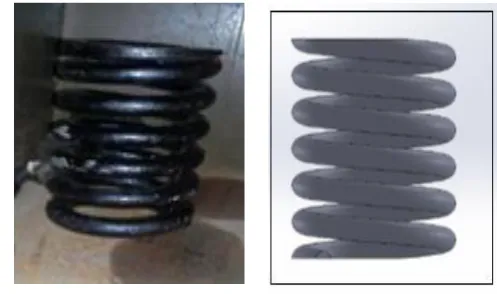
Fig.
2
. Manufactured spring Wire diameter (d) 22 mmMean coil diameter (D) 88 mm No. of coils ( Nt) 07
Pitch (p) 34 mm
Free length 204 mm
Stiffness from UTM 595 N/mm
Solid length 154mm
Table 1
Final Dimensions of spring 3.2 DESIGN OF POWER SCREWMaterial: Medium carbon steel (0.35-0.45 %C) 45C8 EN8 Tensile stress = = 4 W / Π dc
2
= 4 x 15000 / (Π x dc 2
) = 400/5 dc= 15.45 mm The screw is also subjected to torsional shear stress, therefore selecting d up to 30 mm from design data. Select a single start square thread l = p = 6 mm
As per design data,
For 30 mm diameter, pitch = 6 mm dm =d – 0.5 p
dm = 30 - 0.5×6 = 27 mm
Assume tanϕ = µ = 0.15 gives ϕ = 8.53076 As , tan α = l / Π dm gives α = 4.046 = 4 x 15000 / (Π x 24 2 ) = 33.15 N/mm2 τ = 16 Mt / Π d3
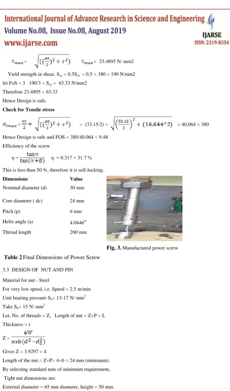
τ = 16 * 45.18 / (Π * 243 ) = 16.644 N/mm2 Check for shear stress
= = 23.4895 N/ mm2 Yield strength in shear, Ssy = 0.5Syt = 0.5 × 380 = 190 N/mm2 let FoS = 3 190/3 = Ssy = 63.33 N/mm2
Therefore 23.4895 < 63.33 Hence Design is safe. Check for Tensile stress
= = (33.15/2) + = 40.064 < 380
Hence Design is safe and FOS = 380/40.064 = 9.48 Efficiency of the screw
η = η = 0.317 = 31.7 % This is less than 50 %, therefore it is self-locking.
Dimensions Value
Fig. 3.
Manufactured power screw Nominal diameter (d) 30 mmCore diameter ( dc) 24 mm
Pitch (p) 6 mm
Helix angle (a) 4.0446
Thread length 260 mm
Table 2
Final Dimensions of Power Screw
3.3 DESIGN OF NUT AND PIN Material for nut - Steel
For very low speed, i.e. Speed < 2.5 m/min Unit bearing pressure Sb= 13-17 N/ mm
2 Take Sb= 15 N/ mm
2
Let, No. of threads = Z, Length of nut = Z×P = L Thickness = t
Z =
Gives Z = 3.9297 = 4
Length of the nut = Z×P= 4×6 = 24 mm (minimum). By selecting standard nuts of minimum requirement, Tight nut dimensions are:
Check nut dimensions are: External diameter = 65 mm diameter, height = 25 mm. Here, the Pin is used to fix the test specimen with top pull rod and bottom fixing rod. Shear stress = =
=
For static loads FOS is small, usually it takes 1.5 to 2. But due to hole, stress concentration comes into role so FOS increased from 1.5 to 2.5
Select FOS = 2.5
= = 94 N / mm2 = d = 14.25 mm ~ 20 mm
Considering crushing Failure of pin in eye, The Crushing stress of pin in eye is calculated as = =188 N / mm = Force / Projected area
= = as l = 4 mm thickness of specimen
= 182.9268 < 188 N / mm2 The Pin is safe as crushing failure.
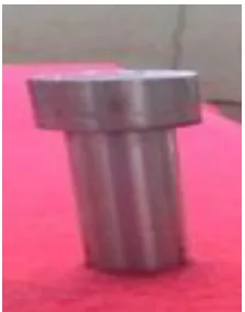
Fig. 4.
Manufactured pin 3.4 DESIGN OF COLUMNAs we have, Crushing load =P = (4 Π2 EI/Le2 )
Minimum moment of inertia = /64
As there are 04 pillars provided,
load is equally distributed = 20 KN/4 = 5KN From above equations , d = 6.92 mm Take d = 25 mm as per availability. Radius of gyration is given by K =R/ √2
K = 8.8388/2 = 4.4
For both ends fixed Le = l/2 = 320/2 = 160 mm Slenderness ratio = le/k = 160/4.4
S.R.= 36.10 < limit for Mild steel . Hence Design is safe.
The pillars are manufactured 50 mm extra on each side with external thread as 19 mm and mating nut fixed to the threaded part of the pillar on both ends for locking.
3.5 DESIGN AND DEVELOPMENT OF CORROSION CELL AND CHEMICAL SOLUTION
The cell is made up of Acrylic sheet .The cell is cut in required dimensions and joint is made by small screw and nut, and leakage is arrested by M seal applying on inside and outside at corner of the cell. Solution of 10% weight of NaCl is made in chemistry lab. For 1 liter of distilled water 100 gram of Nacl powder is taken and mixed thoroughly and that solution is used as the chemical solution inside the corrosion cell. Stop watch is used for time measurement.
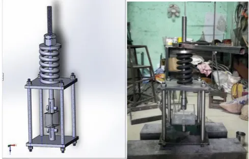
3.6 EXPERIMENTAL TEST RIG ASSEMBLY Final assembly of test rig is as shown,
Fig. 5
. Experimental test rig experimental details
3.7 MATERIALS USED
Aluminum 7075 material is used to prepare specimen.
Chemical Component weight %
Aluminum 87.10 - 91.40
Copper 1.2 - 2.0
Chromium 0.18 - 0.28
Magnesium 2.10 -2.90
Iron Maximum 0.5
Zinc 5.10 -6.10
manganese Maximum 0.3
silicon Maximum 0.2
Tin Maximum 0.4
Table 3
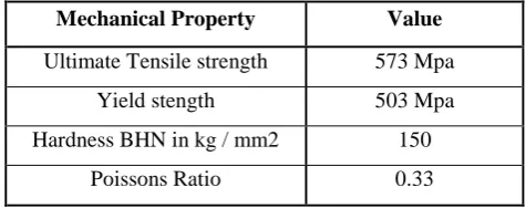
Composition of Aluminium alloy 7075 T651 GradeMechanical Property Value
Ultimate Tensile strength 573 Mpa
Yield stength 503 Mpa
Hardness BHN in kg / mm2 150
Poissons Ratio 0.33
Table 4
Mechanical properties of Al alloy 7075 T651 Grade Sample specimens are prepared from Al 7075 material.3.8 HEAT TREATMENT PROCESS – ANNEALING AND PRECIPITATION HARDENING
To investigate effect of stress corrosion cracking on heat treated specimen, samples are heat treated. Annealing and precipitation hardening is carried out on specimen, one each.
Annealing:
It is carried out at about 450°C, keeping sample at this temperature for 3 hours followed by controlled cooling at rate of 10°C per hour till 300°C and then air cooled.
Precipitation hardening:
The Sample is heated at a temperature of 480 °C in a furnace and holding it at this temperature for 2 hours followed by rapid quenching in cold water. Then precipitation hardening treatment (age hardening) is carried out by heating samples to below solvus temperature around 130 °C, holding them at this temperature for 5 hours and then air cooling to room temperature.
3.9 TEST PROCEDURE
applied yield load was checked from actual UTM tested load–deflection curve and found out the respective deflection and reading of deflection in mm applied to set up during specimen loading.
As we have,
= Cross section area of specimen = 6 mm x 4 mm=24 mm2
So, F = 366 x 24 = 8784 N = 8.8 KN
From results of spring compression test plotted on Load - displacement curve, To apply 8.8 KN load, spring should get deflected through 15 mm .Similarly all calculations are made throughout the testing of specimen.
4 RESULTANDDISCUSSION
As per test procedure, testing is carried out and corresponding results and discussions are presented subsequently.
4.1 ENDURANCE OF MATERIAL
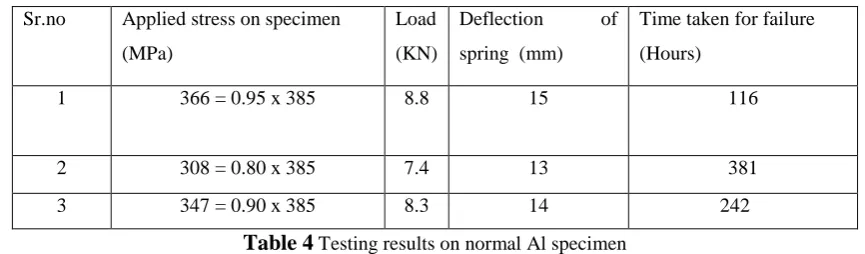
Tensile testing in presence of corrosive environment (10 % NaCl ) gives results as enlisted in table 5. Sr.no Applied stress on specimen
(MPa)
Load (KN)
Deflection of spring (mm)
Time taken for failure (Hours)
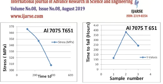
1 366 = 0.95 x 385 8.8 15 116
2 308 = 0.80 x 385 7.4 13 381
3 347 = 0.90 x 385 8.3 14 242
Table 4
Testing results on normal Al specimenFig. 6. Variation of applied stress with life span of specimen Fig.7.Variation of life span of specimen with Sample number
The crack initiation and crack propagation are the two parts of failures of material. After crack initiation, crack propagates at faster rate on application of higher load than that of on lower one. Third sample is tested at 0.9 ×Yield stress and time it takes till failure is about 242 hours. In this failure of the sample the load reduced to 0.95 to 0.9×Yield stress. So time till failure increased from 116 hours to 242 hours.
Similarly testing is then carried out on heat treated specimen. After application of heat treatments like annealing and precipitation hardening, material properties and SCC testing results are shown in table 6 and 7.
Heat treatment Yield
strength in MPa
Ultimate strength
in MPa
Brinell Hardness
number in kg/mm2
Rockwell
Hardness No.
Standard Al Specimen
properties as per ASTM. 477-510 540-573 152 90
Actual Al specimen 385 409 130 80
Annealing 111.166 121 64.6138 25
Precipitation hardening
408 477 164 90
Table 5
Mechanical Properties of Aluminium Specimen Testing results are tabulated as below.Heat treatment Applied
stress (MP ) Load applied
Deflection of spring ( mm)
Time to fail ( Hours)
Annealing 107=0.95 x
112
2.6 KN 4.2 144
Precipitation hardening 388=0.95 x 408
9.3 KN 16 Specimen didn’t fail even at
higher load ( tested till 600 hours)
The annealed specimen takes more time to fail in corrosive environment under a tensile stress as compared to without heat treated specimen at stress equal to 0.95 x yield stress. Due to annealing the material elongation is more under low load. The microstructure of annealed fracture specimen shows dimple structure and less trans granular or inter granular structure as shown in the fig 10.
The higher hardness value developed by age hardening attributes to precipitation of coherent and finely dispersed MgZn2 phases which serves as foreign atom or inclusion in the lattice of host crystal in solid solution. This causes more lattice distortion and alloy harder. Precipitates particles act as obstruction to dislocation movement and strengthen the heat treated alloy.
In the precipitation hardening heat treatment, even though the load is above the yield stress in corrosive environment the sample does not fail due to SCC. Due to age hardening the material properties such as yield, ultimate stress and the hardness values goes on increasing and the material becomes more resist to stress corrosion cracking. Therefore, it is difficult to fracture during plastic deformation. The SCC behavior is along or across the grain boundary, i.e. Intergranular or Transgranular manner. Therefore, it increases the SCC resistance and aluminums sample takes more time to fail under a sustained tensile stress with the corrosive NaCl environment. In this experiment, precipitation hardened specimen didn’t fail even after 600 hours.
4.2 ANALYSIS of fractured surface of FESEM
Steps followed for analysis of fractured surface on SEM are : 1. Sample preparation as per standard of the SEM.
2. The sample is cut nearly 2 to 3 mm from the fractured surface .This cross section smoothly filed and then the sample is numbered and sent to SEM
3. Image analysis of the fractured surface
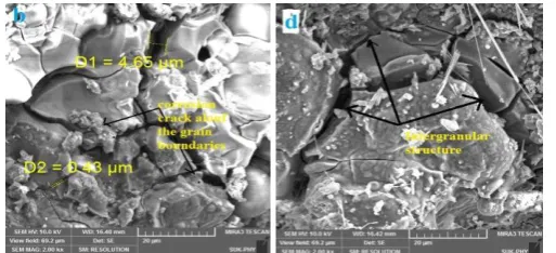
Fig.8
SEM image of fractured surface (applied stress = 107 MPa, Time to fail = 144 hours ) Natural EnvironmentFig.09.
SEM image of fractured surface (applied stress = 366 MPa, Time to fail = 166 hours ) Corrosive Environment.Fig 09 shows the fractography of Al specimen, indicates the dimple structure and remaining microstructures with high magnification indicates the SCC is along the grain boundaries due to presence of corroded material along the grain boundaries of the aluminum alloy so failure time decreases due to corrosive environment.
5
CONCLUSIONS
SCC is prone to corrosive environment and tensile loading acting simultaneously. Life of Al 7075 alloy reduces substantially due to SCC in corrosive environment compared to than that of normal working environment. Heat treatment enhances SCC resistance by incorporating the microstructural alterations. Annealing improves grain size ie. grain coarsening, so dislocation movement increases leading to higher ductility. Hence it takes larger time to fail. Precipitation hardening produces finely dispersed particles. Fine sized precipitates impede the dislocation movement by forcing the dislocation to cut in between or go around the grain boundaries. Hence by restricting dislocation movement, Al alloys are strengthened.
61
R
EFERENCES[1] V.S. Raja,Bharat. S. Padekar “Role of chlorides and hydrogen embrittlement of Mg-Mn wrought alloy” corrosion science 75 , pages 176-183 , 2013.
[2] Bharat. S. Padekar , V.S. Raja , Lyon paul , R.K.Singh Raman “Stress corrosion cracking of a recent rare- earth containing magnesium
alloy, EV31A, and a common AL- containing alloy, AZ91E.” corrosion science 71 , Pages 1-9, 2013.
[3] Donghai Du, Kai Chen, Huilu“Effects of chlorides and oxygen on stress corrosion cracking of cold worked 316/316L austenitic stainless
steel in high temperature water” corrosion science, volume 110, pages 134-142 , September 2016.
[4] Burleigh T.D., “The postulated mechanisms for stress corrosion cracking of aluminum alloys – a review of the literature ”, Corrosion,
47, p.89, 1980-1989.
[5] J, Toribo, E. Ovejero “Failure analysis of cold drawn prestressing steel wires subjected to stress corrosion” ,pp.645-661, Dec. 2005.
[6] Paul A. Rometsch, Yong Zhang, Steven Knight, “Heat treatment of 7000 series Al alloys- some recent development”, Trans. Nonferrous
Met. Soc. China 24, 2014.
[7] Knight S, Birbils N, Muddle B, Trueman A, Lynch S.Correlations between intergranular stress corrosion cracking, grain boundary
microchemistry, and grain boundary electrochemistry for AL–Zn–Mg–Cu alloy Corrosion Science, ,52: 4073-4080, 2010.
[8] Turnbull A, Horner D,Connoly B. Challenges in modeling the evolution of stress corrosion cracks from pits .Engineering Fracture
Mechanics, 76: 633-640, 2009.
[9]Andrés Valiente ,Mariángel Pérez Guerrero ,Mihaela Iordachescu “New testing method for assessing the cracking sensibility of stressed tendon rods in aggressive environments” Engineering failure analysis 68, 244-253, 2016.
[11] A.C.Umamaheshwar, M.Govindraju.,V.Vasu and K.V.Saisrinath(2016) “Stress corrosion cracking behavior of 7xxx aluminum alloys A literature review” Trans. Nonferrous Met. Soc. China 26, 1447-1471, 2016.
[12] Speidel O.M. , „„Stress corrosion cracking of aluminum alloys‟‟, Metall.Trans. A, 6A, p. 631, 1975.
[13] Li WANG ,Hongmei Li ,Zhenmao CHEN , “Reconstruction of Deep Stress Corrosion Crack Based on a Multi-objective Optimization
Evaluation from Eddy Current Testing Signals .” 86-29-82668736
[14] Wang xianli ,Xu jing,qi Chunling , “Whole process analyses of concrete cover corrosion cracking based on virtual crack model.”
Fourth International Conference on Digital Manufacturing & Automation, Institution of traffic and construction engineering,132013
china,2013.
[15] Lynch S.P. „„Mechanisms of environmentally assisted cracking in Al-Zn-Mg single crystals”,corros.sci.,22,p 925,1982.
[16] Holroyd N.J.H. and Hardie D. , „Strain-rate effects in the environmentally assisted fracture of a commercial high-strength aluminium
alloy (7049)‟, Corros. Sci., 21, p. 129,1981.
[17] N.D. Tomashov, V.N. Modestova, in: I.A. Levin (Ed.), Inter crystalline Corrosion and Corrosion of Metals under Stress, Great
Britain, 1962.12. L. Fairman, J.M. West, Corrosion. Sci. 5 , 711–716, 1965.
[18] Bobby-Kannan M., Raja V.S., Raman R. and Mukhopadhyay A.K. , “Influence of multistep aging on the SCC behavior of Al alloy
(7010)”, Corr59, p.881, 2003.
[19] G.Silva and B.Rivolta et.al. “study of SCC behavior of 7075 Al alloy after one step Aging at 163oc., journal of material engineering
and performance , ISSN 10599495,DOI 10.1007/s11665-012-0221-4.
[20] Adeyemi DayoI sadareaand Bolaji Aremob, “Effect of Heat Treatment on Some Mechanical Properties of 7075 Aluminium Alloy”, a
review of the literature 2013”,Materials Research ,16(1): 190-194,2013.
[21] H. Alvandia, and K. Farmanesha, “Microstructural and Mechanical Properties of Nano/Ultra-Fine Structured 7075 Aluminum Alloy
by Accumulative Roll-Bonding Process” Procedia Materials Science, 17 – 23, Nov 2015.
[22] Shaiful Rizam Shamsudin, “Role of scanning electron microscope (SEM) in metal failure analysis” Proceeding of MINT technical
convention 2005, ESSET, Bangi,15-16, 2005.
Corresponding authors:
Mr. Sandeep D Gaikwad 1, Mob. 8983028048 P.G.Student ( Mechanical Design Engineering ) Department of Mechanical Engineering, SKNSIT Lonavala, Maharashtra.
Savitribai Phule Pune University, Pune, Maharashtra, India. Email address : [email protected] Prof. G. A. Kadam 2 , Mob : 9975815120
Professor ( Mechanical Design Engineering ) Department of Mechanical Engineering, SKNSIT Lonavala Maharashtra.