4G UPLINK & OTHER DEVELOPMENTS IN
INTERLEAVE-DIVISION MULTIPLE-ACCESS
(IDMA)
Mr. Paurush Bhulania
1, Mr. Gagan Minocha
2, Ms. Richa Sharma
31
Asst. Professor-I, ECE, Amity University, Noida,
2
Asst. Professor-I, ECE, Amity University, Noida,
3
PG students, Amity University, Noida.
ABSTRACT
Efficiency and adaptivity play a major role in the design of fourth-generation (4G) wireless systems. 4G
systems should be bandwidth efficient, power efficient, and allow for low complexity transceivers. The systems
should be flexible with respect to data rate (link adaptation), data reliability (QoS), and service provisioning.
Moreover, they should operate on frequency-selective and fast-fading channels.
In this paper, a system for the 4G uplink based on Interleave-Division Multiple Access (IDMA) is presented,
which fulfils the mentioned requirements. Cross-layer issues are addressed & we outline several new
developments related to interleave-division multiple-access (IDMA).Our discussion encompasses the
applications of IDMA in multiple-input multiple-output, relay and ad hoc environments. We demonstrate the
flexibility and robustness provided by IDMA.
Keywords
:
Multiple Access Interference (MAI), Interleavers, Multiple-Input Multiple-Output
(MIMO), Channel State Information (CSI), Uplink & Interleave-Division Multiple-Access (IDMA).
I INTRODUCTION
DS-CDMA is a popular transmission technique already applied in 2G (IS-95), 2.5G (cdma-2000), and 3G
(UTRA FDD, UTRA TDD, TD-SCDMA) systems. Distinct data streams dm are distinguished by different
spreading sequences. Forward error correction (FEC) coding is typically done before interleaving and spreading.
Conventionally, the same FEC encoder and the same interleaver is used for all data streams dm. If the
arrangement of interleaving and spreading is reversed, the data streams are distinguished by different
interleavers. This special case of DS-CDMA is called code-spread CDMA [1], chip-interleaved CDMA
(cI-CDMA) [2], or interleave-division multiple access (IDMA) [3] in the literature. We will use “IDMA”
throughout this paper. As an alternative to the described re-arrangement between interleaving and spreading,
IDMA may be interpreted as DSCDMA without spreading. In effect, for DS-CDMA systems it has been shown
by Viterbi that the highest power efficiency can be achieved by low-rate codes [4], and it has been proven by
Verd´u and Shamai that the highest bandwidth efficiency can be achieved by low-rate codes as well [5].
A second alternative is to interpret IDMA as a special form of trellis-coded modulation In this paper, we outline
several new developments related to IDMA. In particular, we focus on the following issues:
• We demonstrate the flexibility and robustness provided by IDMA.
• IDMA in multiple-input multiple-output (MIMO), relay and ad hoc environments.
II IDMA IN MIMO CHANNELS
IDMA is also a promising technique for applications over MIMO channels. Two methods are outlined below for
situations with and without channel state information (CSI) at the transmitter, respectively.
Interleave-Division-Multiplexing Space-Time Coding If the transmitter has no CSI, the interleave-division multiplexing space-time
(IDM-ST) scheme [6] shown in Fig. 1 can be employed to exploit the diversity provided by the use of multiple
antennas. In Fig. 1, the information is first encoded by SCM and then segmented in a serial to parallel converter
into N equal-length sections to be transmitted from N antennas simultaneously. The layer specific random
interleaving in SCM ensures that the signal can be detected using an iterative receiver [6].
Figure 1. Transmitter structure of a superposition IDM-ST code.
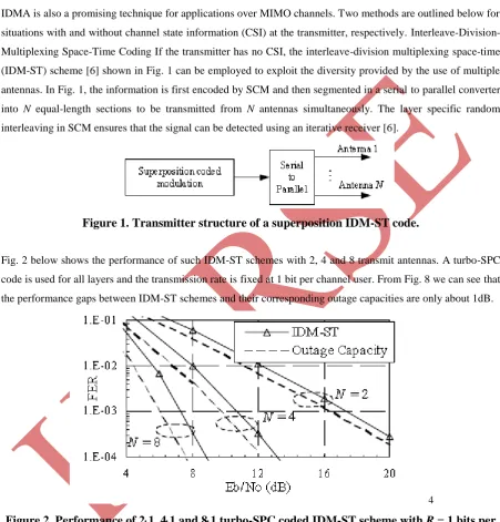
Fig. 2 below shows the performance of such IDM-ST schemes with 2, 4 and 8 transmit antennas. A turbo-SPC
code is used for all layers and the transmission rate is fixed at 1 bit per channel user. From Fig. 8 we can see that
the performance gaps between IDM-ST schemes and their corresponding outage capacities are only about 1dB.
4
Figure 2. Performance of 2
1, 4
1 and 8
1 turbo-SPC coded IDM-ST scheme with
R
= 1 bits per
channel use.
2.1Maximum Eigen mode Beam forming
For a multi-user MIMO channel with full CSI at the transmitters, the optimal transmission scheme involves the
joint optimization of the transmission power (or rates) and the input covariance matrices for all users, which is
rather complicated. A simplified approach is the so-called maximum eigenmode beamforming (MEB) method
[7], in which each user is only allowed to transmit in the direction of its maximum eigenmode. This method,
asymptotically optimal when the number of users in the system is sufficiently large. Fig. 3 compares the
required average transmitted sum-power of an optimal MIMO system with equal rate constraint for each user
and that achieved by the MEB approach.. From Fig. 3, we can see that when K ≥ 2, the performance loss of the
MEB approach is negligible. Fig. 3 also indicates that significant power saving can be achieved due to
multi-user gain.
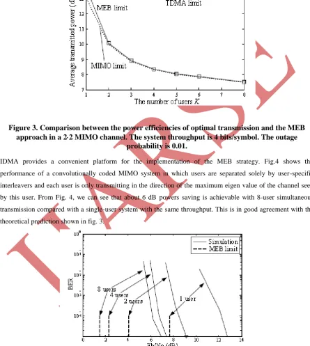
Figure 3. Comparison between the power efficiencies of optimal transmission and the MEB
approach in a 2
2 MIMO channel. The system throughput is 4 bits/symbol. The outage
probability is 0.01.
IDMA provides a convenient platform for the implementation of the MEB strategy. Fig.4 shows the
performance of a convolutionally coded MIMO system in which users are separated solely by user-specific
interleavers and each user is only transmitting in the direction of the maximum eigen value of the channel seen
by this user. From Fig. 4, we can see that about 6 dB powers saving is achievable with 8-user simultaneous
transmission compared with a single-user system with the same throughput. This is in good agreement with the
theoretical prediction shown in fig. 3.
Figure 4. Simulation performance of an MEB-IDMA system over a 22 single-cell fading channel for K = 1, 2, 4, and 8,
respectively. The system throughput is KR = 4 bits/symbol. The outage probability is 0.01. The corresponding MEB limits
III 4G UPLINK PROPOSAL
3.1. IDMA-Based Transmission System
For the uplink, an efficient yet simple multiple access schemes supporting a high number of active users is
needed. Using IDMA, we can handle a large number of users, each of them using a different interleaver.
Interleavers are easy to find and for long blocks even random interleavers may be used. We propose a
transmitter and receiver structure as published in [8] and shown in Fig. 5. After low-rate encoding, the
interleaving is done with a layer specific interleaver ¼m. Assuming a linear channel, the impact of the
transmission medium can completely be represented by the vector h = [h0, ..., hL], where hl denotes the l-th
coefficient of the equivalent discrete-time inter symbol-interference channel model with memory length L. At
the receiver side the individual layers, which are experiencing multilayer interference (MLI), are detected by a
low complexity multilayer detector (MLD). An iterative (turbo-like) receiver that exchanges extrinsic
information between the MLD and the decoder (DEC) can be applied. This receiver structure is nearly optimal,
of low complexity, and provides reliable soft outputs. The MLD uses channel estimates delivered by a channel
estimator. We propose a pilot-layer aided channel estimator (PLACE) [9] (see Section 3.5). Given the
log-likelihood values from the m-th layer passed by the decoder after the last iteration, an evaluation module is used
to calculate an estimate of the bit error rate (BER) of the m-th layer. The BER estimate is used for soft link
adaptation (Section 3.3).
In [11] it is shown how to improve the error performance of IDMA by means of a hybrid scheme with
orthogonal code multiplexing and IDMA (OCDM/IDMA). An optional extension of IDMA based on this
approach is depicted in Fig. 1. The data stream of one user is parallelized in multiple layers. Different encoders
are used for the single layers. All layers of one user share one interleaver.
It is also possible to perform the spreading over multiple sub-carriers to obtain an MC-IDMA system. This is an
interesting alternative to IDMA for systems with a huge number of sub-carriers, or an extension of existing or
planned MC-CDMA systems [12], [10].
3.2. Soft Link Adaptation
One enormous advantage of the low-cost IDMA-receiver considered in [13] is the inherent reliability of soft
output information. In [8] an adaptation strategy based on the soft outputs is described. Besides of delivering
hard decisions after the final iteration, the receiver in Fig. 1 calculates estimates of the BER in an evaluation
module. The evaluation module compares the estimated BER with the predefined target BER Pt. Since the BER
degrades with increasing number of layers because of increased MLI, the number of layers transmitted in the
next block is decreased at the transmitter side if the estimated BER is higher than the target BER. If the
estimated BER is below the target BER, the transmission power can be reduced. It was shown in [11] that the
proposed iterative receiver is appropriate for the suggested adaption strategy.3.4D. High Bandwidth and
3.4Power Efficiency. In Section IV, it is shown that without adaptive power allocation a spectral efficiency of
about 3.75 bits/s/Hz can be reached for one transmit antenna. With adaptive power allocation, a spectral
In conjunction with the proposed adaptation strategy, a continuous operation near the theoretical limit can be
achieved. However, due to soft link power adaptation the mobile device always uses minimum power for
transmission which results in long battery life.
3.3. Pilot-Layer Aided Channel Estimation
The receiver under investigation needs reliable channel estimates. In IDMA it is suitable to use pilot-layer aided
channel estimation [16], where one layer for every user carries training symbols for channel estimation. This is
especially useful for the uplink as the channel for every mobile station is different at a base station. An
allocation of a pilot layer has been shown to achieve good estimates for the whole block length even for rapidly
changing frequency-selective fading channels.
3.4. Multiple Antenna Systems
Multiple antenna systems are a key technology for 4G. In [15] IDMA has been extended to multiple antennas
with good results. The extension of IDMA to MIMO systems is easy because the superposition of the different
layers at the transmitter side and their separation at the receiver side is done anyway. Therefore, neither special
design is needed nor further increase in complexity is caused.
3.5. Quality of Service
The quality of service (QoS) is mainly defined by a maximum bit error rate, a minimum data rate, and a
maximum delay (especially for packet based services). These parameters are highly dependent on the
application, e.g. text message, voice transmission or video transmission. IDMA-based systems can be made
highly adaptive in order to guarantee a certain QoS level. Hence, we do not seek quasi error-free transmission,
but apply the mentioned soft link adaption strategy to guarantee a certain bit error rate for a layer or group of
layers allocated to a user or application. On the other hand, we keep the transmission power as low as possible
for longer battery life and less emitted radiation.
• The bit error rate that can be tolerated is application-dependent, e.g. voice transmission allows higher
bit error rates than data transmission. Instead of using adaptive modulation and/or channel coding, in
IDMA the number of layers and the transmission power are modified to meet this requirement. The
number of layers used for transmission can be reduced if the data rate is higher than needed or, if the
data rate cannot be reduced for QoS reasons, the transmit power can be increased until the target BER
is achieved.
• The data rate is an essential QoS parameter, for example text messaging services need much lower data
rates than video transmission. The data rate is adapted in a similar way as the target BER is. With a
higher number of layers assigned to a user, its data rate is higher. To ensure a certain BER the power
can be adapted as well.
• In some applications, e.g. real-time speech transmission, a large delay is very inconvenient, in other
applications even critical, e.g. packet loss in TCP based networks. To achieve small delays, the block
length for IDMA transmission can be chosen to be quite small. This is possible because the
3.6. Cross-layer Design
To achieve high data rates in 4G, the overhead between the different layers (e.g. physical layer and data link
control (DLC) layer) should be minimized by an optimized cross-layer design. Medium access can be managed
quite easily for IDMA systems as it can be done mainly by allocating layers. The use of different layers for the
transmission of different information from the same user can be combined with ARQ protocols at the link or
transport layer for intelligent retransmission of data in an extra layer. That could be the retransmission of a
whole block, retransmission of unreliable bits, or additional code bits for hybrid type-II ARQ schemes without
interrupting the data flow on other layers, which again helps to fulfil QoS parameters. The soft outputs provided
on the physical layer may be used up to the transport layer, e.g. to avoid unreasonable decrease of the TCP
congestion window because of fading conditions.
Fig.5. IDMA-based system proposal (m-th layer).
3.7. Scalable Bandwidth
For reasons of scalability and ease of implementation we propose to divide the available bandwidth. Since the
frequency bins allocated to 4G systems are not known yet, we suppose to divide the 40 MHz suggested in [10]
into multiples of 5 MHz. That could be 2×20 MHz as considered in [10], but also an inhomogeneous allocation.
Following this proposal, the available frequency bins need not to be contiguous. Even dynamic bandwidth
allocation may be considered.
IV CONCLUSIONS
In this paper, an IDMA-based system l for the 4G uplink is presented. We addressed some of the requirements
and possible characteristics of the 4G uplink and explained how IDMA might be used to meet them. The main
advantages of IDMA are its low complexity, high bandwidth and power efficiency, and excellent adaptivity. We
have outlined the recent progress of IDMA in various applications. IDMA provides many desired features for
modern communications systems, in particular, robustness against interference and both high power efficiency
and spectral efficiency. IDMA is also very flexible, allowing low-cost iterative detection in various channel
conditions. We have used both theoretical arguments and simulation results to demonstrate these features of
IDMA.. Further improvements are expected from the straight forward extension to key technologies like MIMO
V ACKNOWLEDGMENT
I would like to express my sincere gratitude to my guide, Mr. Paurush Bhulania, Electronics &
Communication Engineering Department, Amity, Noida & Mr. Gagan Minocha, & Communication
Engineering Department, Amity, Noida. I was privileged to experience a sustained enthusiastic and involved
interest from their side. This filled my enthusiasm even further and encouraged us to boldly step into what was a
totally dark and unexplored expanse before us. I would also like to thank my seniors who were ready with a
positive comment all the time.
REFERENCES
[1]. P. Frenger, P. Orten, and T. Ottosson, “Code-spread CDMA using maximum free distance low-rate convolutional codes,” IEEE Trans. Commun., vol. 48, no. 1, pp. 135–144, Jan. 2000.
[2]. R. Mahadevappa and J. Proakis, “Mitigating multiple access interference and intersymbol interference in uncoded CDMA systems with chip-level interleaving,” Trans. Wireless Commun., vol. 1, no. 4, pp.
781–792, Oct. 2002.
[3]. L. Ping, L. Liu, K. Wu, and W. Leung, “A unified approach to multiuser detection and space-time coding with low complexity and nearly optimal performance,” in Proc. 40th Allerton Conference on
Communication, Control, and Computing, Monticelli, Illlinois, Oct. 2002.
[4]. A. Viterbi, “Very low rate convolutional codes for maximum theoretical performance of spread-spectrum multiple-access channels,” IEEE J. Select. Areas Commun., vol. 8, no. 4, pp. 641–649, May
1990.
[5]. S. Verd´u and S. Shamai, “Spectral efficiency of CDMA with random spreading,” IEEE Trans. Inform.
Theory, vol. 45, no. 2, pp. 622–640, Mar. 1999.
[6]. K. Wu and Li Ping, “Multilayer turbo space-time codes,” IEEE Commun. Lett.. vol. 9, no. 1, pp.
55-57, Jan. 2005.
[7]. Li Ping and P. Wang, “Multi-user gain and maximum eigenmode beamforming for MIMO systems with rate constraints,” to appear in IEEE Inform. Theory Workshop (ITW’07), Bergen, Norway, July 1-6,
2007.
[8]. H. Schoeneich and P. A. Hoeher, “Adaptive interleave-division multiple access – A potential air interface for 4G bearer services and wireless LANs,” in Proc. WOCN 2004, Muscat, Oman, June 2004,
pp. 179–182.
[9]. H. Schoeneich and P. A. Hoeher, “Semi-blind pilot-layer aided channel estimation with emphasis on Interleave-Division Multiple Access systems,” 2005, accepted for publication in Proc. GLOBECOM
2005.
[10]. H. Atarashi, N. Maeda, S. Abeta, and M. Sawahashi, “Broadband packet wireless access based on VSF-OFCDM and MC/DS-CDMA,” in Proc. IEEE Int. Symp. Personal, Indoor and Mobile Radio
Commun. (PIMRC), Sep. 2002, pp. 992–997.
[11]. H. Schoeneich and P. Hoeher, “A hybrid multiple access scheme delivering reliability information,”
in Proc. Int. ITG Conf. on Source and Channel Coding, Erlangen, Germany, Feb. 2004, pp. 437–442. [12]. S. Kaiser, U.-C. Fiebig, N. Matoba, A. Jeffries, M. de Courville, and A. Svensson, “Broadband
multi-carrier based air interface,” Wireless World Research
[13]. L. Liu, W. Leung, and L. Ping, “Simple iterative chip-by-chip multiuser detection for CDMA systems,” in Proc. IEEE VTC’03, 2003, pp. 2157–2161.
[14]. L. Ping and L. Liu, “Analysis and design of IDMA systems based on SNR evolution and power allocation,” in Proc. VTC’04-fall, Sep. 2004, pp.1068–1072.
[15]. K. Y. Wu, Li Ping, and W. K. Leung, “Multi-layer turbo space-time codes for high-rate applications,” in Proc. GLOBECOM 2004, Dec. 2004, pp. 3758–3762.
[16]. J. Ch. Fricke, M. Sandell, J. Mietzner, and P. A. Hoeher, “Impact of the Gaussian approximation on the performance of the probabilistic data association MIMO decoder,” EURASIP Journal on Wireless