185 |
P a g e
COMPARATIVE STUDY ON WAVELET BASED
IMAGE COMPRESSION TECHNIQUES: A REVIEW
A.Suman Kumar Reddy
1, Dr.S.Vardarajan
2 1Associate Professor, ECE Dept., PBR VITS, Kavali, (India)
2
Professor, ECE Dept., S.V.University College of Engg., Tirupati, (India)
ABSTRACT
Image compression has become an important operation in the area of image processing. Wavelet plays a crucial role in compression. In this paper presenting and comparing various image compression techniques by using wavelets with their PSNR values and compression ratios. Uncompressed multimedia data requires considerable storage capacity and transmission bandwidth. To reduce the storage capacity and transmission bandwidth various compression techniques are proposed. In this study we discuss different compression algorithms used to reduce size of images without quality reduction.
Keywords: Image compression, DWT, EZW, JPEG2000, SPIHT, Compression Ratio, MSE ,
PSNR.
1.
INTRODUCTION
Transform based compression technique is most widely used image compression, which incorporates only the useful information. Popularly used transforms include the Karhunen-Loève Transform (KLT), Discrete Fourier Transform (DFT), Discrete Cosine Transform (DCT) and Discrete Wavelet Transform (DWT).
Digital images are ubiquitous in many application areas as diverse as internet browsing, medical sciences, astronomy and remote sensing. Once personal computers gained the capacity to display sophisticated pictures as digital images, people started to seek methods for efficient representation of these digital pictures in order to simplify their transmission and save disk space [1]. At this point image compression became very important and highly applicable and since then it has been the researchers favourite. The field of image compression has a wide spectrum ranging from classical lossless techniques and popular transform approaches to the more recent segmentation based (or second generation) coding methods. Further, compression techniques can be classified into lossless and lossy techniques [2]. The lossless techniques allow compressing an image without losing any information while the images reproduced by the lossy techniques are not very perfect.
3D-186 |
P a g e
SPIHT was proposed by Kim and Pearlman [6]. Sohn and Lee [7] successfully applied the 3D-SPIHT algorithm with symmetrical 3D- DWT to hyperspectral images.II DISCRETEWAVELET TRANSFORM
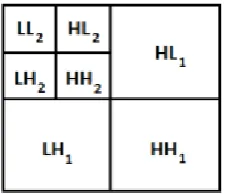
The Two-Dimensional DWT (2D-DWT) converts images from spatial domain to frequency domain. It can be accomplished by applying one-dimensional filter banks in a separable manner or using two-dimensional filter banks [5]. At each level of the wavelet decomposition, each row of an image is first transformed using a 1D vertical analysis filter-bank. The same filter-bank is then applied horizontally to each row of the filtered and sub-sampled data. One-level of wavelet decomposition produces four filtered and sub-sampled images, referred to as sub bands. The four sub bands are denoted as horizontally and vertically low pass (LL1), horizontally high pass and vertically low pass (HL1), horizontally low pass and vertically high pass (LH1), and horizontally high pass and vertically high pass (HH1). The bands other than LL generally have small values as is evident in Figure 1. Sometimes multiple levels of wavelet transform are used to concentrate data energy in the lowest sampled bands. Specifically, the LL1 sub band can be transformed again to form LL2, HL2, LH2, and HH2 sub bands, producing a two-level wavelet transform.
Fig 1: Subbands from one level of 2D-DWT.
III EMBEDDED ZEROTREE WAVELET (EZW) CODING
The EZW algorithm was introduced in the paper of Shapiro [5]. The core of the EZW compression is the exploitation of self-similarity across different scales of an image wavelet transform.
187 |
P a g e
3.1 EZW Algorithm
1.
Discrete Wavelet Transform (hierarchical subband decomposition).2.
Prediction of the absence of significant information across scales by exploiting the self-similarity inherent in images.3.
Entropy coded successive-approximation quantization. “Universal” lossless data compression which is achieved via adaptive arithmetic coding.4.
Each coefficient is assigned a significance symbols (P, N, Z, T), by comparing with the actual threshold. P (significance and positive): if the absolute value of the coefficient is higher than the threshold T and is positive.
N (significance and positive): if the absolute value of the coefficient is higher than the threshold T and is negative.
T (zerotree): if the value of the coefficient is lower than the threshold T and has only insignificant descendants.
Z (isolated zero): if the absolute value of the
coefficient is lower than the threshold T and has one or more significant descendents.
5.
The insignificant coefficients of the last sub bands, which do not accept descendents and are not themselves descendents of a zero tree, are also considered to be zero tree.IV SET PARTITIONING IN HIERARCHIAL TREES (SPIHT)
4.1 Parent and children
SPIHT is a refinement of the algorithm presented by Shapiro [8]. SPIHT assumes that the decomposition structure is the octave-band structure and then uses the fact that sub-bands at different levels but of the same orientation display similar characteristics. The different scales of the subbands imply that a region in the sub-band HL2 is spatially co-located (represent the same region in the original image) with a region 4 times larger (in the two dimensional case) in the band HL1. The parent-children relationships in two dimensions become. The diagram for parent child relation in SPIHT is shown in fig.3.
188 |
P a g e
4.2 SPIHT Algorithm
The SPIHT algorithm applies the set partitioning rules, as defined above on the subband coefficients. The algorithm is identical for both encoder and decoder and no explicit transmission of ordering information, as needed in other progressive transmission algorithms for embedded coding, are necessary. This makes the algorithm more coding efficient as compared to its predecessors. Both the encoder and decoder maintain and continuously update the following three lists, viz.
• List of Insignificant Pixels (LIP) • List of Significant Pixels (LSP) • List of Insignificant Sets (LIS)
In all lists, each entry is identified by a coordinate (n1, n2). In LIP and LSP, the entry represents individual pixels, whereas in LIS, the entry represents either set D(n1, n2) or set L(n1, n2). As an initialization step, the number (n) of magnitude refinement passes that will be necessary is determined from the maximum magnitude of the coefficients. Initially, all pixels are treated as insignificant. The initialization is followed by three major passes – the sorting pass, the magnitude refinement pass and the quantization step update pass which are iteratively repeated in this order till the least significant refinement bits are transmitted. During the sorting pass, the pixels in the LIP, which were insignificant till the previous pass, are tested and those that become significant are moved to the LSP. Similarly, the sets in LIS are examined in order for significance and those which are found to be significant are removed from the list and partitioned. The new subsets with more than one element are added to the LIS and the single pixels are added to LIP or the LSP, depending upon their significance. During the magnitude refinement pass, the pixels in the LSP are encoded for nth most significant bit. The encoding algorithm can be summarized as follows:
Step-1: Initialization:
Output n = [ Log2 (max(n1, n2 ) ({|cn1,n2 })]
Set the LSP ={Ø}
Set the LIP ={(n1,n2)ЄH} and LIS={D(n1,n2), L(n1, n2) ЄH }
Step-2: Sorting pass:
Step-2.1: For each entry in the LIP, output the significance (“1” if significant, “0” if not significant). If found significant, remove it from the LIP and add to the LSP.
Step-2.2: For each entry in the LIS, output the significance. If found significant, output its sign. Perform the set partitioning using the rule-2 or rule-3, depending upon whether it is the D(n1,n2) set or the L(n1,n2) set. According to the significance, update the LIS, LIP and LSP.
Step-3: Refinement pass:
For each entry in the LSP, except those which are added during the sorting pass with the same n, output the nth most significant bit.
Step-4: Quantization-step update pass:
189 |
P a g e
V JPEG2000
JPEG 2000 is the international standard for still images. This is the enhancement to the existing JPEG system. The JPEG 2000 implements a new way of compressing images based on the wavelet transform. This supports lossy and lossless compression of gray scale as well as color images. Here in this processes encoding and decoding process takes place.
5.1 Algorithm:
1.
The source image is decomposed into components.2.
The image and its components are decomposed into rectangular tiles. The tile-component is the basic unit of the original or reconstructed image.3.
The wavelet transform is applied on each tile. The tile is decomposed in different resolution levels.4.
These decomposition levels are made up of sub bands of coefficients that describe the frequency characteristics of local areas (rather than across the entire tile-component) of the tile component.5.
The sub bands of coefficients are quantized and collected into rectangular arrays of “code-blocks”.6.
The bit-planes of the coefficients in a “code-block” are entropy coded.7.
The encoding can be done in such a way, so that certain ROI’s can be coded in a higher quality than the background.8.
Markers are added in the bit stream to allow error resilience.9.
The code stream has a main header at the beginning that describes the original image and the various decomposition and coding styles that are used to locate, extract, decode and reconstruct the image with the desired resolution, fidelity, region of interest and other characteristics.10.
The optional file format describes the meaning of the image and its components in the context of the application.VI RESULTS AND DISCUSSIONS
The above said algorithms are simulated using MATLAB environment for various images such as Cameraman, Lena, and Medical image. The performance parameters such as compression ratio, MSE and PSNR are calculated and compared.
Compression ratio:
It is the ratio of the size of the original image to the size of the compressed image.Mean Square Error (MSE)
=
190 |
P a g e
(a) Cameraman (b) Lena (c) Medical image
Fig.4: Original images
Table 1: Comparison of different coding techniques
Image Method Compression
Ratio MSE PSNR
Cameraman
EZW 4.51 0.31 27.2
JPEG2000 4.69 0.26 29.91
SPIHT 13.85 0.22 30.03
Lena
EZW 4.60 0.28 28.67
JPEG2000 4.82 0.2 29.97
SPIHT 14.88 0.17 48.96
Medical Image
EZW 4.93 0.23 30.44
JPEG2000 5.25 0.48 24.7
SPIHT 16.11 0.13 56.95
It is very clear from the above simulation results that SPIHT performs well when compared to EZW & JPEG2000. Compression ration can be increased by reducing the number of redundant bits in the image. Different encoding techniques are compared with compression ratio, MSE, and PSNR for different images such as Cameraman, Lena, and Medical image.
VII CONCLUSION
191 |
P a g e
REFERENCES
[1].Garima Chopra and A. K. Pal “An Improved Image Compression Algorithm Using Binary Space Partition Scheme and Geometric Wavelets” IEEE transactions on image processing, vol. 20, pp.270-275, 2011. [2].M. A. Losada, G. Tohumoglu, D. Fraile, and A. Artes, “Multi-iteration wavelet zerotree coding for image
compression,” Sci. Signal Process., vol. 80, pp. 1281–1287, 2000.
[3].G. K. Wallace, “The JPEG still-picture compression standard,” Commun. ACM, vol. 34, pp. 30–44, Apr. 1991.
[4].MPEG-2video, ITU-T-Recommendation H.262-ISO/ IEC 13818-2, Jan. 1995.
[5].K. R. Rao and P. Yip, Discrete Cosine Transform: Algorithms, Advantages, Applications. New York: Academic, 1990.
[6].J. M. Shapiro, “Embedded image coding using zero trees of wavelet coefficients,” IEEE Trans. Signal Process., vol. 41, no. 12, pp. 3445–3462, Dec. 1993.
[7]. A. Said and W. A. Pearlman, “A new, fast and efficient image codec based on set portioning in hierarchical trees,” IEEE Trans. Circuits Syst.Video Technol., vol. 6, no. 3, pp. 243–250, Jun. 1996.