PASSIVE CONTROL OF FLOW STRUCTURE INTERACTION
BETWEEN A SPHERE AND FREE-SURFACE
Muammer OZGOREN1
1. I
NTRODUCTION, Sercan DOGAN2, Abdulkerim OKBAZ3, Besir SAHIN4, Huseyin AKILLI5
Abstract: Flow characteristics for both a smooth and a vented sphere such as velocity vectors, patterns of streamlines, vorticity contours, stream-wise fluctuations, cross-stream velocity fluctuations and Reynolds stress correlations between a sphere and free-surface for various submerged ratio at Re =5,000 are studied by using dye visualization and the particle image velocimetry technique. Passive control of flow structure interaction between sphere and free surface was examined by using a modified geometry which has a 15% sphere diameter hole passing through the sphere equator. Both of the spheres were separately placed beneath the free surface with different positions from touching to the free surface to two sphere diameters below the free surface. It is demonstrated that reattachment point of the separated flow to the free surface varies for both of the sphere cases as the sphere position alters vertically through the water flow while the flow structure for the vented sphere occurs considerably symmetrical due to forming of a pair of counter-rotating ring vortices.
Keywords:Free-surface, Passive control, PIV, Sphere, Turbulence, Wake flow
Fluid mechanics applications in between a free surface and sphere are encountered in the area of off-shore oil storage tanks, transporting of silicon and polymer, conveying of sediment materials in the river, spherical swimming bodies in the sea or rivers, sport balls, bombs, manned/unmanned submarine research vehicles, flow-structure interactions in aerodynamics and hydrodynamics. Result of fluid-structure interaction can cause important variations both on the bluff body and the flow structure. Therefore, there are numerous experimental, theoretical and numerical studies in the literature concerning with basic features of the flow structure around a sphere >1-20@. However, fewer studies were found about flow control using passive and active devices around a sphere given in the references and cited therein such as dimpled sphere >8-10@, sphere with o-ring [10] and vented sphere >14-17@. Some of the other related studies on the flow control concerning with the present study can be found in the literature >20-28@. Suryanarayana and Prabhu >17@conducted experiments in water and wind tunnels on
1Assoc.Prof.Dr, Mechanical Engineering Department, email: [email protected]
2Research Assistant, Mechanical Engineering Department, email: [email protected]
3 Project Assistant, Mechanical Engineering Department, email: [email protected]
4 Prof.Dr, Mechanical Engineering Department, email: [email protected]
5Prof.Dr, Mechanical Engineering Department, email: [email protected]
spheres in the Reynolds number range 6x10³ to 6.5x10⁵ to study the effect of natural ventilation on the boundary layer separation and near-wake vortex shedding characteristics. In the subcritical range of Re (<2x10⁵), ventilation caused a marginal downstream shift in the location of laminar boundary layer separation; there was only a small change in the vortex shedding frequency. In the supercritical range (Re> 4 x 10⁵), ventilation caused a downstream shift in the mean locations of boundary layer separation and reattachment; their results showed significant axisymmetry in the presence of venting.
Most recently, passive control of vortical flow structure around a sphere by an o-ring for Re=5,000 has been experimentally investigated. Visualization with Rhodamine dye and particle image velocimetry technique are performed to examine the flow characteristics such as instantaneous velocity fields, vorticity contours and time-averaged flow patterns of rms velocities in x and y directions, velocity fields and Reynolds stress correlations. O-rings with 2mm and 3mm diameters are located at the front side of the sphere having 42.5 mm diameter at angles of 450, 500, 550 and 700 to see suppression effect for dye experiment. It has been found from dye visualization and PIV results that the controlled flow structure results of the sphere with 2mm o-ring at 550 is the most effective [10]. The flow characteristics of a smooth sphere and a vent sphere located in a uniform flow for Reynolds number range 2500 particle image velocimetry technique and qualitatively with dye visualization. The flow phenomena in the downstream regions of the sphere increase the instability of the vortical flow structure significantly [13]. An experimental investigation of flow structures downstream of a circular cylinder and sphere immersed in a free-stream flow was performed for Re=5000 and 10000 using qualitative and quantitative flow visualization techniques [14]. Flow data reveal that the size of wake flow region, the location of singular and double points, the peak values of turbulence quantities, such as Reynolds stress correlations, vorticity fluctuations and turbulent kinetic energy vary as a function of models’ geometry and Reynolds Numbers. They stated that the concentration of small scale vortices is more dominant in the wake of the sphere than that of the cylinder.
The objective of the present work is to investigate the possibility of controlling flow structure in the downstream of the sphere by altering the position of the sphere from free-surface of water as well as the geometric modification in terms of a vent. In the literature, it has not been encountered any study that is related to the interaction between free-surface and sphere.
2. EXPERIMENTAL SETUP
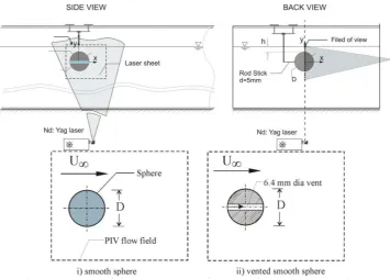
Re=5,000. The sphere with a diameter of 42.5 mm was made of plexiglass so that the laser light propagates easily from them. In addition, water cell segment of the sphere equator with a diameter of 38.5mm and a wall thickness of 2.0 mm was created. It was filled with distilled water and had a total height of 8 mm in order to reduce largely the laser light deflection on the sphere. The sphere surface was highly polished to avoid effects of surface roughness. The laser sheet was located at 225 mm above the bottom surface of the channel while the water height hw was 450 mm in all cases. The Froude
number based on the water depth hw was Fr Uf ghw=0.056, which was subcritical
flow region owing to the less than 1.0. To support the sphere in the water channel, a circular bar with a 5 mm diameter was connected to the sphere from the top. Disturbance effect of the support bar on the laser sheet location of the measurement plane that was observed by dye injection was negligible in the consideration of support diameter with respect to the sphere diameter. The solid blockage ratio of the sphere including support was 1.3%. The vented sphere made of solid plexiglass and did not permit to pass the laser light. The ratio of the smooth sphere diameter (D=42.5 mm) to vented hole diameter (dhole =6.4 mm) is dhole/D=0.15, which provides a vent area of
2.26%. For dye visualization, dye ports with 0.7mm diameter are located on the equator of the sphere at angle values with respect to the flow direction as 0o, 70o,90o, 110o, 1800, 2900, 2700 and 2500.
Figure 1:Schematic view of the experimental setup of PIV system and sphere position for a smooth and a vented sphere case
thickness in the flow field was approximately 1.5 mm. As shown in Figure 1, the camera was mounted in a fixed position beneath the water tank. Dantec Flow Grabber digital PIV software employing the cross-correlation algorithm was used to compute the raw displacement vector field from the particle image data.
3. RESULTS AND DISCUSSION
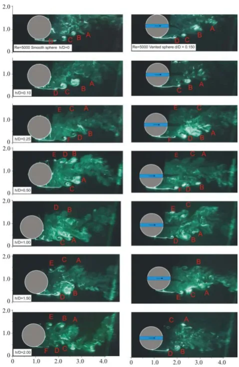
Dye visualization representative images for the smooth and vented sphere case are presented in Figure 2. As it is seen, the separated and recirculating flow in the near-wake region with the help of visualizing are clearly seen for the sphere with laser illumination using the Rhodamine dye injection technique in the near wake region. Small scale vortices around the wake region designated by A to F are formed around larger vortices with a wavy appearance due to Kelvin Helmholtz instability. Formation of the spiral vortices begins to occur in the very close region of the sphere. As the flow travels in the downstream direction, the dimensions of the vortices increase around the bluff body. Then these vortices are shed from the periphery of the sphere directly to the inward wake region. The large eddies are formed at a regular frequency, and they produce pressure disturbances in the flow. The flow patterns in Figure 2 show that the laminar boundary layer separates at around T=850±50, where T is measured from the front stagnation point. The Reynolds number Re=5000, is well below critical, so the boundary layer on the sphere is laminar. Shedding shear layer becomes unstable due to the Kelvin-Helmholtz instability caused by the large velocity difference at the interface between the free-stream and sphere wake flow regions. Thereafter, the laminar shear layer turns into a powerful turbulent flow structure. Several vortex-ring shaped protrusions appear as an indication of the shear-layer instability along the borders between the wake and free stream regions, as also observed by Jang and Lee >3@. For the cases of h/d=0 and 0.1 in Figure 2, shedding vortices from the bottom shoulder of the sphere which have high rate interactions travel in the direction of the main flow to merge with the free-surface. As it is clearly seen from the top three images in Figure 2, the wake region of the sphere with the vent is shortened in size compared with the results of the smooth sphere due to the occurring of jet flow through the vent. The jet flow exiting from the vent moves in longitudinal direction and stirs the wake flow region to increase the entrainment to a higher level as clearly seen for the right column images. As seen from dye visualization in Figure 2 and instantaneous flow patterns in Figures 3 and 4, the wake becomes increasingly unstable for the submerged depths between 0 the vortex shedding keeps its axisymmetry. The vortices become highly three-dimensional with quasi periodic shedding apparent in images taken at the equator plane of the sphere with and without vent.However, this patterns could be changed considerably for a vented sphere case.
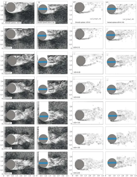
Figures 3 and 4 show comparison of instantaneous velocity fields V and Z* around the smooth sphere (left column) and vented sphere (right column) for Re=5,000. Instantaneous vorticity contours of the wake structure is normalized as Z* (i.e.,
Z*=ZD/U). All figure dimensions are normalized with the sphere diameter designated as
Figure 2: Comparison of flow visualization of flow structure with laser illumination of Rhodamine dye injection technique around the smooth sphere (left column) and vented sphere (right column) at Re=5,000.
sphere can shed at considerably different times causing small asymmetries in the wake pattern. The flow regime is unstable and restricted in downstream of the sphere around three sphere diameters region. The length of the wake region increases with increasing submerged depth of the sphere for both of the sphere cases. In addition, at higher h/D
sphere and corresponding patterns of vorticity shows that the shear layer is pushed to the base region causing a well defined concentration of vorticity as seen in all images in Figures 3 and 4. The wake region accommodates velocity vectors with very small magnitude in the downstream region of the smooth and vented sphere, which are the source of small-scale secondary vortices, as seen in Figures 3 and 4. The streamwise separation of successive vorticity peaks in the near wake region for the smooth sphere is larger than that for the vented one. The flow is three-dimensional, and shedding vortices convey fresh fluid into the wake flow region, magnifying the entrainment processes, which occurs with higher order of magnitude for the vented sphere. However, it is clear that there is only a small change on the flow patterns in the presence of ventilation for h/D!1.0. On the other hand, Suryanarayana and Prabhu [17] stated that the observed drag reduction of wake unsteadiness, presumably caused by the stabilization/weakening of the randomly rotating 3-D vortical structure of the smooth sphere, which was also observed in the present study. As seen in Figure 4, secondary vortices forms in the wake region due to jet flow through the vent. It may be noted that any reduction in the wake unsteadiness may be expected to result in drag reduction. The modified flow structure of the near wake of the vented sphere may be characterized by a pair of counter-rotating ring vortices, which have the effect of aerodynamically streamlining the sphere as expressed by Suryanarayana and Prabhu [17]. As pointed by Suryanarayana and Prabhu [17], the effect of natural ventilation can be categorized in two broad regimes as weak and strong interaction regimes. At subcritical Reynolds number (Re4x105), the weak interaction regime occurs and the broad features of the basic unvented sphere are largely unaltered despite the larger addition of mass in the near wake. Strong interaction is promoted by the closer proximity of the inner and outer shear layers at the supercritical Re, which results in a modified/weakened and steady near-wake flow characterized by reduced unsteadiness. Sheridan et. al. (1997) studied on flow past a cylinder beneath a free surface which gives rise to fundamental classes of near wake structure creating distinctly different from the wake of a completely submerged cylinder. They demonstrated that the instantaneous vorticity flux on either side of this jet is rapidly balanced immediately after the onset of separation from the free surface. The jet of fluid passing over or under the sphere exhibited a number of possible states including: attachment to the free surface; attachment to the sphere surface; and an intermediate state in between as in the experimental results of Sheridan et al.[26].
In fact, these identifiable structures of vorticity exist even at region well downstream of the free-stagnation point as seen for the cases h/D!1.0.
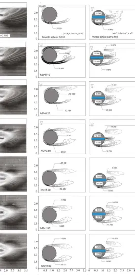
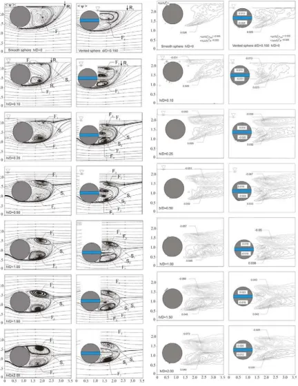
Comparison of the normalized flow patterns of the smooth sphere (left column) and the sphere with a vent (right column) for the time-averaged velocity field <V>, streamline patterns \!, time-averaged vorticity Z!(i.e., <Z*>=<ZD/U>), rms (root mean square) velocity fluctuation contours of the stream-wise velocity
u
rmsU
f!
and cross-stream velocity vrms Uf! are displayed in Figures 5-9. For these and other figs, the minimum and normalized incremental values of the patterns are given on each image.Variations of the time-averaged velocity fields <V> and vorticity contours <Z*> depending on the sphere locations beneath the water free-surface and effect of the ventilation for Re=5,000 are displayed in Figures 5 and 6. The time-averaged velocity fields <V> indicate that vortex formation occurs immediately adjacent to the base of the sphere and those shedding vortices immigrate in the direction of the free stream flow to merge by the free-surface of the water channel. It is obviously seen that near wake formation changes periodically due to the jet flow from the vent into the wake flow region. The jet flow from the vent goes along the ventilation axis and slightly changes the direction toward the free-surface by dividing the wake region for 0
Having the flow jet through the vent for the right column images in Figure 6, wake flow region of the sphere is activated. It is apparent from the instantaneous and time-averaged images that the jet flow through the vent can substantially affect the onset and development of large-scale vortical structures in the near wake region, relative to those occurring from the smooth sphere for h/D0.5. A pair of vortices for the case of the sphere with the vent is developed in the wake region due to the jet flow emanating from the vent. For h/D=2.0, two symmetric vortices rotating in opposite direction are clearly seen in both cases in Figure 6. Time-averaged positive and negative vorticity layers are approximately equal and symmetric with each other. For the sphere with the vent, flow structures are restless due to the continuous developing flow process due to the vent. Entrainment process due to the high rate of circulatory flow motion on vortical flow structure is extremely high engender energetic wake flow structure. As it is seen from time-averaged flow data for the sphere with the vent, distributions of flow patterns in the wake-flow region is shortened in size in the longitudinal direction and slightly narrowed in size lateral direction comparing with the smooth sphere.
As seen in Figure 6, time-averaged vorticity images Z!of the sphere with and without a vent reveal that the detailed instantaneous structure of the small-scale vortices and far downstream part of the Kármán vorticity street disappear completely due to the unsteady flow structure and alternating direction of the shedding vorticity from both sides of the spheres for the sphere with and without a vent cases. In the base region, two separated shear layers with oppositely signed vortices interact with each other more Flow patterns of the time-averaged stream-wise velocity fluctuations <urms/Uf> and
cross-stream velocity fluctuations <vrms/Uf> depending on the sphere locations beneath
free-surface of the water and effect of the ventilation for Re=5,000 are shown in Figures 7 and 8.
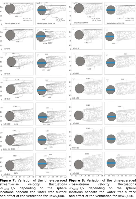
Flow patterns of the time-averaged stream-wise velocity fluctuations <urms/Uf> and
cross-stream velocity fluctuations <vrms/Uf> depending on the sphere locations beneath
Figure 3: Variation of the instantaneous velocity fields V depending on the sphere locations beneath the water free-surface and effect of the ventilation for Re=5,000.
Figure 5: Variation of the time-averaged velocity field <V> depending on the sphere locations beneath the water free-surface and effect of the ventilation for Re=5,000.
Figure 7: Variation of the time-averaged stream-wise velocity fluctuations <urms/Uf> depending on the sphere
locations beneath the water free-surface and effect of the ventilation for Re=5,000.
Figure 8: Variation of the time-averaged cross-stream velocity fluctuations <vrms/Uf> depending on the sphere
The rms stream-wise velocity fluctuations patterns <urms/Uf> have detectable double
peaks at almost equal distances in the upper and lower wake regions of the centerline for the smooth sphere whereas they have three peaks, one of them emanating from the vent, for the case of the sphere with the vent for h/D!1.0. For the contours of <vrms/Uf>, the cross-stream fluctuations are associated with the process of formation of
the large-scale vortical structures. Peak values of the cross-stream fluctuations <vrms/Uf> for the sphere with the vent depending on the submerged depth are less than
the smooth one as shown in Figure 8. In addition, the distance between the sphere base and the maximum point location for all submerged ratios h/D decreases for the sphere with the vent. For example, the maximum values of the <vrms/Uf> contours for
Re=5,000 on the centerline of the wake take place nearly at approximately 1.26D and 0.81D for the sphere without and with the vent at h/D=2.0, respectively.
The cross comparison of the results reveals double peaks for <urms/Uf> , while a single
peak is seen in <vrms/Uf> with the maximum occurrence around the axis for both of the
sphere cases.
and Lee[3], Leder and Geropp[4]). As it is seen from cross-comparison of the time-averaged velocity fields <V> and vorticity contours <Z*>, distributions of the flow patterns clearly indicate that the wake flow area for the sphere without vent is smaller than that for the sphere with the vent. h/D=0 and 0.1. Those for the sphere with the vent were found to be around 1.54D and 1.33D for h/D=0 and 0.1, respectively. For h/D=0 configuration, a primary circulating bubble or developing focus which are designated as F1 is formed and covers whole the wake flow region. For the case of h/D =0.25, the wake region with foci F1 and F2 are identifiable and then the saddle point S is formed just beneath the free-surface for the smooth sphere. Furthermore, each of these developing and primary cells has a stable focus that is the streamlines spiral towards inward the central points of foci. The length of the wake flow region in the stream-wise direction is varied as a function of h/D. The effective length of the jet flow decreases with increasing the submerged depth of the sphere. The saddle point S1 on the time-averaged streamline topology generally forms earlier for the vented sphere case. For example at h/D=2.0, the non-dimensional wake lengths (L/D) measured from the base of the sphere to the saddle point S1 in the averaged streamline topology <<> are approximately 1.21D and 1.07D for the smooth sphere and vented sphere, respectively. Here, L is the distance between the sphere base and saddle point S1. The L/D values for the sphere without the vent were respectively determined as 0.98, 1.5, 1.18 and 1.19 for the submerged depth ratios of h/D=0.25, 0.50, 1.0 and 1.50 while those for the sphere with the vent were, in sequence, 0.72, 0.98, 1.08 and 1.06. Finally, it can be interpreted that the drag force could decrease as the saddle point becomes closer to the sphere.
4. CONCLUSIONS
The sphere is placed from the free surface touching position to two sphere diameters below the free surface with different locations. Dye visualization, velocity vector fields and corresponding vorticity contours, streamline topology and velocity fluctuations were used to explain the characteristics of the flow. The obtained results summarized as follows.
Figure 9: Variation of the streamline patterns \! depending on the sphere locations beneath the water free-surface and effect of the ventilation for Re=5,000.
Figure 10: Variation of the Reynolds stress correlation <u'v'/U2>
sphere for all Reynolds numbers as shown in Figure 10. For the vented sphere case, peak values of Reynolds stress correlations are varied considerably due to the effect of the jet flow in the subcritical Reynolds number range. Therefore, surface modifications as in examined in the present study may always results effectively in all cases because there could be a need to retain the structural geometry due to design considerations as well as application of Reynolds number range. The vented sphere model could significantly suppress vortex formation by diffusing the concentrated vorticity in the shear layers behind the body for supercritical Reynolds numbers. Reynolds stress correlations becomes smaller for the smooth sphere case than the vented sphere because of the three-dimensional vortex interactions. However, the concentration of small scale vortices (eddies) is more dominant in the wake of the vented sphere than that of the without vent sphere. Peak values of the larger scale Reynolds scale concentrations generally decrease with increasing submerged ratio as seen all images except h/D=0.25 and 0.50. positive and negative small scale Reynolds Stress correlations occur at the exit region of the vent hole and their magnitudes are always less than half of the larger scale one.
In general, vortex formation lengths for the sphere with the vent are shorter than the smooth sphere case. It is found that the submersed portion of the sphere influences the instability of the vortical flow structure significantly. The shedding location of the large-scale vortices rotates slowly and irregularly, and they rotate at random about the stream-wise axis when they travel downstream for both the smooth and vented spheres. The effect of the free surface due to the present of the sphere continue until the h/D=0.50. As the distance between the free surface and the bottom shoulder of the sphere increases, the reattachment point to the free surface goes further upstream for h/D=0 and 0.1. The flow structure becomes very fluctuating and includes small scale vortices with low velocity distributions in the region between bottom point of the sphere and reattachment point until h/D!0.5. Small scale vortices due to the flow through the ventilation magnify the entrainment and circulatory motions between the core wake and free-stream flow regions downstream of the sphere with the vent. When compared to the smooth sphere case, sphere with the vent is found to be better performing as a vortex suppression device even though the Reynolds number is in the subcritical range. The main disadvantage of the vented sphere can be that the hole in the equator of the sphere weakens slightly the body and it might be more expansive from the point of manufacturing process. A small hole like 0.15% diameter of the bluff body could reduce the drag and fluctuating side forces due to vortex shedding. It is observed that the modified flow structure of the near wake of the vented sphere may be characterized by a pair of counter-rotating ring vortices, which have the effect of aerodynamically streamlining the sphere. The present results can be useful for validating numerical predictions and designers.
5. ACKNOWLEDGEMENT
6. R
EFERENCES[1] E Achenbach, Vortex shedding from spheres, J. Fluid Mech. 62(2), 1974, pp.209–221.
[2] I Hadzic, V Bakic, M Peric, V Sajn, F Kosel, Experimental and numerical studies of flow around sphere at sub-critical Reynolds number, Eng. Turbul. Model Exp. 5, 2002, pp.667–676.
[3] Y II, J Jang, S J Lee, PIV analysis of near-wake behind a sphere at a subcritical Reynolds number, Exp. Fluids. 44, 2008, Issue 6, 905-914.
[4] A Leder and D Geropp, The unsteady flow structure in the wake of the sphere, SPIE 2052, 1993, pp.119–126.
[5] T Leweke, M Provansal, D Ormie`res and R Lebescond, Vortex dynamics in the wake of a sphere, Phys. Fluid, 1999, vol.11, Issue9, p.12.
[6] S Taneda, Experimental investigation of the wake behind a sphere at low Reynolds number, J. Phys. Soc. Japan. 11, 1956, Issue.10, pp.1104–1108.
[7] K Aoki, A Ohike, K Yamaguchi, Y Nakayama, Flying Characteristics and Flow Pattern of A Sphere With Dimples, Journal of Visualization, 2003a, pp.67-76. [8] J Choi, J Woo-Pyung and H Choi, Mechanism of Drag Reduction by Dimples on a
Sphere, Physics of Fluids 18, 2006, 041702.
[9] J Jeon, J Choi, J Woo-Pyung, C Haecheon and ^__P, Active control of flow over a sphere for Drag Reduction at a Subcritical Reynolds number, J. Fluid Mech. vol.517, 2004, pp.113–129.
[10] M Ozgoren, A Okbaz, S Dogan, A Kahraman, R Hassanzadeh, B Sahin and H Akilli, Passive Control of Vortical Flow Structure around a Sphere by an O-ring, Ela{_|thInternational Advanced Technologies Symposium, 2011, ETE-53. [11] M Ozgoren, B } E ~_ and X$__ H, Experimental Investigation of Flow
structure around a Sphere and Cylinder via Flow Visualization, 5. Ankara International Aerospace Conference, Ankara, 17-19 August 2009, AIAC-2009-012.
[12] M Ozgoren, ? } ~_ X$__ Comparison of flow structure around sphere and cylinder, 17th National Thermal Science and Technology Conference, Sivas-Turkey, Haziran 2009, pp.73-79, 24-27.
[13] M Ozgoren, A Okbaz, A Kahraman, R Hassanzadeh , B Sahin, H Akilli, S Dogan: Experimental Investigation of the Flow Structure around a Sphere and Its
!! ^ ! ~ {_ |th International Advanced Technologies
Symposium, 2011, ETE-50.
[14] M Ozgoren, E Pinar, B Sahin, H Akilli, Comparison of flow structures in the downstream region of a cylinder and sphere, Int. J. Heat Fluid Flow, 2011, doi:10.1016/j.ijheatfluidflow.
[15] G K Suryanarayana, H Pauer and GEA Meier, Bluff-body drag reduction by passive ventilation, Exp. Fluids 16, 1993, 73-81.
[16] G K Suryanarayana, GEA Meier, Effect of ventilation on the flow field around a sphere, Exp Fluids 19, 1995, pp.78-88.
[17] G K Suryanarayana and A Prabhu, Effect of natural ventilation on the boundary layer separation and near-wake vortex shedding characteristics of a sphere, Exp. Fluids 29, Issue.7, 2000, pp.582–591.
[19] Kim D Yung and H Choi, Vortical structures behind a sphere at subcritical Reynolds numbers, Phys Fluids 18(1):015102, 2006, doi:10.1063/1.2166454. [20] S Jeon and H Choi, Suboptimal Feedback Control for Drag Reduction in Flow
over a Sphere, Bull. Am. Pbys. Soc., 2005, 50:56.
[21] M M Zdravkovich, Review and classification of various aerodynamic and hydrodynamic means for suppressing vortex shedding, J. Wind Eng Ind. Aerodyn, 7, 1981, pp.145-189.
[22] C Haecheon, J Woo-Pyung and K Jinsung, Control of Flow Over a Bluff Body, Annu. Rev. Fluid Mech., 40, 2008, pp.113–39.
[23] M Gad-el-Hak, Modern Developments in Flow Control, Applied Mechanics Review, vol, V. 49, 1996, pp.365-379.
[24] P Bearman and M Brankovi´c, Experimental studies of passive control of vortex-induced vibration, European Journal of Mechanics B/Fluids 23, 2004, 9–15. [25] J C Owen and P W Bearman, Passive control of VIV with drag reduction, Journal
of Fluids and Structures 15, 2001, pp.597-605.
[26] J Sheridan, J C Lin, D Rockwell, Flow past a cylinder close to a free surface, J. Fluid Mech. 330, 1997, pp.1–30.
[27] T Igarashi, Flow characteristics of a circular cylinder with a vent, Bulletin of the JSME 21, 154, 1978, 656-664.