Abstract—MIMO systems have become an essential part in many communications networks and Long Term Evolution (4G) mobile communication systems. Mobile handsets using lower band of LTE (LTE-700 band) require antennas of reduced size that can be adapted to the limited space in the handset. This paper presents the design, optimization and implementation of two meandered-line PIFA antennas working as an MIMO system with high isolation for LTE-700 band mobile applications. To solve the problem of mutual coupling, a combination of decoupling arrangements was used to improve the isolation between the two antennas. The influences of various design parameters are investigated using the CST Microwave Studio Suite. A prototype of the proposed Meandered-line PIFA Antenna was fabricated and tested using vector network analyzer. Good agreement was found between the simulated and measured results. The fabricated MIMO antenna shows an isolation better than 12 dB and a −6 dB bandwidth of (75 MHz) in the frequency range from (720 MHz) to (795 MHz). The antenna has 1.94 dB gain, total efficiency of 85%, and volume of 110×65×1.6 mm3, that is (0.275×0.1625×0.004) in wavelengths.
1. INTRODUCTION
The Long-Term Evolution (LTE) is a broadband solution that offers various features with good flexibility in terms of deployment options and potentials for mobile services [1]. Recent wireless communication systems require higher data rates to support the increasing mobile services [2]. An MIMO system can increase the channel capacity and improves reliability without sacrificing spectrum efficiency or consuming additional transmitted power [3]. MIMO systems constructively explore multi-path propagation using different transmission paths to the receiver to improve wireless systems capacity, range and reliability [3]. Various designs of MIMO antennas have been reported for the mobile handset using PIFA and monopole configurations [4–8].
In an MIMO antenna system, high antenna coupling results from signal leakage from one antenna to another leading to reduced antenna efficiency due to the power absorbed by a close element with strong coupling. The problem is magnified in the portable wireless devices where the MIMO antennas are placed very close due to the limited space. Therefore, the reduction of coupling is a major consideration in MIMO antenna design to reduce the correlation between the multiple elements.
Significant research efforts have been reported to reduce the mutual coupling [6–13]. A T-shape slot impedance transformer added to both single and dual band PIFA’s resulted in an isolation better than 20 dB [6]. In [7] an additional non-radiating folded shorting strip connected between the antenna element and ground plane resulted in an isolation better than 28 dB for the lower WLAN band. In [8], two quarter-wavelength slots in the ground plane were used to reduce the coupling. Slits were also introduced in the ground plane to reduce mutual coupling and enhance isolation of the MIMO antenna [9]. Insertion
Received 20 June 2016, Accepted 26 August 2016, Scheduled 24 September 2016
* Corresponding author: Khalil Hassan Sayidmarie ([email protected]).
of a neutralization line between the two antenna elements is a promising method that has been used in [10, 11].
A decoupling network consisting of two sections of a transmission line is placed at the center of the two antenna elements in an LTE MIMO system is recently proposed [12]. The isolation was enhanced by approximately 23 dB comparing to that without a decoupling network. The fabricated MIMO antenna satisfied a 6-dB return loss requirement and the envelope correlation coefficient is maintained below 0.4 over the LTE band 13 ranging from 746 to 787 MHz [12]. A decoupling element for enhancing the port isolation in MIMO antennas for triple (LTE) bands was presented in [13]. A spiral decoupling structure is added between two strongly coupled antennas to enhance the port isolation by 20 dB [13]. In [14] a fork-shaped structure was introduced in the ground plane to decrease the mutual coupling between the antennas. The obtained simulation results show a high isolation of about 20 dB. The reduction of antenna coupling in MIMO systems becomes a challenging problem at the lower band of the LTE since the allowable separation is a very small fraction of the wavelength.
In this paper, an MIMO meandered-line PIFA antenna is proposed for LTE-700 MHz band applications. The meandered-line can collect longer electrical length in a given physical area and thus helps to reduce the size of the antenna. This feature is desired since the antenna operates at low frequencies of the LTE Band 13. By combining the meandered-line with the PIFA structure, their desired properties are integrated. A combination of decoupling arrangements are investigated to improve the isolation between the two antennas. The parameters of the isolation techniques were optimized by using Particle Swarm Optimization (PSO) and Nelder-Mead optimization techniques for further improvement of the performance. These techniques are built in the CST Microwave Studio Suite which was used to analyze and optimize the proposed antenna. The proposed MIMO antennas configuration is compact and can be fitted in conventional mobile handsets.
2. DESIGN AND SIMULATION OF MIMO MEANDERED-LINE PIFA ANTENNAS
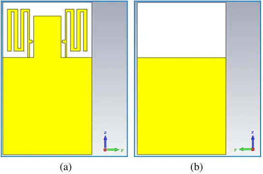
The proposed design consists of two meandered-line PIFA antennas configuration using the same substrate as shown in Fig. 1. Each antenna is based on the recently published antenna design [15]. The antenna combines a meandered-line which is known in its compact features and PIFA configuration to achieve the desired features. The antenna shape was optimized to achieve a bandwidth of (58) MHz centered at (765) MHz and VSWR of (1.04). The antenna has a compact volume of (65×110×1.6) mm3 that is a (0.165×0.28×0.004 wavelength at the center frequency of the lower band). This antenna was considered as a primary antenna for the MIMO antenna system proposed in this paper.
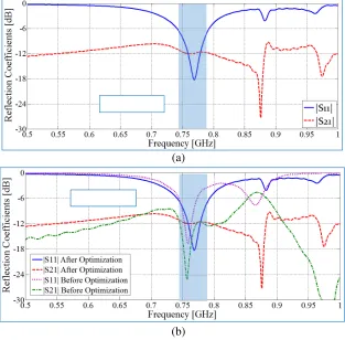
Figure 2 presents the simulation results of the MIMO configuration, which shows a lower band
(a) (b)
Figure 2. Variation of the reflection and coupling coefficients with frequency for the antennas in Fig. 1.
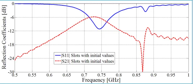
Figure 3. Reflection and coupling coefficients of the antennas when only slots were used.
around 760 MHz having a −6 dB bandwidth of (52) MHz. There is a second band across the range (1.9–2.52) GHz. The mutual coupling between the two antennas is relatively high at about (−6 dB). Hence, there is a need to implement some decoupling arrangements that can decouple the two antennas to improve the ports isolation and meet the design criteria.
3. ISOLATION ENHANCEMENT OF THE PROPOSED MIMO SYSTEM
The decoupling arrangement used in this paper is a combination of the following techniques in an attempt to integrate their desired features:
• Slot technique.
• Neutralization line technique.
• Fork-shaped structure in the ground plane.
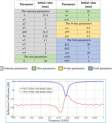
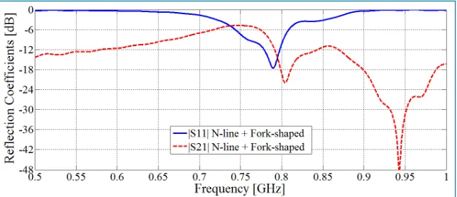
Figures 3 through 8 show the effect of each of the used decoupling techniques on the performance of the MIMO antennas, where all the simulation results were obtained with the initial parameters values (see Table 1). It can be seen from Figs. 3 through 5 that using the neutralization line technique is the most effective compared to the slots and fork-shaped line techniques in the reduction of mutual coupling. Merging of the two techniques was also introduced (see Figs. 6 to 8). However, the results of combining any two configurations were not better than that of the neutralization line technique.
Table 1. Initial values of the MIMO antenna parameters.
25
a 32.4 ws 1
g1 2 ws1 1
g2 2
g3 3 wn 0.5
26.5 0.5
ha 5.25 4.5
w1 1.1
w2 2 30
w3 2 7
w4 2 20
1
ls 30 2
The antenna parameters
Parameter Initial value Parameter [mm]
Initial value [mm]
The slot parameters
The fork parameters The N-line parameters
gap
ls1
gnh
gnv
lfo1 lfo2 wfo wfoh wfov
Antenna parameters Slot parameters N-line parameters Fork parameters
Figure 4. Reflection and coupling coefficients of the antennas when only N-line was used.
Figure 6. Reflection and coupling coefficients of the antennas when both slots and N-line were used.
Figure 7. Reflection and coupling coefficients of the antennas when both slots and fork-shaped line were used.
Figure 8. Reflection and coupling coefficients of the antennas when both N-line and fork-shaped line were used.
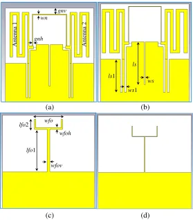
Antenna 1 ws ws1 wn ls ls1 gnh gnv lfo1 lfo2 wfo wfoh wfov (a) (b) (c) (d) Antenna 2
Figure 9. Two meandered-line PIFA antennas, (a) and (b) are the initial and the optimized antenna (top layer) respectively, (c) and (d) represent the initial and the optimized ground (bottom layer) respectively. Dimensions are given in Table 2.
Table 2. Initial and optimized values of the parameters of the MIMO Meandered-Line PIFA of Fig. 10.
25 24
32.4 31.7 1 0.6
2 2 1 1.4
2 2
3 3 0.5 0.3
26.5 27.5 0.5 0
5.25 5.2 4.5 1.7
1.1 1.6
2 2.25 30 25
2 3 7 7.4
2 2.5 20 18.5
1 0.3
30 31 2 0.6
The antenna parameters
Parameter Value (mm)
The slot parameters
The fork-shaped parameters The neutralization-line parameters
Parameter Value (mm)
inital optimized inital optimized
Antenna parameters Slot parameters N-line parameters Fork parameters
(a) (b) (c) (d)
Figure 10. Parameters of the final PIFA structure; (a) antenna parameters, (b) slot parameters, (c) neutralization-line parameters and (d) fork-shaped line parameters. Dimensions are given in Table 2.
(a)
(b)
The calculated envelope correlation coefficient between the antennas is less than (0.15) over the band (741–793) MHz and its minimum value is (0.002) at the frequency (773.5) MHz, as shown in Fig. 12 which meets the required specification of (ECC<0.5).
Figure 13 shows the current distribution on the radiating elements and the deployed decoupling structures namely; slots, N-line and the fork-shaped line. It can be seen that when one antenna element is excited the current density on the other one is small confirming the reduced coupling between the two antenna elements of the MIMO arrangements.
The gain and total efficiency were calculated and shown in Fig. 14. The total efficiency shows peaking around the frequency of 770 MHz and its value is about (65% to 85%) over the band (741– 793) MHz while the gain is about (1.88–1.94) dB over the same band.
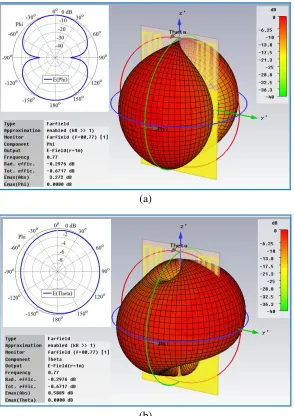
Figure 15 shows details of the radiation pattern of antenna 1. The other antenna (antenna 2) shows similar patterns. Fig. 15(a) illustrates the 3D variation of the Eφ component of the electric field. The pattern has a broad beam with a maximum in the perpendicular direction to the antenna plane. The Eφ field component vanishes along a narrow angle in the direction along the Y Z-Plane. The insert plot shows a −30 dB null along the Y-direction. Fig. 15(b) shows the Eθ component of the electric field. The pattern is omni-directional in the plane normal to the antenna. The insert plot shows that there is only 1.25 dB variation of the field in the XY-Plane. This is a desired property for mobile handset applications. It can be noticed that the maximum value of theEφcomponent is larger than the maximum value of the Eθ component by 2.7 dB indicating a relatively high cross polarized component.
Figure 12. Correlation coefficient of antennas in Fig. 9(b).
(a) (b)
Figure 14. The gain and the total efficiency of antennas in Fig. 9(b).
(a)
(b)
5. EXPERIMENTAL RESULTS OF MIMO ANTENNAS WITH DECOUPLING ARRANGEMENTS
The designed MIMO antennas with the decoupling arrangements were fabricated and tested at the Industrial Research and Development Administration at the Ministry of Science and Technology/Baghdad, see Fig. 16. The antenna was fabricated using an FR4 substrate of relative permittivity 4.3. The overall dimensions of the MIMO antenna system is 110×65×1.6 mm3.
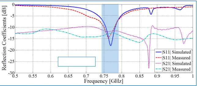
The performance of the MIMO antenna was measured using a vector network analyzer and the obtained results are compared with the simulation results as shown in Fig. 17. The figure shows that the −6 dB bandwidth of the simulation results is (52 MHz) for the band (741–793) MHz while for the measured results, it is (75 MHz) for the band (720–795) MHz. The maximum simulated mutual coupling at this band is (−11 dB), while the measured mutual coupling at this band is slightly better at the level of (−12.5 dB).
Figure 16. Prototype of the two meandered line PIFA antennas.
Figure 17. The simulated and the measured reflection and coupling coefficients of the MIMO antennas of Fig. 9.
6. COMPARISON WITH PUBLISHED WORK
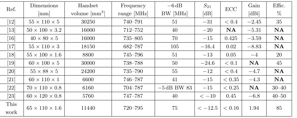
[20] 55×88×5 24200 735–790 55 −12 <0.4 −4.7 NA
[21] 60×110×1 6600 746–787 41 −15 <0.35 −4.3 NA
[22] 70×110×0.8 6160 704–787 −5 dB BW 83 −15 <0.25 NA 30–40
[23] 60×120×0.8 5760 747–787 40 <−10 0.45 −6.8 40–50
This
work 65×110×1.6 11440 720–795 75 <−12.5 <0.16 1.94 85
The bandwidth of the proposed MIMO Meandered-Line PIFA antenna is much better than most of the reported MIMO antennas. The proposed MIMO antenna has coupling value that is slightly better than those reported in [20 and 23] while the envelope correlation coefficient is better than those reported in [12, 16, 20–22 and 23]. The gain and the radiated efficiency are the best among all the ten reported works that are listed in Table 3.
7. CONCLUSIONS
An MIMO Meandered-Line PIFA antenna with decoupling arrangements for LTE-700 band has been presented. The achieved bandwidth of the proposed antenna has covered the frequency range (741– 793 MHz). The isolation between the two antennas was enhanced using the proposed decoupling arrangements by about 6 dB. The MIMO Meandered-Line PIFA antenna was fabricated using an FR4 substrate of relative permittivity 4.3. Good agreement was found between the measured and simulated results. The antenna has 1.94 dB gain, total efficiency of 85%, and volume of 110×65×1.6 mm3 that is (0.275×0.1625×0.004) in wavelengths. The proposed MIMO antenna system is suitable for commercial mobile phone applications.
ACKNOWLEDGMENT
Appreciation is due to the staff of the Industrial Research and Development Administration at the Ministry of Science and Technology/Baghdad-Iraq especially to Ghalib N. Raddad, Mahmood R. Muhsen, Rafil H. Hussain and the staff of Chemical Processing Lab. especially Ali K. Hamzah, Abdul-Ameer M. Mashkor and Naser A. Homadi for the technical support and providing the facilities to fabricate the prototype antenna, and a special thanks to Bilal Alhashimy for providing measuring facilities.
REFERENCES
1. Ali-Yahiya, T.,Understanding LTE and Its Performance, Springer Science + Business Media, LLC, 2011.
2. White paper, LTE, “The future of mobile broadband technology,” Verizon Wireless, 2009.
3. Plevel, S., et al., “MIMO: Wireless communications,” Encyclopedia of Wireless and Mobile
4. Loutridis, A., M. John, and M. J. Ammann, “Dual band LTE planar inverted-F antenna for M2M applications,” Microwave and Optical Technology Letters, Vol. 55, No. 12, 2925–2929, 2013. 5. Kearney, D., M. John, and M. J. Ammann, “Miniature ceramic PIFA for UWB band group 3 &
6,”IEEE Antennas and Wireless Propagation Letters, Vol. 9, 28–31, Jan. 2010.
6. Zhang, S., et al., “Mutual coupling reduction of two PIFAs with a T-shape slot impedance transformer for MIMO mobile terminals,” IEEE Transactions on Antennas and Propagation, Vol. 60, 1521–1531, 2012.
7. Singh, H. S., B. R. Meruva, G. K. Pandey, P. K. Bharti, and M. K. Meshram, “Low mutual coupling between MIMO antennas by using two folded shorting strips,” Progress In Electromagnetics
Research B, Vol. 53, 205–221, 2013.
8. Zuo, S., Y.-Z. Yin, W.-J. Wu, Z.-Y. Zhang, and J. Ma, “Investigations of reduction of mutual coupling between two planar monopoles using twoλ/4 slots,”Progress In Electromagnetics Research
Letters, Vol. 19, 9–18, 2010.
9. Li, J. F., Q. X. Chu, and T. G. Huang, “A compact wideband MIMO antenna with two novel bent slits,”IEEE Transactions on Antennas and Propagation, Vol. 60, 482–489, 2012.
10. Marzudi, W. N. N. W., et al., “Mutual coupling reduction of two elements antenna for wireless applications,” Proceeding: 2nd International Conference on Technological Advances in Electrical,
Electronics and Computer Engineering (TAEECE2014), Kuala Lumpur, Malaysia, Mar. 2014.
11. Su, S. W., C. T. Lee, and F. S. Chang, “Printed MIMO antenna system using neutralization-line technique for wireless USB-Dongle applications,”IEEE Transactions on Antennas and Propagation, Vol. 60, No. 2, Feb. 2012.
12. Baek, J. and J. Choi, “The design of an LTE/MIMO antenna with high isolation using a decoupling network,” Microwave and Optical Technology Letters, Vol. 56, No. 9, 2187–2191, Sep. 2014. 13. Chou, J., et al., “A novel LTE MIMO antenna with decoupling element for mobile phone
application,”EMC’14 Conference, 697–700, Tokyo, May 2014.
14. Kumar, V. and A. Pawaria, “A compact two element UWB MIMO antenna,”International Journal
of Innovative Research in Electrical, Electronics, Instrumentation and Control Engineering, Vol. 3,
No. 5, May 2015.
15. Naser, A. A., K. H. Sayidmarie, and J. S. Aziz, “A meandered line-PIFA antenna for LTE (Band-Class-13) handset applications,” Loughborough Antennas & Propagation Conference (LAPC), Nov. 2015.
16. Park, G., et al., “The compact quad-band mobile handset antenna for the LTE700 MIMO Application,”IEEE APSURSI’09, 1–4, Jun. 1–5, 2009.
17. Lee, J., et al., “Miniature Long-Term Evolution (LTE) MIMO ferrite antenna,” IEEE Antennas
and Wireless Propagation Letters, Vol. 10, 603–606, 2011.
18. Zhao, X., Y. Lee, and J. Choi, “Design of a compact planar MIMO antenna for LTE mobile application,”Proceedings of ISAP2012, Nagoya, Japan, 2012.
19. Meshram, M. K., et al., “A novel quad-band diversity antenna for LTE and Wi-Fi applications with high isolation,” IEEE Transactions on Antennas and Propagation, Vol. 60, No. 9, Sep. 2012. 20. Zhao, X., Y. Lee, and J. Choi, “Design of a compact MIMO antenna using coupled feed for LTE mobile applications,”International Journal of Antennas and Propagation, Vol. 2013, 8 pages, Article ID 837643, 2013.
21. Mun, B., et al., “New configuration of handset MIMO antenna for LTE700 band applications,”
International Journal of Antennas and Propagation, Vol. 2013, 6 pages, Article ID 850489, 2013.
22. Sun, Q., et al., “Broadband two-element array with hybrid decoupling structures for multimode mobile terminals,”IEEE Antennas and Wireless Propagation Letters, Vol. 14, 2015.