Portable Applications
Muhammad I. Magray1, *, Gulur S. Karthikeya2, Khalid Muzaffar1, and Shiban K. Koul2
Abstract—An electrically small Asymmetric Co-planar Strip (ACS)-fed MIMO antenna for USB wireless applications is proposed. MIMO antenna consists of two electrically small antennas inserted inside a 3D-printed USB prototype. Electrically small ACS-fed antenna consists of an F-shaped monopole radiator with a U-shaped slot inserted into it. The proposed antenna is compact with dimensions 11×20×0.508 mm3. The proposed MIMO antenna has dual bands which caters to WiMAX-3.5/5.5 GHz, WLAN-5.8 GHz, and C-band-6.3 GHz. The proposed architecture attains reasonable gain for the available aperture. Also, ACS-fed antenna achieves fractional bandwidth of 22% and 20% in the lower and upper bands respectively complying with the theoretical bandwidth as defined by Chu’s limit. Isolation between the radiators is greater than 15 dB in both the operating bands. Radiation patterns have high integrity, and actual USB deployment is presented. Simulation and measurement results are presented.
1. INTRODUCTION
Due to explosion in consumer electronics with multiple architecture protocols, there is a need for radiating elements with minimal physical footprint catering to operational bands [1]. Various commercial wireless standards exist across the spectrum in sub 6 GHz bands [2], for instance, Worldwide Interoperability for Microwave Access (WiMAX), Wireless Local Area Network (WLAN), and C-band applications. Multi-carrier hardware ecosystems have been designed and developed for portable devices targeting consumer applications [3] such as wireless dongles, Internet of Things (IOT) sensors, and nodes in wireless sensor networks.
The design constraints for the afore-mentioned applications are critical. These low power devices require compact radiators which snugly fit in the devices. The real-estate available in the portable device is minimal. In order to integrate the RF transceiver chain, digital processors, and other operational circuitry, the antennas must be highly miniaturized [4]. The antennas must be compliant with substrates of the RF boards used in the primary module, and it must also offer pattern diversity for enhancing throughput of the device. Antennas with specific resonances are preferred to non-resonant ultra-wideband (UWB) antennas [5]. The UWB antennas suffer from spurious radiation from closely spaced adjacent channels.
Multiple-Input Multiple-Output (MIMO) aids in enhancement of data throughput due to multipath effects [6]. Integration of the antenna module corresponding to a MIMO design in handheld portable devices is much more challenging than single element integration with motherboard. It must also be observed that patterns must be significantly distinct with low isolation which becomes challenging for design at low frequency with spatially and electrically closed environment [7].
Received 10 July 2019, Accepted 16 August 2019, Scheduled 3 September 2019
* Corresponding author: Muhammad Idrees Magray ([email protected]).
one of the popular choices for miniaturization with planar topology. Several designs have been reported such as [12, 13], but they are electrically large with the compromise in gain. Also, a few designs have been demonstrated for ACS-fed antennas with a MIMO module [14–16]. However, post integration study with actual dongle prototype is missing. Hence, an electrically small ACS-fed antenna operating in three commercial bands, WLAN, WiMAX, and C-band compliant with bandwidth specifications is proposed in this paper. Furthermore, a pattern diversity module with a low loss 3D-printed housing is investigated in this paper.
2. ACS-FED FLIPPED MIMO ANTENNA DESIGN 2.1. Single Element F-Shaped ACS-Fed Monopole Antenna
For the miniaturization of antenna, several techniques have been investigated in [17–19], but they tend to decrease the antenna efficiency. ACS feeding technique is one of the optimal methods for miniaturization. Achieving multiband in this type of feeding is relatively less challenging as tuning of the antenna has less effect on impedance matching.
Antenna simulations are carried out using computer simulation software (CST) microwave studio (MWS). All the full-wave simulations are done by modeling SMA connector of proper size. The antenna is designed on a 20 mil thick GML 1000 substrate with dielectric constant εr) of 3.2 and loss tangent
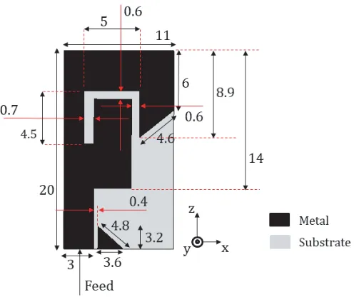
of 0.004. Schematics of the proposed F-shaped ACS-fed antenna is depicted in Fig. 1. In order to minimize various surface wave modes, a low dielectric constant substrate is chosen. In addition to this, low radiation efficiency is also the consequence of using substrate of high dielectric constant [20]. An electrically thin substrate is chosen in order to decrease cross-polarization. The proposed antenna is fed by 50 Ω characteristic impedance ACS feedline having trace width of 3 mm and gap of 0.4 mm between signal trace and coplanar ground plane. The antenna is electrically small having dimensions of 0.12λ0×0.21λ0×0.005λ0.
Figure 2. Geometry of the antennas involved in design evolution process.
The design evolution of the proposed antenna is illustrated in Fig. 2. High impedance bandwidth is obtained in UWB antennas due to deployment of tapered changing structures. Thus, first antenna A as depicted in Fig. 2 is designed which involves stepped structures for better impedance matching and broadband impedance bandwidth. A beveled ground plane is used which also improves impedance matching with larger bandwidth. Input reflection coefficient of the antenna produces strong resonance around 4 GHz.
A U-shaped ended slot is introduced in order to achieve band rejection. Length of the open-ended slot determines the notching frequency. Rejected resonance occurs at 4.5 GHz, and the length of U-shaped slot is L =L1+L2+L3 = 4.5 + 5 + 4 = 13.5 mm which is about quarter wavelength (λe)
at the notched frequency. Radiator is beveled at the upper end which also enhances the impedance bandwidth. By introducing an open-ended slot, two frequency passbands are generated which cover the 3.5/5.5 GHz-WiMAX band, 5.8 GHz WLAN band, and 6.3 GHz C-band.
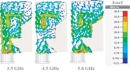
Further understanding and analyzing the working of proposed antenna is done by characterizing surface current distributions which is illustrated in Fig. 3. At notched frequency band centered at 4.5 GHz, surface currents are mainly concentrated at the U-shaped open-ended slot. The currents run opposite in direction over the U-shaped slot causing destructive interference and thus result in band notch. At passband frequencies 3.5 and 5.8 GHz, there is uniform distribution of surface currents as seen from Fig. 3.
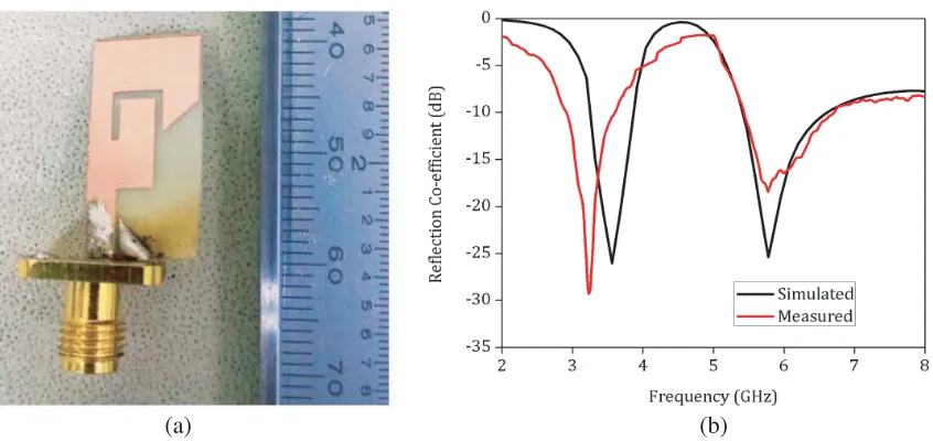
The proposed prototype is fabricated, and a photograph is illustrated in Fig. 4(a). Measured results are obtained using Agilent PNA E8364C. Simulated and measured input reflection coefficients
(a) (b)
Figure 4. (a) Photograph and (b) input reflection co-efficient of the proposed fabricated prototype.
of the proposed ACS-fed monopole antenna are depicted in Fig. 4(b). The proposed antenna has dual-band covering frequency dual-bands, 2.9–3.6 GHz and 5.4–6.6 GHz. Measured fractional dual-bandwidths of the proposed antenna are 22% and 20% in lower and upper bands, respectively. The proposed antenna covers 3.5/5.5-GHz WiMAX band, 5.8-GHz WLAN band, and 6.3-GHz C-band. Discrepancies between the simulated and measured data may be due to fabrication tolerances. Frequency shift can be observed between simulated and measured results which may be due to inhomogeneous dielectric constant of the substrate [21].
For electrically small antennas, it is better to compare measured fractional bandwidth with the theoretical limit. Relation between minimum radiation quality factor, Qmin, and size of the antenna as
first examined by Chu [22] and later formulated by McLean [23] for linear polarized antennas is:
Qmin=
1
ka+
1
(ka)3 (1)
where k = 2π/λ is the free space wave number, and a is the minimum radius enclosing maximum dimension of antenna. Yaghjian and Best [24] derived the relationship between bandwidth, B, and
Qmin:
B = 1/Qmin
s−1
√
s
(2)
wheres is the maximum allowable Voltage Standing Wave Ratio (VSWR) of antenna.
For antennas having small ground plane, sphere should enclose the entire ground plane as well as the main radiator [25]. Thus, for the proposed antenna, a is 11.41 mm, and k is 73.32 rad/m at the center frequency of the lowest operating band. Hence, ka = 0.83 <1, and thus the proposed antenna is electrically small by definition. As maximum allowable VSWR = 2 and using Equations (1) and (2), the maximum allowable theoretical bandwidth is 24.3% which is 1.1 times greater than practical impedance bandwidth of 22%. Thus, the proposed antenna is compliant to constraints of electrically small antennas.
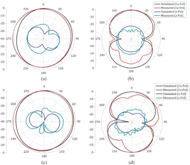
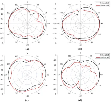
The simulated and measured radiation patterns in both the principal planes of the proposed antenna are depicted in Fig. 5 at frequencies 3.5 and 5.8 GHz. The proposed antenna achieves omnidirectional radiation patterns in XY-plane (H-plane) at both the frequencies. Simulated and measured cross-polarizations for the proposed antenna in both the planes are less than−20 dB indicating strong linearly polarized antenna. Disparity between simulated and measured results is due to poor absorptivity of oblique incidence inside an anechoic chamber. Also, deviation between the simulated and measured
(a) (b)
(c) (d)
Figure 5. Simulated and measured radiation patterns of the proposed antenna at: 3.5 GHz, (a) XY -plane, (b)Y Z-plane and 5.8 GHz, (c)XY-plane, (d)Y Z-plane.
the strayed current flowing along the exterior of the connector and cable as well as the common mode current induced along the ACS line.
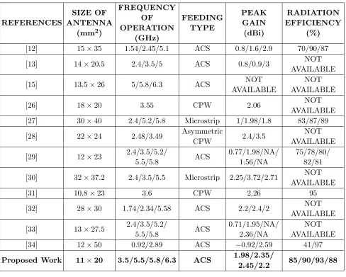
3D-radiation patterns of the proposed antenna are shown in Figs. 6(a) and (b) at frequencies 3.5 and 5.8 GHz, respectively. It provides an insight about the monopole behavior of proposed antenna. Also, gain and radiation efficiency of the proposed antenna are depicted in Fig. 6(c). The proposed antenna attains reasonable gain between 1.95 and 2.45 dBi for the available aperture in the operating range of frequencies. It is evident from Table 1 that the proposed architecture is compact and yields high gain with the available aperture.
2.2. F-Shaped ACS-Fed Flipped MIMO Antenna
The single element ACS-fed antenna proposed in Subsection 2.1 is used for ACS-fed MIMO antenna configuration. The proposed single element antenna is transformed from horizontal to vertical orientation, and the other element is flipped and kept at a proper distance so that the proposed MIMO antenna configuration is compliant to USB dongle dimensions [35]. The proposed MIMO antenna has the dimensions of 20×20×11 mm3 meeting the practical dimensions of USB module. Two elements of the proposed MIMO antenna are kept at the ends of USB Dongle as illustrated in Fig. 7.
(a)
(b)
(c)
Figure 6. 3D-radiation plots at (a) 3.5 GHz, (b) 5.8 GHz, and (c) gain and radiation efficiency plot of the proposed antenna.
Figure 7. Schematics of the proposed ACS-fed MIMO antenna inserted inside USB dongle.
to each other separated by a distance of 0.2λ0 at the lowest operating frequency of 3 GHz. Separation
is optimized in such a way that isolation between antenna elements is greater than 15 dB as shown in Fig. 9(b).
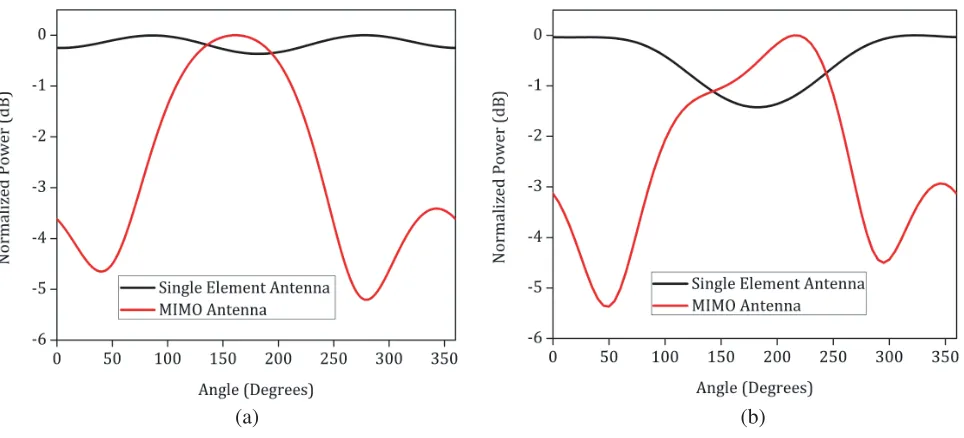
The proposed MIMO antenna exhibits stable radiation patterns achieving pattern diversity inXZ -plane as illustrated in Fig. 10. Beam tilt is observed due to the electrical offset of antennas with respect to the phase center. Discrepancies between simulated and measured radiation patterns are due to poor absorptivity of oblique incidence inside the anechoic chamber. Deviation between the simulated and measured results might also be due to the unwanted radiation produced by cable connecting SMA connector and coaxial cable. The proposed antenna achieves gain of 3.3/3.5/3.9/3 dBi at frequencies 3.5/5.5/5.8/6.3 GHz respectively as depicted in Fig. 11(a). Increase in gain is due to electrically close (0.2λ0) antenna element which acts as a reflector thus reducing the beamwidth.
(GHz)
[12] 15×35 1.54/2.45/5.1 ACS 0.8/1.6/2.9 70/90/87
[13] 14×20.5 2.4/3.5/5 ACS 0.8/0.9/3 NOT
AVAILABLE
[15] 13.5×26 5/5.8/6.3 ACS NOT
AVAILABLE
NOT AVAILABLE
[26] 18×20 3.55 CPW 2.06 NOT
AVAILABLE
[27] 30×40 2.4/5.2/5.8 Microstrip 1/1.98/1.8 83/87/89
[28] 22×24 2.48/3.49 Asymmetric
CPW 2.4/3.5
NOT AVAILABLE
[29] 12×23 2.4/3.5/5.2/
5.5/5.8 ACS
0.77/1.98/NA/ 1.56/NA
75/78/80/ 82/81
[30] 32×37.2 2.4/3.5/5.5 Microstrip 2.25/3.72/2.71 NOT
AVAILABLE
[31] 10.8×23 3.6 CPW 2.26 95
[32] 28×30 1.74/2.34/5.58 ACS 2.2/2.4/2 NOT
AVAILABLE
[33] 13×27.5 2.4/3.5/5.2/
5.5/5.8 ACS
0.71/1.95/NA/ 2.36/NA
NOT AVAILABLE
[34] 12×50 0.92/2.89 ACS −0.92/2.59 41/97
Proposed Work 11×20 3.5/5.5/5.8/6.3 ACS 1.98/2.35/
2.45/2.2 85/90/93/88
(a) (b)
(a) (b)
Figure 9. (a) Input reflection co-efficient and (b) isolation of proposed antenna.
(a) (b)
(c) (d)
(a) (b)
Figure 11. (a) Gain and Radiation efficiency. (b) ECC and diversity gain of the proposed ACS-fed MIMO antenna.
(a) (b)
Figure 12. 2D Power patterns at (a) 3.5 GHz and (b) 5.8 GHz.
thus reducing the beamwidth. Envelope correlation coefficient (ECC) is an important performance metric in MIMO antenna systems. For better performance of the MIMO antenna module, ECC should be minimal. ECC calculated from S-parameters is inadequate as can be validated from [36], thus ECC is rather evaluated from far-field radiation patterns, which is illustrated below:
ρ=
4π
dΩE1(θ, φ)·E2∗(θ, φ)
4π
dΩ|E1(θ, φ)|2
4π
|E2(θ, φ)|2
, (3)
where E1(θ, φ) and E1(θ, φ) are radiation patterns of antenna elements 1 and 2, respectively, and
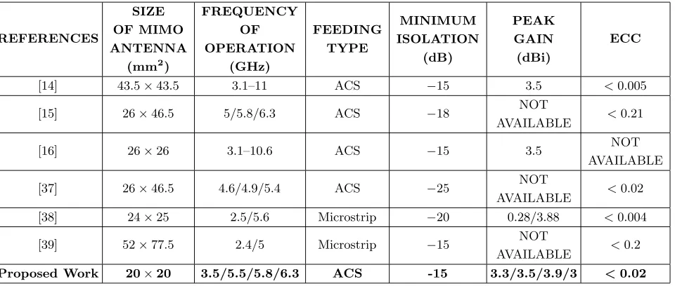
Table 2. Comparison between the proposed MIMO antenna design with other recently reported designs.
REFERENCES
SIZE OF MIMO ANTENNA
(mm2)
FREQUENCY OF OPERATION (GHz) FEEDING TYPE MINIMUM ISOLATION (dB) PEAK GAIN (dBi) ECC
[14] 43.5×43.5 3.1–11 ACS −15 3.5 <0.005
[15] 26×46.5 5/5.8/6.3 ACS −18 NOT
AVAILABLE <0.21
[16] 26×26 3.1–10.6 ACS −15 3.5 NOT
AVAILABLE
[37] 26×46.5 4.6/4.9/5.4 ACS −25 NOT
AVAILABLE <0.02
[38] 24×25 2.5/5.6 Microstrip −20 0.28/3.88 <0.004
[39] 52×77.5 2.4/5 Microstrip −15 NOT
AVAILABLE <0.2
Proposed Work 20×20 3.5/5.5/5.8/6.3 ACS -15 3.3/3.5/3.9/3 <0.02
3. CONCLUSION
A compact ACS-fed flipped MIMO antenna integrated in an actual USB module is proposed. The proposed F-shaped ACS-fed antenna has dual bands, which cover WiMAX-3.5/5.5 GHz, WLAN-5.8 GHz, and C-band-6.3 GHz. The proposed antenna is electrically small satisfying the constraints defined by Ch’s limit. The proposed ACS-fed MIMO antenna achieves fractional bandwidths of 22% and 20% in the lower and upper bands, respectively. The proposed antenna achieves gain of 3.3/3.5/3.9/3 dBi at frequencies 3.5/5.5/5.8/6.3 GHz, respectively thus yielding high gain for the available aperture. Stable radiation patterns in both the principal planes are obtained. Pattern diversity is achieved in the MIMO configuration. All the results validate that the proposed antenna is a suitable candidate for USB dongle applications.
REFERENCES
1. Su, S., J. Chou, and K. Wong, “Internal ultrawideband monopole antenna for wireless USB dongle applications,”IEEE Transactions on Antennas and Propagation, Vol. 55, No. 4, 1180–1183, Apr. 2007.
2. Rowell, C. and E. Y. Lam, “Mobile-phone antenna design,” IEEE Antennas and Propagation Magazine, Vol. 54, No. 4, 14–34, Aug. 2012.
3. Wong, K.-L., S.-W. Su, C.-L. Tang, and S.-H. Yeh, “Internal shorted patch antenna for a UMTS folder-type mobile phone,” IEEE Transactions on Antennas and Propagation, Vol. 53, No. 10, 3391–3394, Oct. 2005.
compact MIMO antenna for wireless local area network applications,” IET Microwaves, Antennas
& Propagation, Vol. 13, No. 4, 519–525, Mar. 27, 2019.
8. Zhou, G., “Shorting-pin loaded annular ring microstrip antenna,”IEEE Antennas and Propagation Society International Symposium, 1998 Digest. Antennas: Gateways to the Global Network, Held in conjunction with: USNC/URSI National Radio Science Meeting, Vol. 2, 900–903, Cat. No. 98CH36, Atlanta, GA, 1998.
9. Saurav, K., D. Sarkar, and K. V. Srivastava, “CRLH unit-cell loaded multiband printed dipole antenna,” IEEE Antennas and Wireless Propagation Letters, Vol. 13, 852–855, 2014.
10. Hawatmeh, D. F., S. LeBlanc, P. I. Deffenbaugh, and T. Weller, “Embedded 6-GHz 3-D printed half-wave dipole antenna,” IEEE Antennas and Wireless Propagation Letters, Vol. 16, 145–148, 2017.
11. Chouti, L., I. Messaoudene, T. A. Denidni, and A. Benghalia, “Triple-band CPW-fed monopole antenna for WLAN/WiMAX applications,”Progress In Electromagnetics Research Letters, Vol. 69, 1–7, 2017.
12. Saad, A., A. Ibrahim, O. Haraz, and A. Elboushi, “Tri-band compact ACS-fed meander-line antenna for wireless communications,” International Journal of Microwave and Wireless Technologies, Vol. 9, No. 9, 1895–1903, 2017.
13. Kumar, A., P. V. Naidu, and V. Kumar, “A compact uniplanar ACS fed multi band low cost printed antenna for modern 2.4/3.5/5 GHz applications,”Microsyst. Technol., Vol. 24, No. 3, 1413, 2018.
14. Qin, H. and Y.-F. Liu, “Compact UWB MIMO antenna with ACS-fed structure,” Progress In Electromagnetics Research C, Vol. 50, 29–37, 2014.
15. Ibrahim, A. A., M. A. Abdalla, and Z. Hu, “Compact ACS-fed CRLH MIMO antenna for wireless applications,” IET Microwaves, Antennas& Propagation, Vol. 12, No. 6, 1021–1025, 2018.
16. Zhang, J.-Y., F. Zhang, W.-P. Tian, and Y.-L. Luo, “ACS-fed UWB-MIMO antenna with shared radiator,”Electronics Letters, Vol. 51, No. 17, 1301–1302, 2015.
17. Wong, H., K. K. So, K. B. Ng, K. M. Luk, C. H. Chan, and Q. Xue, “Virtually shorted patch antenna for circular polarization,”IEEE Antennas and Wireless Propagation Letters, Vol. 9, 1213– 1216, 2010.
18. Wang, D., H. Wong, and C. H. Chan, “Small patch antennas incorporated with a substrate integrated irregular ground,” IEEE Transactions on Antennas and Propagation, Vol. 60, No. 7, 3096–3103, Jul. 2012.
19. Amani, N. and A. Jafargholi, “Zeroth-order and TM10 modes in one-unit cell CRLH mushroom
resonator,” IEEE Antennas and Wireless Propagation Letters, Vol. 14, 1396–1399, 2015.
20. Gauthier, G. P., A. Courtay, and G. M. Rebeiz, “Microstrip antennas on synthesized low dielectric-constant substrates,”IEEE Transactions on Antennas and Propagation, Vol. 45, No. 8, 1310–1314, Aug. 1997.
21. Zhang, C., J. Gong, Y. Li, and Y. Wang, “Zeroth-order-mode circular microstrip antenna with patch-like radiation pattern,” IEEE Antennas and Wireless Propagation Letters, Vol. 17, No. 3, 446–449, 2018.
22. Chu, L. J., “Physical limitations of omni-directional antennas,”Journal of Applied Physics, Vol. 19, 1163–1175, Dec. 1948.
2.4/5.2/5.8 GHz WLAN applications,”IEEE Transactions on Antennas and Propagation, Vol. 60, No. 12, 5924–5931, Dec. 2012.
28. Kumar Naik, K., “Asymmetric CPW-fed SRR patch antenna for WLAN/WiMAX applications,”
AEU — International Journal of Electronics and Communications, Vol. 93, 103–108, 2018. 29. Hu, W., J. Wu, S. Zheng, and J. Ren, “Compact ACS-fed printed antenna using dual edge
resonators for tri-band operation,” IEEE Antennas and Wireless Propagation Letters, Vol. 15, 207–210, 2016.
30. Patel, U. and T. K. Upadhyaya, “Design and analysis of compact μ-negative material loaded wideband electrically compact antenna for WLAN/WiMAX applications,” Progress In Electromagnetics Research M, Vol. 79, 11–22, 2019.
31. Mishra, N. and R. K. Chaudhary, “A miniaturized ZOR antenna with enhanced bandwidth for WiMAX applications,” Microw. Opt. Technol. Lett., Vol. 58, 71–75, 2016.
32. Deepu. V, R. K. Raj, M. Joseph, S. M. N., and P. Mohanan, “Compact asymmetric coplanar strip fed monopole antenna for multiband applications,” IEEE Transactions on Antennas and Propagation, Vol. 55, No. 8, 2351–2357, Aug. 2007.
33. Li, X., X. Shi, W. Hu, P. Fei, and J. Yu, “Compact triband ACS-fed monopole antenna employing open-ended slots for wireless communication,” IEEE Antennas and Wireless Propagation Letters, Vol. 12, 388–391, 2013.
34. Sharma, S. K., M. A. Abdalla, and Z. Hu, “Miniaturisation of an electrically small metamaterial inspired antenna using additional conducting layer,” IET Microwaves, Antennas & Propagation, Vol. 12, No. 8, 1444–1449, Jul. 4, 2018.
35. Sipal, D., M. P. Abegaonkar, and S. K. Koul, “Compact dual band-notched UWB MIMO antenna for USB dongle application with pattern diversity characteristics,” Progress In Electromagnetics Research C, Vol. 87, 87–96, 2018.
36. Mikki, S. M. and Y. M. M. Antar, “On cross correlation in antenna arrays with applications to spatial diversity and MIMO systems,”IEEE Transactions on Antennas and Propagation, Vol. 63, No. 4, 1798–1810, Apr. 2015.
37. Abdalla, M. A., D. Z. Nazif, and A. M. Ali, “Two elements MIMO antenna with asymmetric coplanar strip metamaterial configuration and EBG Hybrid Isolation,” 2018 12th International Congress on Artificial Materials for Novel Wave Phenomena (Metamaterials), 001–003, Espoo, 2018.
38. Nandi, S. and A. Mohan, “A compact dual-band MIMO slot antenna for WLAN applications,”
IEEE Antennas and Wireless Propagation Letters, Vol. 16, 2457–2460, 2017.