Design and Optimization of Structure of Tower-Type Coil in
Wireless Charging System for Electric Vehicles
Zhongqi Li1, Min Zhang1, Shoudao Huang2, and Jiliang Yi1, *
Abstract—Magnetic resonant wireless power transfer (WPT) is an emerging technology that may create new applications for wireless power charging. However, the output voltage and efficiency fluctuations resulting from lateral misalignments are main obstructing factors for promoting this technology. In this paper, a structure of tower-type coils is proposed. The mathematical model of the proposed structure is built based on equivalent circuit method. The expressions of the output voltage and efficiency are then derived by solving the system equivalent equations. In addition, a method of optimizing the mutual inductance between the transmission coil and intermediate coil and the strong-coupling parameters between the intermediate coil and receiving coil is proposed. The mutual inductance between the transmission coil and intermediate coil can be kept nearly constant with lateral misalignments, and the optimum strong-coupling parameter between the intermediate coil and the receiving coil can be obtained by the proposed method. Therefore, the output voltage and efficiency can be kept nearly constant with different lateral misalignments. The WPT system based on tower-type coils via magnetic resonance coupling is designed. Simulated and experimental results validating the proposed method are given.
1. INTRODUCTION
Electric vehicles (EVs) are receiving increasing attention in the international research community due to tougher regulations triggered by environment and energy security concerns. There are two charging modes for electric vehicles, including wired charging mode and wireless charging mode [1–4]. Compared to the wired charging mode of EVs, the convenience of wireless charging using magnetic resonance can make EVs more acceptable to drivers because they do not need to handle power plug. At the same time, EVs system using wireless charging mode can be safer [5–7].
Two conditions should be satisfied in a magnetic resonant wireless charging system to maintain the stability of a system [8]. First, the system efficiency is high [9]. Secondly, the output voltage or output current of the system is nearly constant. However, in practice, inevitable lateral and vertical misalignments between the transmission coil and receiving coil lead to variations of the mutual inductance between the transmission coil and receiving coil [10]. The efficiency is decreased, and the output voltage or output current may be changed as the mutual inductance between the transmission coil and receiving coil is changed [11]. The system efficiency was improved by adjusting equivalent load resistance with lateral and vertical misalignments [12]. The constant output voltage was also obtained by adjusting equivalent load resistance. However, the equivalent load resistance at maximum efficiency is not the same as that at constant output voltage for a given mutual inductance [13, 14]. In order to achieve simultaneously high efficiency and constant output voltage for a wireless charging system, a maximum efficiency point tracking control scheme was proposed to maximize system efficiency [15].
Received 12 May 2019, Accepted 26 July 2019, Scheduled 14 August 2019 * Corresponding author: Jiliang Yi (ieee [email protected]).
When the mutual inductance between the transmission coil and receiving coil is changed, the minimum DC input current can be tracked by real-time changing the duty cycle of the DC-DC converter (The minimum input current is an equivalent condition of the maximum efficiency when the input voltage and output voltage are kept constant). The output voltage is kept constant by changing the duty cycle of another DC-DC converter. However, two DC-DC converters are added to the wireless charging systems, and the system efficiency is decreased inevitably because two DC-DC converters have power losses. At the same time, it is difficult to track input current because the waveform of the input current is not standard.
There are other methods using new coil structures to deal with the adverse effect of misalignments on the efficiency and output voltage: 1) A narrow-width I-type power supply rail and pickups were proposed [16]. The experimental results showed that the output power was reduced and reached nearly 1 kW at the cross-point of the poles as the pickup moved away from the center of the pole along X -direction, and the output power exceeded 20 kW as the pickup laterally moved in Y-direction within 20 cm and became half at 24 cm from the center of the power supply rail. The system efficiency was 74%; 2) A large lateral displacement of 30 cm at an air gap of 20 cm was experimentally obtained by using ultraslim S-type power supply rails [17]. The load power reached the −3 dB point having half of its maximum load power with the lateral tolerance of 30 cm; 3) A new homogeneous WPT technique was proposed and implemented to maintain the output voltage constant for lateral and vertical misalignments systems [18, 19]. The homogeneous magnetic field should be paid with reduction of the quality factor of the transmitter because the transmitter is composed of many small coils (58 mm×58 mm×22.5 mm) [19]. The system efficiency is reduced when the quality factor of the transmitter is decreased [18]; 4) Reference [20] proposed an extremely asymmetric coil structure, including a big power supply coil set (110 cm×80 cm) and a small pick-up coil set. When the pick-up coil laterally deviated from the center of the power supply coil by 39 cm, the output voltage was reduced by about 29% from the maximum output voltage 150 V. In conclusion, it is necessary to further reduce output voltage pulsations and improve the efficiency for electric vehicles. In this paper, the structure of tower-type coils is proposed to reduce output voltage pulsations and improve the efficiency.
The remainder of the paper is outlined as follows. Section 2 gives the method of parameters calculated. Section 3 describes the two-coil WPT system. Section 4 proposes the structure of tower-type coils and builds the model of the proposed structure. Section 5 proposes a method of optimization parameters. Section 6 presents the experimental setup and the measurement results with lateral misalignments between the transmission coil and receiving coil. Section 7 draws the conclusion.
2. PARAMETERS CALCULATED
2.1. Calculated Mutual Inductance and Self-Inductance
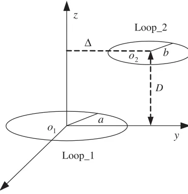
Figure 1 shows two loops with lateral misalignments between loop 1 and loop 2. D is the transmission distance,athe radius of loop 1,bthe radius of loop 2, and Δ the lateral misalignments between loop 1 and loop 2.
The mutual inductance and self-inductance of two loops whose axes are parallel can be expressed by the single integral [21–23]
M u(a, b,Δ, D) = πμ0 √ ab ∞ 0 J1
xa/b
J1
xa/b
×J0
x√Δ ab
exp
−x√D
ab
dx (1)
L(a, r) = μ0a ln 8a r −2 (2)
whereJ0 andJ1 are the Bessel functions of zeroth-order and first-order, respectively. r is the radius of
the copper. μ0 is the magnetic conductivity.
For a coil composed of multi-turn, the mutual inductance between the transmission coil and receiving coil can be calculated using
Mab= NA i=1 NB j=1
o1 D y z o2 a b Loop_1 Loop_2 Δ
Figure 1. Lateral misalignments between loop 1 and loop 2.
where NA and ai are the number of turns of the transmission coil and the radius of the transmission coil, respectively. NBandbj are the number of turns of the receiving coil and the radius of the receiving coil, respectively.
A multi-turn planar spiral coil can be approximately equivalent to the sum of a plurality of coaxial single-turn coils. Self-inductance of each coil can be calculated by Eq. (4).
La= NA
i=1
L(ai, r) + NA i=1 NA j=1
M u(ai, aj, D= 0,Δ = 0) (1−δi,j) (4)
whereδi,j = 1 withi=j orδi,j = 0 withi=j.
The coupling coefficient between each coil is defined as follows:
kab= √Mab
LaLb
, 0≤kab≤1 (5)
As shown in Eqs. (1) and (3), it can be seen that mutual inductance is dependent ona, b, D, and Δ. When a, b, and D are fixed, mutual inductance is only related to Δ. The bigger the value of Δ is, the smaller the mutual inductance becomes, and the coupling coefficient kab is decreased according to Eq. (5).
2.2. Calculated Resistance
The resistance of each coil is calculated as follows [24]:
R = Rdcstrand+Racstrand/ns−Rdcstrandβγs
2
ber2(γs)ber(γs) +bei2(γs)bei(γs)
ber2(γ
s) +bei2(γs)
+ N
i=1
nsSav iGstrandh2ext i (6)
where
Racstrand = Rdcstrandγs
2
ber(γs)bei(γs)−bei(γs)ber(γs)
ber2(γ
s) +bei2(γs)
Gstrand = −
2πγs
δ
ber2(γs)ber(γs) +bei2(γs)bei(γs)
ber2(γ
hexti is the magnetic field generated over the ith-turn of the coil when an RMS current of 1 A is in it.
γs = 1.414rs/δ, δ is the skin depth, rs the Litz-wire strand radius, and Rdcstrand the DC resistance of
the strand. ber, bei, ber, bei are the Kelvin functions, and ber2, bei2 are the second order of Kelvin
functions. Sav is the average length of the coil. ns is the number of strands of the Litz-wire.
3. PROPOSED STRUCTURE
3.1. Structure of Tower-Type Coils
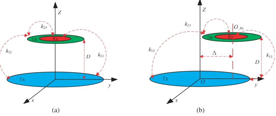
In this section, a structure of tower-type coils is proposed to deal with the effect of lateral misalignments on mutual inductance. The proposed structure contains three coils, which are transmission coil, intermediate coil, and receiving coil, labeled as Tx, Im, and Rx, as shown in Fig. 2(a). Im and Rx can be placed on the same plane, or Rx can be placed on the plane staying away from Tx. D is the transmission distance between the Tx and Im. kij is the coupling coefficient betweeni-th coil andj-th coil (i=j;i, j= 1, 2, 3). Subscript 1 denotes Tx; subscript 2 denotes Im; subscript 3 denotes Rx. The transmission coil is bigger than the intermediate coil in size, and the intermediate coil is bigger than the receiving coil. k13 is smaller thank12because the intermediate coil is bigger than the receiving coil.
Therefore, k13 may be neglected in the next analysis.
(a) (b)
Figure 2. The proposed structure. (a) Structure of tower-type coils. (b) Structure of tower-type coils with misalignment.
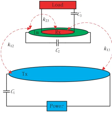
Figure 2(b) shows the proposed structure with misalignments. Δ is the lateral misalignments between Tx and Im. In general, the variations of Δ may result in the changes of mutual inductance or the coupling coefficient. However, the variations of the mutual inductances between the Tx and Im are very smooth with misalignments when the proposed structure is used. The system can maintain high efficiency and constant output voltage because mutual inductances between the Tx and Im are nearly constant with misalignments. In Section 3, how to maintain the mutual inductance constant will be further discussed. The overall structure of the proposed structure is shown in Fig. 3. It is composed of a power, Tx , Im, Rx, and Load. Ci is the resonance capacitor (i= 1, 2, 3). The main flow of power is as follows: First, the power source via the compensation capacitor C1 is connected in series to the
transmission coil Tx. Secondly, the power is transferred from Tx to Im using magnetic fields. And the power is transferred from Im to Rx. Finally, the power is transferred from Rx to the Load.
The proposed WPT system can be represented in terms of lumped circuit elements (L,C,M, and
R), as shown in Fig. 4. R1 is the parasitic resistance of Tx, R2 the parasitic resistance of Im,R3 the
parasitic resistance of Rx, Rs the internal resistance of the power source, RL the load resistance, L1
Figure 3. The overall structure of the proposed structure.
Figure 4. The equivalent circuit model for the WPT system. Each coil is modeled as series resonators.
capacitance of Tx, C2 the external compensating capacitance of Im, C3 the external compensating
capacitance of Rx,M12the mutual inductance between Tx and Im,M13the mutual inductance between
Tx and Rx,M23 the mutual inductance between Im and Rx, Vs the voltage of the power, and Vout the voltage of the load.
3.2. Mathematical Model of Proposed Structure
By applying Kirchhoff’s voltage law (KVL), the proposed WPT system is presented as follows:
⎧ ⎨ ⎩
Z1I1+jωM12I2+jωM13I3=Vs
jωM12I1+Z2I2+jωM23I3= 0
jωM13I1+jωM23I2+Z3I3= 0
(7)
⎧ ⎨ ⎩
Z1 =R1+Rs+jωL1+ 1/(jωC1)
Z2 =R2+jωL2+ 1/(jωC2)
Z3 =R3+RL+jωL3+ 1/(jωC3)
The current expressions of each coil can be obtained by solving Eqs. (7) and (8) ⎧ ⎪ ⎪ ⎪ ⎪ ⎪ ⎪ ⎪ ⎨ ⎪ ⎪ ⎪ ⎪ ⎪ ⎪ ⎪ ⎩
I1 = M
2
23ω2Vs+Z2Z3Vs
ω2M2
12Z3+ω2M132Z2+ω2M232 Z1+Z1Z2Z3−2jω3M12M23M13
I2 =− ω
2M
13M23Vs+jωM12Z3Vs
ω2M2
12Z3+ω2M132Z2+ω2M232 Z1+Z1Z2Z3−2jω3M12M23M13
I3 =− ω
2M
12M23Vs+jωM13Z2Vs
ω2M2
12Z3+ω2M132Z2+ω2M232 Z1+Z1Z2Z3−2jω3M12M23M13
(9)
whereI1 is the current of Tx, I2 the current of Im, and I3 the current of Rx.
According to Eq. (9), the output voltageVL is as follows:
VL=I3RL=−
ω2M12M23Vs+jωM13Z2Vs
RL
ω2M2
12Z3+ω2M132 Z2+ω2M232 Z1+Z1Z2Z3−2jω3M12M23M13
(10)
According to Eqs. (7)–(10), the transmission efficiency is as follows:
η=I
2 3RL
VSI1
= (ω
2M
12M23+jωM13Z2)2RL (ω2M2
23+Z2Z3)(ω2M122Z3+ω2M132 Z2+ω2M232Z1+Z1Z2Z3−2jω3M12M23M13)
(11)
When the M12 is changed, according to Eq. (10) the output voltage can be obtained, and the
transmission efficiency can be obtained according to Eq. (11).
Assuming the frequency of each coil is the same, the efficiency expression (11) and output voltage expression (10) can be simplified as follows:
η = (U1U2+jU3)
2U
L
(U22+UL+ 1)(U12(1 +UL) +U22(1 +Us) +U32+ (1 +Us)(1 +UL)−2jU1U2U3)
(12)
VL =
(U1U2+jU3)VsUL
U2
1(1 +UL) +U32+U22(1 +Us) + (1 +Us)(1 +UL)−2jU1U2U3
R3/R1 (13)
where the source matching factor is defined as Us = Rs/R1, the load matching factor defined as
UL = RL/R3, the strong-coupling parameter between Tx and Im defined as U1 = k12(Q1Q2)1/2, the
strong-coupling parameter between Im and Rx defined as U2 = k23(Q2Q3)1/2, the strong-coupling
parameter between Tx and Rx defined as U3 =k13(Q1Q3)1/2, the unload quality factor of the Tx coil
defined as Q1 = ωL1/R1, the unload quality factor of the Im coil defined as Q2 = ωL2/R2, and the
unload quality factor of the Rx coil defined as Q3=ωL3/R3.
When the coupling coefficient k13 is neglected, the efficiency expression (12) and output
expression (13) can be simplified as follows:
η = (U1U2)
2U
L (U2
2 +UL+ 1)(U12(1 +UL) +U22(1 +Us) + (1 +Us)(1 +UL))
(14)
VL = U1U2ULVs
U12(1 +UL) +U22(1 +Us) + (1 +Us)(1 +UL)
R3/R1 (15)
According to Eqs. (14) and (15), the efficiency and output voltage are dependent on U1, U2, Us, and UL. In general, Us and UL are nearly constant for a given load resistance and parameters of Tx ,Im, and Rx coil; therefore,U1and U2are key parameters to obtain high efficiency and maintain output
voltage constant.
By differentiating η with respect toU2 and equating the differential function to zero
∂η ∂U2
= 0 (16)
The optimum strong-coupling parameter between Im and Rx for the optimum efficiency can be obtained as follows:
U2 opt=
2UL+Us+ 2ULU + 2U12UL+UL2Us+U12+UL2+U12UL2+ 1
Us+ 1
1 4
4. METHOD OF PARAMETER OPTIMIZATION
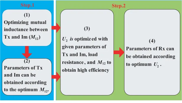
In this section, a method of optimizing M12 and U2 is proposed in order to obtain high efficiency and
maintain output voltage constant. The process of the method of optimizingM12 (U1) andU2 is shown
in Fig. 5.
(1) Optimizing mutual inductance between Tx and Im (M12)
(2) Parameters of Tx and Im can be obtained according to the optimum M12.
(3)
U2 is optimiz ed with
given parameters of Tx and Im, load resistance , and M12to
obtain high efficiency
(4)
Parameters of Rx can be obtained according to optimum U2.
Step.1 Step.2
Figure 5. The process of the method of optimizingM12 and U2.
Step 1. Optimizing M12: M12 may be constant in the proposed structure to optimize the outer
diameters and the numbers of turns of Tx and Im with misalignments. According to the optimumM12,
parameters of Tx and Im (diameters of Tx and Im, the numbers of turns of Tx and Im) can be obtained. Step 2. OptimizingU2: U1,UL, and Us can be obtained according to the optimum M12, optimum
parameters of Tx and Im (diameters, turns), and the load resistance. The value ofU2optcan be obtained according to Eq. (17). The outer diameter of Rx and the number of turns of Rx are optimized in order to obtain U2opt.
4.1. Optimizing M12
It can be seen from Eq. (15) that the output voltageVLis dependent onU1,U2,UL,Us, and (R3/R1)1/2.
In general, U1,U2,UL, Us, and (R3/R1)1/2 are nearly constant when the parameters (R, L, C) of each
coil and the load are given. However, The mutual inductanceM12may be changed with the variations of
lateral misalignments (The variations ofM12 result in the changes of U1 and U2, respectively). Lateral
misalignments between Im and Rx may not occur, and M23 may be kept constant when both Im and
Rx are fixed at the same plane by using the proposed structure. Lateral misalignments between Tx and Im or Rx may occur. Therefore, how to maintain the mutual inductanceM12(or U1) constant is a
problem. In this section, the method of the mutual inductance optimization is proposed. The mutual inductance M12 (or U1) can be kept nearly constant with lateral misalignments by using the proposed
method.
The process of the method of mutual inductance optimization is as follows:
1) Parameters setting: the resonant frequency is set to 85 kHz. The mutual inductance between the transmission coil and intermediate coil should be large enough to obtain high efficiency. The mutual inductance is set to 6.0µH. The transmission distance is set to 15 cm. The diameter of copper is set to 2.3 mm. The outer diameter of Tx is changed from 0.25 m to 0.30 m in a step of 2.0 mm. The outer diameter of Im is changed from 0.2 m to 0.25 m in a step of 2.0 mm. The number of turns of Tx is changed from 17 to 40 in a step of 1. The number of turns of Im is changed from 6 to 10 in a step of 1. 2) Calculated mutual inductance: According to Eqs. (1) and (2), the mutual inductance between Tx and Im can be obtained with different lateral misalignments. M1210 is the mutual inductance between
Tx and Im when lateral misalignment equals 10 cm;M120 is the mutual inductance between Tx and Im
Figure 6. The flowchart of the method of the mutual inductance optimization.
3) Compared to ε (ε= (M120−M1210)/M120) at a given outer diameter of Tx, outer diameter of
Im, the number of turns of Tx, and the number of turns of Im, the optimumεis obtained (The smaller
Figure 7. The optimum parameters of each coil. N1 is the the number of turns of Tx,N2 is the number
of turns of Im, a1 is the out radius of Tx,a2 is the out radius of Im.
Figure 8. The optimum mutual inductanceM120,M1210 andε.
4) According to the optimumε, optimum parameters of Tx and Im can be obtained. The detailed optimization process is shown in Fig. 6.
Figure 7 shows optimum parameters of each coil (N1,N2, a, b). It can be seen that optimum N1
is equal to 17, optimum N2 equal to 10, optimum a1 equal to 0.3 m, and optimum a2 equal to 0.1 m.
Fig. 8 shows optimum mutual inductance M120, M1210, and ε. It is clearly seen that all εare smaller
than 5%;optimumεis 3.1%; all mutual inductances are larger than 6.0µH. In the above analysis, it can be seen that the radius of Im should be decreased, and the number of turns of Im should be increased in order to obtain constant mutual inductance.
4.2. Optimizing U2
U2 is also a key parameter to obtain high efficiency, and optimum U2 can be obtained by Eq. (17) with
given U1,UL, and Us. Parameters of Rx (the number of turns of RxN3 and the outer diameter of Rx
a3) can be obtained according to optimumU2.
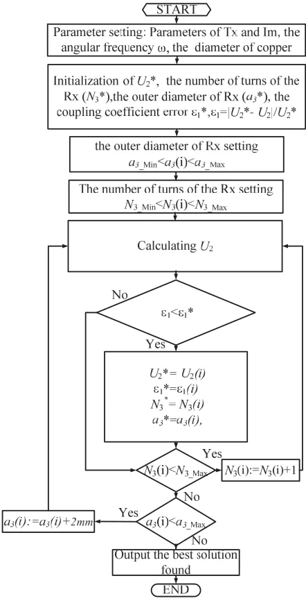
The process of the method of optimizing U2 is as follows: 1) Parameters setting: the resonant
frequency is set to 85 kHz. The diameter of copper is set to 2.3 mm. OptimumN1is set to 17, optimum
N2 set to 10, optimum a1 set to 0.3 m, and optimum a2 set to 0.1 m. The outer diameter of Rx is
in a step of 1 turn (The diameter of each turn is 2.3 mm). 2) Calculate strong-coupling parameters U2:
a) According to Eqs. (1)–(3), the mutual inductance between Im and Rx (M12) can be obtained.
b) The self-inductances of Tx, Im, and Rx can be obtained according to Eqs. (3) and (4). c) The coupling coefficients (k12 and k13) can be obtained according to Eq. (5).
d) The resistances of Tx, Im, and Rx can be obtained according to Eq. (6).
e) The unload quality factors of Tx, Im, and Rx can be obtained according to Q1 = ωL1/R1,
Q2=ωL2/R2, and Q3 =ωL3/R3.
f) U2 can be obtained according to U2 =k23(Q2Q3)1/2.
3) Compare ε1 with ε∗1(ε1 = (U2∗−U2)/U2∗) at a given outer diameter of Rx and the number of
turns of Rx. The optimumε1 can be obtained.
4) According to optimumε1, optimum parameters of Rx can be obtained. The detailed optimization
process is shown in Fig. 9.
(a) (b)
(c) (d)
(e)
(f)
5. EXPERIMENTAL AND SIMULATION RESULTS
5.1. Experimental Setup
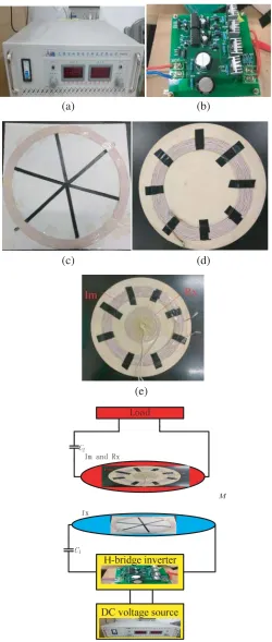
To validate the proposed structure and optimization method, the prototype model of the system has been built, as shown in Fig. 10. It is composed of a DC voltage source, a transmission resonant coil, an intermediate coil, a receiving resonant coil, an H-bridge inverter, and the load. The value of the DC voltage source is 36 V. The DC voltage source is shown in Fig. 10(a). H-bridge inverter is used at the transmitter side to provide AC excitation, as shown in Fig. 10(b). It contains four MOSFETs (IRF3207). The transmission resonant coil is shown in Fig. 10(c). The intermediate resonant coil is shown in Fig. 10(d). The intermediate resonant coil and receiving resonant coil are shown in Fig. 10(e). According to the optimization method, the outer diameter of the transmission resonant coil is 0.6 m with a pitch of 0 cm for approximately 17 turns; the outer diameter of intermediate resonant coil is 0.2 m with a pitch of 0 cm for approximately 10 turns; the outer diameter of receiving resonant coil is 0.09 m with a pitch of 0 cm for approximately 16 turns. All coils are made from 300-strand AWG 38Litz-wire.
Table 1. Measured parameters of the resonant coils.
Symbol Parameter Value
L1 the inductance of Tx 333.7µH
L2 the inductance of Im 30.5µH
L3 the inductance of Rx 10.9µH
C1 the compensation capacitance of Tx 10.5 nF
C2 the compensation capacitance of Im 115.0 nF
C3 the compensation capacitance of Rx 321.6 nF
R1 the parasitic resistance of Tx 0.402 Ω
R2 the parasitic resistance of Im 0.067 Ω
R3 the parasitic resistance of Rx 0.04 Ω
f0 the original resonant frequency 85.0 kHz
(a) (b)
An impedance analyzer is used to extract the parameters in Eqs. (7) and (8). The original resonant frequency is set to 85.0 kHz. The load resistance is set to 3.7 Ω with a tower-type coil WPT system. The transmission distance is 15 cm. Parameters of the resonant coils are listed in Table 1. The moving direction of the receiver is noted asy-axis, and the coordinates are marked in Fig. 2(b).
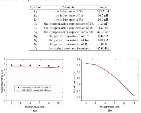
Figure 11(a) shows the measured and calculated mutual inductances between Tx and Im versus misalignments with the proposed structure. It can be seen that the mutual inductance between Tx and Im (M12) is changed from 6.89µH to 6.63µH as the misalignment is varied from 0 cm to 10 cm. The
difference betweenM120andM1210is 0.26µH.εis equal to 3.77% according toε= (M120−M1210)/M120.
The variations of mutual inductance are very smooth as the misalignment is varied from 0 cm to 10 cm. Fig. 11(b) shows the calculated mutual inductance between the transmission coil and receiving coil versus misalignments with the traditional structure (Both the transmission coil and receiving coil are the same as Im in size). It can be seen that the mutual inductance between the transmission coil and receiving coil is changed from 1.13µH to 0.63µH as the misalignment is varied from 0 cm to 10 cm. ε
is equal to 44.24%. The variations of mutual inductance with the proposed structure are smaller than those of the traditional structure.
5.2. Two-Coil Structure
In the two-coil WPT system, Tx is the transmission coil, and Im is used as receiving coil. The load resistance is set to 10 Ω in order to obtain the optimum efficiency [11], and the value of the DC voltage source is set to 48 V.
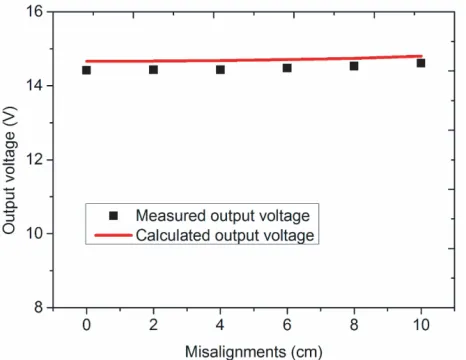
Figure 12 shows the measured and calculated output voltages versus misalignments with the two-coil WPT system. It can be seen that the output voltage is changed from 14.40 V to 14.60 V as the misalignment is varied from 0 cm to 10 cm. The output voltage is nearly constant as misalignment is varied from 0 cm to 10 cm. Fig. 13 shows the measured and calculated efficiencies versus misalignments with the two-coil WPT system. It can be seen that the efficiency is changed from 65.6% to 63.5% as the misalignment is varied from 0 cm to 10 cm. The efficiency is also nearly constant as the misalignment is varied from 0 cm to 10 cm.
Figure 12. Measured and calculated output voltage versus misalignments.
Figure 13. Measured and calculated efficiency versus misalignments with two-coil WPT system.
5.3. Structure of Tower-Type Coils
All parameters of the tower-type coil system are shown in Table 1 and Fig. 11. The strong-coupling parameter between Im and Rx U2 can be obtained according to U2 =k23(Q2Q3)1/2, and the actualU2
is equal to 34.2. OptimumU2 can also be calculated in terms of Eq. (17), and optimumU2 equals 36.9.
The effect of M13 (U13) on the output voltage and efficiency is small in this paper according to
the following calculated results. In order to analyse the effect of M13 (U13) on the output voltage and
efficiency, the calculated results can be obtained with the help of MATLAB in terms of Eqs. (12)–(16). Fig. 14(a) shows the calculated output voltage with consideringM13and without consideringM13. The
output voltage with considering M13 is changed from 14.46 V to 15.79 V as the misalignment is varied
from 0 cm to 12 cm. The output voltage without considering M13 is changed from 15.13 V to 16.24 V
as the misalignment is varied from 0 cm to 12 cm. The value of the output voltage with considering
M13is nearly the same as that without consideringM13. Fig. 14(b) shows the calculated efficiency with
considering M13 and without considering M13. The efficiency with considering M13 is changed from
87.5% to 86.8% as the misalignment is varied from 0 cm to 12 cm. The efficiency with consideringM13
is changed from 87.0% to 86.4% as the misalignment is varied from 0 cm to 12 cm. The value of the efficiency with consideringM13 is also nearly the same as that without consideringM13.
(a) (b)
Figure 14. Calculated output voltage and efficiency versus misalignments. (a) Calculated output voltage versus misalignments. (b) Calculated efficiency versus misalignments.
The misalignment Δ is set to 0 cm, 2 cm, 4 cm, 6 cm, 8 cm, 10 cm, and 12 cm, respectively. We test the input voltage, input current, the current of Im, and output voltage, respectively. Fig. 15 shows measured and calculated input currents versus misalignments. It can be seen that the input current is changed from 1.76 A to 1.89 A as the misalignment is varied from 0 cm to 12 cm. The input current of ratio of change is only 6.8%. It is convenient to design the transmission coil because the input current of ratio of change is small.
Figure 16 shows measured and calculated currents of Im versus misalignments. It can be seen that the current of Im is changed from 8.62 A to 9.02 A as the misalignment is varied from 0 cm to 12 cm. Compared with the value of the input current, the value of the current of Im is higher. This is beneficial for increasing the magnetic field strength of the Im coil. Therefore, the efficiency may be improved. And it is helpful for reducing the MOSFET of current stress.
Figure 17 shows the measured and calculated output voltages versus misalignments. It can be seen that the output voltage is changed from 14.07 V to 14.36 V as the misalignment is varied from 0 cm to 12 cm. The output voltage is nearly constant as the misalignment is varied from 0 cm to 12 cm. Fig. 18 shows the measured and calculated efficiencies versus misalignments. It can be seen that the efficiency is changed from 82.9% to 80.4% as the misalignment is varied from 0 cm to 12 cm. The output voltage and efficiency are nearly constant because the mutual inductance between Tx and Im (M12) is nearly constant as the misalignment is varied from 0 cm to 12 cm. Compared to a two-coil
Figure 15. Measured and calculated input current versus misalignments.
Figure 16. Measured and calculated current of Im versus misalignments.
Figure 17. Measured and calculated output voltage versus misalignments.
Figure 18. Measured and calculated efficiency versus misalignments.
Table 2. Performance comparison.
References
Size of Tx (Length ×width)
Size of Rx (Length ×width)
Lateral misalignments
(cm)
Ratio of output power (%)
Ratio of efficiency
(%)
Maximum efficiency
(%)
[14] 30 cm×20 cm 100 cm×80 cm X-direction: 24
Y-direction: / 50.0 30.0 74.0
[15] 20 cm×10 cm 100 cm×80 cm X-direction: 30
Y-direction: 15 50.0 30.1 71.0
[18] 110 cm×90 cm 70 cm×20 cm X-direction: 39
Y-direction: 18 29 / /
[Our work] Radius: 30 cm Radius: 4.5 cm X-direction: 12
misalignment is not the largest in this paper. However, the sizes of Tx and Rx are the smallest; the change rates of efficiency and power are the smallest; the misalignment of X-direction is the same as that of Y-direction; and the output voltage is kept nearly constant without the voltage regulator with misalignments. According to SAE J2954 standard, the misalignment in X direction is 10 cm, and the misalignment in Y direction is 7.5 cm. Therefore, the misalignments in both X and Y directions meet SAE J2954 standard by using the structure of tower-type coils.
6. CONCLUSION
In this paper, a structure of tower-type coils is proposed. The mathematical model of the proposed structure with lateral misalignments is built based on equivalent circuit method. The mutual inductance between the transmission coil and intermediate coil is kept nearly constant as the misalignment is varied from 0 cm to 12 cm, and the optimum strong-coupling parameter U2 is also obtained according to the
proposed optimization method. Both the output voltage and efficiency are nearly constant with different lateral misalignments by using the proposed structure and method. Experimental results show that the mutual inductance of the transmission coil and intermediate coil is changed from 6.88µH to 6.63µH, the output voltage ranged from 14.07 V to 14.36 V, and the efficiency changed from 82.9% to 80.4% as the misalignment is varied from 0 cm to 12 cm in the tower-type coil WPT system. We will further increase the lateral misalignments to meet the needs of the dynamic wireless power transfer system.
ACKNOWLEDGMENT
This work was supported in part by the National Natural Science Foundation of China under Grant 51377001, in part by the Hunan Provincial Department of Education under Grant17C0469, in part by Hunan Provincial Natural Science Foundation of China under Grant 2018JJ3127, in part by Zhuzhou City Natural Science Foundation of China.
REFERENCES
1. Musavi, F. and W. Eberle, “Overview of wireless power transfer technologies for electric vehicle battery charging,”IET Power Electronics, Vol. 7, 60–66, 2014.
2. Mi, C. C., G. Buja, S. Y. Choi, and C. T. Rim, “Modern advances in wireless power transfer systems for roadway powered electric vehicles,”IEEE Transactions on Industrial Electronics, Vol. 63, 6533– 6545, 2016.
3. Li, J., Y. Lu, F. Liu, B. Mu, Z. Dong, S. Pan, and C. Zheng, “Optimization method of magnetic coupling resonant wireless power transfer system with single relay coil,” Progress In Electromagnetics Research M, Vol. 80, 57–70, 2019.
4. Liu, B. J., H. T. Xu, and X. W. Zhou, “Resource allocation in wireless-powered mobile edge computing systems for internet of things applications,” Electronics, Vol. 8, No. 2, 206, Feb. 2019. 5. Choi, S. Y., B. W. Gu, S. Y. Jeong, and C. T. Rim, “Advances in wireless power transfer systems
for roadway-powered electric vehicles,” IEEE Journal of Emerging and Selected Topics in Power Electronics, Vol. 3, 18–36, 2015.
6. Li, Z., C. Zhu, J. Jiang, K. Song, and G. Wei, “A 3-kW wireless power transfer system for sightseeing car supercapacitor charge,” IEEE Transactions on Power Electronics, Vol. 32, 3301–3316, 2017. 7. Wang, T. F., X. Liu, N. Jin, H. J. Tang, X. J. Yang, and M. Ali, “Wireless power transfer for
battery powering system,”Electronics, Vol. 7, No. 9, 178, Sep. 2018.
8. Zhang, Y., K. Chen, F. He, Z. Zhao, T. Lu, and L. Yuan, “Closed-form oriented modeling and analysis of wireless power transfer system with constant-voltage source and load,” IEEE Transactions on Power Electronics, Vol. 31, 3472–3481, 2016.
10. Fotopoulou, K. and B. W. Flynn, “Wireless power transfer in loosely coupled links: Coil misalignment model,” IEEE Transactions on Magnetics, Vol. 47, 416–430, 2011.
11. Wang, J., J. Li, S. L. Ho, W. N. Fu, Y. Li, H. Yu, and M. Sun, “Lateral and angular misalignments analysis of a new PCB circular spiral resonant wireless charger,”IEEE Transactions on Magnetics, Vol. 48, 4522–4525, 2012.
12. Huang, S. D., Z. Q. Li, and Y. Li, “Transfer efficiency analysis of magnetic resonance wireless power transfer with intermediate resonant coil,”Journal of Applied Physics, Vol. 115, May 7, 2014. 13. Zhang, Y., T. Lu, Z. Zhao, F. He, K. Chen, and L. Yuan, “Employing load coils for multiple loads of resonant wireless power transfer,”IEEE Transactions on Power Electronics, Vol. 30, 6174–6181, 2015.
14. Zhang, Y., T. Lu, Z. Zhao, K. Chen, F. He, and L. Yuan, “Wireless power transfer to multiple loads over various distances using relay resonators,” IEEE Microwave and Wireless Components Letters, Vol. 25, 337–339, 2015.
15. Li, H., J. Li, K. Wang, W. Chen, and X. Yang, “A maximum efficiency point tracking control scheme for wireless power transfer systems using magnetic resonant coupling,” IEEE Transactions on Power Electronics, Vol. 30, 3998–4008, 2015.
16. Huh, J., S. W. Lee, W. Y. Lee, G. H. Cho, and C. T. Rim, “Narrow-width inductive power transfer system for online electrical vehicles,”IEEE Transactions on Power Electronics, Vol. 26, 3666–3679, 2011.
17. Choi, S. Y., S. Y. Jeong, B. W. Gu, G. C. Lim, and C. T. Rim, “Ultraslim S-type power supply rails for roadway-powered electric vehicles,” IEEE Transactions on Power Electronics, Vol. 30, 6456–6468, 2015.
18. Waffenschmidt, E., “Homogeneous magnetic coupling for free positioning in an inductive wireless power system,” IEEE Journal of Emerging and Selected Topics in Power Electronics, Vol. 3, 226– 233, 2015.
19. Zhang, Z. and K. T. Chau, “Homogeneous wireless power transfer for move-and-charge,” IEEE Transactions on Power Electronics, Vol. 30, 6213–6220, 2015.
20. Su, Y. C., H. Jin, W. Y. Lee, and C. T. Rim, “Asymmetric coil sets for wireless stationary EV chargers with large lateral tolerance by dominant field analysis,” IEEE Transactions on Power Electronics, Vol. 29, 6406–6420, 2014.
21. Ram Rakhyani, A. K., S. Mirabbasi, and M. Chiao, “Design and optimization of resonance-based efficient wireless power delivery systems for biomedical implants,” IEEE Transactions on Biomedical Circuits and Systems, Vol. 5, 48–63, 2011.
22. Soma, M., D. C. Galbraith, and R. L. White, “Radio-frequency coils in implantable devices: misalignment analysis and design procedure,” IEEE Transactions on Biomedical Engineering, Vol. 34, 276–282, 1987.