Influence of Skew Angle on RC-T Girder Bridge
Bhupendra Solanki
& Megha Thomas
1P.G. Students (M.Tech-Structures), P.I.E.T., LIMDA- 391760, Gujrat, India.
bhupendra.19933@gmail.com
2Associate Professor, Parul Institute of Engineering & Technology, Limda-391760, Gujarat, India.
meghathomas77@gmail.com
A
bstract
The Presence of skew in a bridge makes the design and analysis of bridge complex. The skew angle has a considerable effect on the behaviour of the bridge. Newly design bridges are mostly skew. This is due to constrain in congested urban area. Skew bridge allows a large variety of solution in roadways alignment. This contributes to a small environment impact on new road construction project. It can also be needed for the geographical constrain such as mountain terrain. However, the force flow in skew bridge is much more complicated than right angle bridge. Analytical calculation alone not provide sufficient for structural design. Numerical analysis need to be performed, in which a skew bridge can be modelling in several ways with different degree. Objective of the study is to understand the effect of skew on design of bridge and understand different technique related to the work has been done for skew on skew bridge. Analytical study is carried out on model to understand the behaviour of bridge on different loading condition and span. Study is on skew angle, span, loads (Dead & Live load) as per IRC guidelines. For the analysis finite element based CsiBridge Software is use.
Keywords- Skew Bridge, Skew Angle, Finite Element
Method, IRC Loading.
I.
I
NTRODUCTION
Bridges are a crucial part of the overall transportation system as they play very important roles in evacuation and emergency routes for rescues, first-aid, firefighting, medical services and transporting disaster commodities to expatriates. Skew bridges are inevitable for planning and design of road networks to maintain the straight alignment and geometry for safe and efficient traffic flow. Nowadays, the number of skew bridges is increasing all over the world to implement the road alignment straight as much as possible. As their structural behaviour and properties are different from the non-skewed bridges, proper attention
and measure should be taken to understand the design a safe bridge system for uninterrupted traffic flow. It is generally accepted that the skewed bridge exhibits complex response characteristics due to seismic excitations, especially when the skew angles are greater than
30 degrees. Load’s take shortest way to reach it’s nearest support that is obtuse corner of the bridge deck so there is more reaction on obtuse corner as compare to acute corner.
Fig.1. Skew Bridge
every gride size, in grillage analysis the slab is discretized in grid of Interconnecting beam and in finite element method the
Slab is discredited in grid of interconnecting plate. In the Comparison of both the method, grillage method is easy to use and not consuming more time as compare to the FEM and finite element method required more effort and time in modelling than grillage, and give the accurate result.
There are various types of forces are acting on the bridges like wind, seismic, dead, live loads etc. these forces produce different reaction as compare to the normal bridge because in normal bridge load reaction and distribution is uniform and in skew bridge the geometry of the bridges is not straight so the distribution of forces is not uniform, non-uniformity in force distribution it affected the stability of the bridge. The forces acting on the bridge is acting on a particular angle, it affect the stability and the maximum reaction is acting at the obtuse corner and lesser on other end.
The seismic behaviour of skewed bridges is affected by a number of factors including bridge skew angle, deck width, deck flexibility, number of span, number of column per bent, column ductility, soil-abutment-superstructure interaction. Also seismic response of bridge is strongly influenced by the column boundary condition. Due to skewness, the bridge does not only produce response in the direction of applied force but also give response along the other direction. This behaviour is due to coupling effect which lead to rotation and finally resulting into an increase in the skew angle. The effect of torsion cannot be neglected along with other internal forces as the skew angle increased.
The seismic forces affect the strength of the pier-column, shear capacity of the pier-column section is heavily dependent on axial, moment and shear demand. The abutment Shear key are designed to support the bridge deck in the transverse direction and act as a fuse in order to protect the abutment piles failure during a seismic activity. The dynamic interaction between the abutment backwall and deck in the longitudinal direction and the abutment shear key in the transverse direction is modelled by the gap element between the abutment backfill and bridge deck, gap element between the abutment shear key and bridge deck, nonlinear spring in the transverse direction represent the abutment shear key and nonlinear spring in the longitudinal direction represent the abutment backfill. The abutment of the bridge are constrained in the vertical direction, while free to move in the horizontal longitudinal and transverse direction. Ground motion with asymmetrical
high amplitude velocity pulse characteristics have the tendency of producing a biased, one sided response of the bridge structure. Asymmetrical impulsive loading generates larger displacement in one direction leading to a significant rotation and residual displacement on the bridges with skew abutment
II.
M
ODELLING And
A
NALYSIS
The analysis of bridge can be done using a Grillage analoge and finite element method. Grillage analog method is simple method and easy to use, in the grillage method the object is discretized in grid of inter connecting beam. Grillage methods take less time and not so complicated as FEM. On the other hand FEM, in the FEM the object is discretized in grid of inter connecting plates. Analysis of the object in FEM takes time and required more work but it give more accurate result.
For the analysis finite element based software CsiBridge is using, Finite element method is a versatile method,It can handle structure of complicated shapes and boundary condition. The analysis is on the single span concrete T-girder bridge, using a same span length with varying skew angle and understand the response of the bridge and load distribution. For the analysis using a skew angle with a interval of 0°,10°, 20°,30°,40°,50° and 60° are the angles for the analysis. Bridge model is analysed for both static and dynamic loads. All the structural data is decided based on the IRC standards, The live load combination is decide on the basis of table(Fig 2) given in the IRC:6-2014 . There are different load combination are given based on their geometrical parameter. In this study, as per IRC, One 70R loading and Class A or 3 class A whichever is maximum, will govern the live loading.
Fig.2. Live load combination
Fig.3. Class A - 3 Lanes
Fig 4. Class A - 1 Lanes + Class 70R (W)
Geometrical & Material data :-
Fig.5. Bridge cross section
Fig.6. Skew bridge mode
Bending Moment
Fig.7. Inner Girder B.M.
Support = Simply supported Length of bridge = 30 m
No of lane = 3 Wearing coat = 80mm Grade of concrete = M 25 Grade of steel = Fe-415 Width of carriageway = 10.5m Total width = 11.7m Diaphragms = At 5m interval Slab thickness = 0.2m
Fig.8. Outer Girder B.M.
Figure 7, 8 shows that the bending moment of inner girder decreases gradually when we increases the skew angle. Upto the 30 degree there is a no more change in bending moment graph but after 30 degree noticeable decrease in graph. Bending moment due to live load is decreases similar to the dead load bending moment.
Shear Force
Fig.9 Inner Girder S.F.
Fig.10 Outer Girder S.F.
Figure 9,10 shows that the shear force due to live load increase is more as compare to the dead load shear force with increase in skew angle.
After the 10 degree there is a sudden increase in shear force for both dead and live load and increase gradually after that.
Torsion
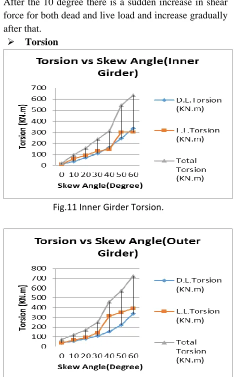
Fig.11 Inner Girder Torsion.
Fig.12 Outer Girder Torsion.
Figure 11,12 shows that the torsion at 0 degree is approx. zero and increase gradually up to 30 degree but after that there is a sudden increment in a values. The live load torsion value is more as compare to the dead load and also live load value increment is sudden, dead load is gradually increases.
Fig.14. 30° Skew angle.
Fig.15. 60° Skew angle
Stress distribution in the normal right angle bridge is uniform due to its geometry but in the skew bridge geometry is a parameter which affected the distribution of load and stresses. The load applied on the bridge is transferred to the ground through the supports and load always try to take shortest path to travel. Fig 13 clearly show a stresses in the bridge. In the center part of the bridge less stresses are generated and at the corner and edges more stresses are generated, Stress at each corner and edge is uniform but when we increase the skew angle (Fig.14) geometry of the bridge is change and the end support are at a particular angle and we can see that the maximum stress are generated at obtuse corner of the bridge and less at the acute corner. Further increases the angle (Fig.15) maximum stress are move towards the obtuse corner of bridge. This indicate the increase in skew angle affect the stress distribution in the bridge.
III.
C
ONCLUSION
The study is on the 3 lane single span bridge with same span length with various skew angle (0°,10°,20°,30°,40°,50° and 60°) and understand the behavior of bridge with change in skew angle, the results
we get from the study is shows that the increase in skew angle decreases the bending moment. Shear force
and
torsion also getting affected by the change in skew angle
both the forces increases gradually. These forces bending moment, shear force and torsion for both interior and exterior girder are follow approx. similar increment and decrement in a magnitude, the values of shear force and torsion due to live load having a higher values as compare to the dead load parameter.
The load distribution of skew bridge is quite different from the straight bridges, load try to follow shortest path to reach at the support and in the skew bridge geometry in not straight so the distribution is not uniform, the load at the obtuse corner of the bridge is more as compare to the acute corner, it increases the more chances of over turning of deck, The above study show a result of interior and exterior girder separately and it show a large values in a outer girder as compare to the inner girder. This behaviour make the design and analysis of skew bridge more complicated.
R
EFERENCES
[1] Hamid Ghasemi Eric M Lui, Junyi Meng, “Analytical and experimental study of skew bridge model.” Engineering Structure .2004, 26, 1127-1142. [2] Peyman Kaviani, FarzinZareian, rtugrul
Taciroglu, “Seismic behavior of reinforced concrete bridge with skew angled seat type abutments.”
Engineering Structure .2012, 45, 137-150.
[3] X.H. He, X.W. Sheng, A. Scanlon, D.G. Linzell, X.D. Yu, “Skewed concrete box girder bridge static and dynamic testing and analysis, Engineering Structure, 2012.
[4] Jun Yi Meng, Eric M.Lui, “Seismic analysis and assessment of a skew highway bridge.” J Struct Engng. 1994, 120, 238-334.
[5] M.S. Qaqish, “Effect of skew angle on distribution of bending moment in bridge slab.” Journal of applied science. 2006, 6(2), 366-372.
[6] Shervin Maleki, “Deck modeling for seismic analysis of skewed slab-girder bridges”International journal, 2002
[7] Helba A, Kennedy JB, “Parametric study of collapse load of skew composite bridge.” Engineering Structure .2000, 22, 1433-1452.
[9] Shrinivasan RS, Munaswamy K, “Dynamic response of skew bridge decks.” Earthquake Engng Struct Dynam. 1978, 6, 139-56.
[10] Nikhil V. Deshmukh, Dr. U. P. Waghe, “Analytical and Design of skew bridges.” International Journal of science and research .2003, 2319-7064. [11] Himanshu Jaggerwal, Yogesh Bajpai, “Effect of skewness on three span reinforced concrete T Girder Bridges.” International Journal of Computation Engineering Research.2014, 2250-3005.
[12] Shrikant D. Bobade, Dr. Valsson Varghese, “Parametric study of skew angle on box girder bridge deck.” International Journal of science and research .2016, 2277-9655.
[13] Vikas Khatri, P.R. Maiti,P. K. Singh & Ansuman Kar, “Analysis of skew bridges using computation method.” International Journal of computation engineering research .2012, 628-636.
[14] Arindham Dhar, Mithil Mujumdaar, Mandakini Chowdhary, Somnath Karmakar, “Effect of skew angle on longitudinal girder (Support shear, Moment, Torsion) and deck slab of an irc skew bridge.” The Indian concrete journal .2013, 47-52.
[15] M. Ameerutheen, Sri Aravindan, “Study of stresses on composite girder bridge over square and skew span.” International Journal of civil engineering and technology .2014, 88-96.
[16] Vikas Khatri, P.R. Maiti,P. K. Singh & Ansuman Kar, “Analysis of skew bridges using computation method.” International Journal of computation engineering research .2012, 628-636.
[17] Vikas Khatri, P.R. Maiti,P. K. Singh & Ansuman Kar, “Analysis of skew bridges using computation method.” International Journal of computation engineering research .2012, 628-636.
[18] Arindham Dhar, Mithil Mujumdaar, Mandakini Chowdhary, Somnath Karmakar, “Effect of skew angle on longitudinal girder (Support shear, Moment, Torsion) and deck slab of an irc skew bridge.” The Indian concrete journal .2013, 47-52.
[19]
[20] M. Ameerutheen, Sri Aravindan, “Study of stresses on composite girder bridge over square and skew span.” International Journal of civil engineering and technology .2014, 88-96.
[21] Menassa C, Madscount M, Tarhini G. “Influences of skew angle on reinforced concrete slab bridge.” J. bridge eng .2007, 205-14.
[22] Meng JY. Lui EM . “Seismic analysis and assessment of a skew highway bridge.” Eng struct .2000, 1433-52.
[23] Trilok gupta and Anurag Misra. “Effect of support reaction of T- beam skew bridge.” APRN journal of engineering and applied science. Vol 2 No.1,.2007,
IS CODE
[1] IRC 5-1998, “Standard specification and code of design of practice for road bridges”, Section I “General feature of design”, India Road congress, New Delhi. [2] IRC 6-2014, “Standard specification and code of
practice for road bridges”, Section II “Load And Stress”, India Road congress, New Delhi.
[3]