a
Corresponding author: kemalkoca@erciyes.edu.tr
)ORZFKDUDFWHULVWLFVRYHU1$&$DLUIRLODWORZ5H\QROGVQXPEHU
Mustafa Serdar Genç1,a, Kemal Koca1, Halil Hakan Açkel1, Gökhan Özkan1, Mehmet Sadk Kr1, Rahime Yldz1
1
Wind Engineering and Aerodynamic Research Group, Department of Energy Systems Engineering, Erciyes University, Kayseri, Turkey
$EVWUDFWIn this study, the flow phenomena over NACA4412 were experimentally observed at various angle of attack and Reynolds number of 25000, 50000 and 75000, respectively. NACA4412 airfoil was manufactured at 3D printer and each tips of the wing were closed by using plexiglas to obtain two-dimensional airfoil. The experiments were conducted at low speed wind tunnel. The force measurement and hot-wire experiments were conducted to obtain data so that the flow phenomenon at the both top and bottom of the airfoil such as the flow separation and vortex shedding were observed. Also, smoke-wire experiment was carried out to visualize the surface flow pattern. After obtaining graphics from both force measurement experiment and hot-wire experiment compared with smoke wire experiment, it was noticed that there is a good coherence among the experiments. It was concluded that as Re number increased, the stall angle increased. And the separation bubble moved towards leading edge over the airfoil as the angle of attack increased.
,QWURGXFWLRQ
In the past time and nowadays, aerodynamic researches concentrated on low Reynolds number aerodynamics, transition and laminar separation bubble for efficiency of wind power or flight regime [1-9]. As it was mentioned, these flight regime or efficiency of wind power can be improved before the analysis and design of aerofoil operating in the low Reynolds number. A better understanding of the associated flow phenomena must be obtained. The major concerns at specific conditions involve the wide region of separated flow can occur over the aerofoil for low Reynolds number incompressible flow. The various flow phenomena involved in the formation of a laminar separation bubble are especially of interest, because they can play an enormous role in the development of the boundary layer.
As previously discussed in the literatures, the flow separation and the laminar separation bubble affect the airfoils running with low Reynolds number [1-8]. The laminar separation bubbles are firstly separated from surface of airfoil and encounter with adverse pressure gradient [10]. It then passes to transition area including TS waves, spanwise vorticity, 3-dimensional breakdown, turbulent spots and subsequently reattaches onto surface [11, 12].
Genç et. al experimentally [7] and numerically [8] studied to the laminar separation bubble (LSB), transition and reattachment phenomenon over NACA2415 at low Reynolds number. After the experiments, they observed that the separation point moved towards the leading-edge
of airfoil when angle of attack increased. Furthermore, it was concluded that short bubble burst at higher angle of attack caused long bubble to happen by using the oil-flow visualization experiment. Carmichael [13] explained low Reynolds number between 70000 and 200000 where size of laminar separation bubble, its formation widely affects aerodynamic performance of airfoil in his study. Wahidi et. al [14] investigated to effects of laminar separation bubbles over NACA4412 airfoil model using volumetric three-component velocimetry (V3V) and particle image velocimetry (PIV) at Reynolds number 50000 and different angle of attack. They described onset of transition, location of separation point and reattachment. Their results demonstrated that roll-up of spanwise caused vortices and these vortices inspired pairs of negative and positive wall-normal velocity. The pairs did an enormous act in the uncertainty of the reattachment of the separated shear layer. O’meara and Mueller [15] investigated behaviors and physique of laminar separation bubbles at low Reynolds number in their paper. They chose to NACA663-018 as airfoil model.
Their range of Reynolds number was 50000-200000 and angle of attack was between 8°-12°. Their study showed that laminar separation bubble decreased as Reynolds number increased whereas the bubble increased in both thickness and length as angle of attack increased.
Agrawal and Saxena [16] aimed that making analysis for aerodynamic of wings. They chose to NACA4412 airfoil as a model and achieved few results after completing wind tunnel tests sections. They could observe from results that lift increased until a certain point if angle of attack increased. Their observation also C
included that drag started to become a dominant factor if angle of attack kept rising and stall occurred as a result of all these parts.
In this study, a detailed experimental study was conducted to observe the flow phenomenon over NACA4412 airfoil. After the experiments completed, it was seen fine agreement between the obtaining the graphics and the flow visualization.
([SHULPHQWDO6WXGLHV
2.1. Experimental apparatus and methods
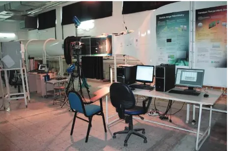
The experiments were performed in a low speed, suction type wind tunnel with a square working section of 500 mm x 500 mm at the laboratory located at the Department of Energy Systems Engineering, Erciyes University via Wind Engineering and Aerodynamics Research Group (WEAR) as shown in Figure 1. Turbulence intensity of the tunnel is 0.35% and the operating range of tunnel speed was 1-45 m / s [7, 17]. The experiments were conducted at Reynolds numbers of 25000, 50000 and 75000.
Figure 1.The experimental set-up and the wind tunnel.
A two-dimensional NACA4412 airfoil was produced via 3D printer as shown at Figure 2. After the two-dimensional NACA4412 airfoil was manufactured with 3D printer, it was rubbed with sandpaper to ensure smoothness of the surface and two plexiglas were used. The airfoil model has a chord (c) of 10 cm and a span of 10 cm.
Figure 2. NACA4412 airfoil model produced via 3D printer.
2.2 Determination of the aerodynamic force coefficient for two-dimensional NACA4412 airfoil
To find out the aerodynamic force coefficients for two-dimensional NACA4412 airfoil, a computer-controlled automatic angle-changing force measurement system was used as demonstrated in Figure 3. Lift and drag forces were separately measured by strain-gauge. Then, these forces were converted to drag coefficient (CD) and lift coefficient (CL) where placed x-axis and
y-axis at the coordinate system, respectively.
Figure 3. Automatic computer controlled force measurement system.
Figure 4 shows the experimental results of force measurements at Reynolds number of 25000. The stall angle is 12° and the maximum lift coefficient (CL,max) is
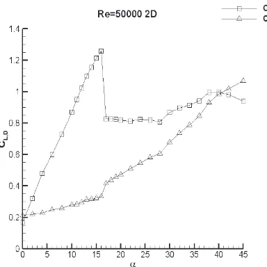
0.9. The drag coefficient increased as angle of attack increased gradually. This situation for Reynolds number of 50000 is illustrated in Figure 5. The stall angle is 16° and the maximum lift coefficient is 1.25. It is seen that the swift climbing at the drag coefficient after the stall angle. The stall angle is 18° and the maximum lift coefficient is 1.35 for Reynolds number of 75000 as shown in Figure 6. The lift and drag coefficient increased dramatically until the stall was occurred. From these figures, it was concluded that as Re number increased, the stall angle increased.
Figure 5.Aerodynamic force coefficients at Reynolds number of 50000 for NACA4412 airfoil.
Figure 6.Aerodynamic force coefficients at Reynolds number of 75000 for NACA4412 airfoil.
2.3 Flow Visualization with smoke-wire experiment for NACA4412 airfoil model
Flow visualization with smoke-wire is an easier way in order to evaluate the structure of flow over the airfoil
.
The method consists of a slim wire positioned in the flow field of experiment chamber. The wire was located in front of leading-edge of airfoil. The vertical location of the wire was manually adjusted for proper positioning of the sheet of smoke. The small drops of the oil were gradually drained from the top of the wire by means of syringe. The electrical current was used through the wire in order to heat. The wire was heated as the small drops of the oil were drained. A compact camera was also used in order to visualize the sheets of smoke. It was almost positioned 50 cm forward of the experiment chamber and was focused to the airfoil. 30 frames were recorded at each Reynolds number. Two or three of fine frames were chosen and the corresponding flow structures were observed as demonstrated at Figure 7, Figure 8 and Figure 9, respectively.a) 8°
b) 12°
Figure 7. Flow visualization with smoke-wire experiments at Reynolds number of 25000.
The laminar separation bubble is seen clearly at Reynolds number of 25000 as shown in Figure 7(a). The separation bubble moved towards leading edge over the airfoil when the angle of attack increased from 8to 12. For Reynolds number of 50000, the leading edge flow separation happens at 16 even though the laminar separation bubble is observed at 12 as demonstrated in Figure 8(a) and 8(b), respectively. The flow separation can also observe at Reynolds number of 75000 as shown in Figure 9(b). Yet, the angle of the flow separation is 19 and the leading-edge separation is also seen at 19.
a) 12°
b) 16°
a) 18°
b) 19°
Figure 9. Flow visualization with smoke-wire experiments at Reynolds number of 75000.
2.4 Hot wire anemometry system
The hot wire system used in this experiment is a single sensor miniature wire probe. The miniature wire probe has a 5m diameter, 1.25 mm long platinum-plated tungsten wire sensor. The system has the ability to measure one dimensional flows of low turbulence intensity. In velocity measurement experiments, the sample rate was 2 kHz and 20000 data was obtained for each experiment. DANTEC DYNAMICS mini-CTA software is used for the velocity measurement from 1C, which means 1 chord length of airfoil, forward of the trailing-edge of airfoil.
Figure 10. Hot-wire probe [18]
The hot wire probe needs to be calibrated before being used in the experiment. There is a relationship between the flow velocity and the measured voltages recorded the hot-wire anemometry system for hot-wire process. The traverse running both vertically and horizontally is conducted to move the hot-wire probe.
2.4.2 Hot wire anemometry data acquisition and analysis
Once the velocity calibration is completed, the hot wire probe is positioned 1C forward of trailing-edge of
airfoil at the wake region of the airfoil. 2 cm above of the airfoil is chosen as starting point for measurement and the hot wire runs along the y-axis at the wake region of the airfoil. The hot wire continues to measure until 2 cm bottom of the airfoil. After the hot wire experiments are completed, the value of U/U at the wake region is
obtained at Reynolds number of 25000, 50000 and 75000 as shown in Figure 10, respectively. At Reynolds number of 25000, the velocity at the wake region decreased from 1.034 to 0.6 at 16 . The velocity similarly decreased from 1.074 to 0.37 at 20 . The similar decreasing is observed at Reynolds number of 50000 and 75000. After the flow separates from the surface of airfoil, it meets with the flow coming from the bottom of the airfoil at the wake region. For the separated flow over the airfoil is more dominant than the flow at the bottom of airfoil, velocity decreasing happens at the wake region. The flow separation moves to leading-edge of the airfoil when the angle of attack increases. The separated flow is more powerful than the separated flow at the former angle of attack. Thus, the velocity decreasing at the wake region increase dramatically when angle of attack increases as illustrated at figure 11.
Re = 25000 Re = 25000
Re = 50000 Re = 50000
Re = 75000 Re = 75000
Figure 11. The value of U / U at the wake region of NACA4412 airfoil
&RQFOXVLRQ
experiments were carried out on an NACA4412 airfoil at Reynolds number of 25000, 50000 and 75000 where the leading-edge separation exists. The lift coefficient (CL)
increases gradually when the angle of attack increases at Reynolds number of 25000. Drag coefficient (CD) also
increases but there is no rapid climbing. The lift and drag coefficients also increase clearly at Reynolds number of 50000 and 75000 when the angle of attack increases. Unlike Reynolds number of 25000, there is a sudden climbing for the drag coefficient. The stall occurs at 16, 19 at Reynolds number of 50000, 75000, respectively. An abrupt stall can be observed at Reynolds number of 50000 and 75000 whereas mild stall can be observed at Reynolds number of 25000. It is concluded that the stall angle increase when Reynolds number increase. Beside, the smoke-wire experiments at Reynolds number of 50000 and 75000 show a fine coherence with the aerodynamic force coefficient experiments. The velocity at the wake region of the airfoil decreased when angle of attack increased. It means that the flow separation headed to the leading-edge of the airfoil gradually when angle of attack increased.
$FNQRZOHGJPHQWV
The authors would like to acknowledge funding from the Scientific and Technological Research Council of Turkey (TÜBTAK) under the project no: 213M329.
5HIHUHQFHV
1. S.J. Schreck, N.N. Sørensen, M.C. Robinson, Aerodynamic structures and processes in rotationally augmented flow fields. Wind Energy, 10(2), 159-178 (2007)
2. M.S. Genc, U. Kaynak, H. Yapc, Performance of transition model for predicting low Re aerofoil flows without/with single and simultaneous blowing and suction. Eur J Mech B-Fluid.30(2), 218-235 (2011) 3. M.S. Genc, I. Karasu, H.H. Ackel, M.T. Akpolat, Low Reynolds number flows and transition, in: M. Serdar Genc (Ed.), Low Reynolds Number Aerodynamics and Transition, Intech-Sciyo Publishing, ISBN 979-953-307-627-9 (2012)
4. M.S. Genc, U. Kaynak, G.D. Lock, Flow over an Aerofoil without and with Leading Edge Slat at a Transitional Reynolds Number. Proc IMechE, Part G: J Aerospace Eng. 223(3), 217-231 (2009)
5. M.S. Genç, Unsteady aerodynamics and flow-induced vibrations of a low aspect ratio rectangular membrane wing with excess length. Exp. Therm Fluid Sci. 44, 749-759 (2013)
6. P. Rojratsirikul, M.S. Genc, Z. Wang, I. Gursul, Flow-induced vibrations of low aspect ratio rectangular membrane wings. J Fluid Struct. 27, 1296-1309 (2011)
7. M.S. Genc, I. Karasu, H.H. Ackel, An experimental study on aerodynamics of NACA2415 aerofoil at low Re numbers. Exp Therm Fluid Sci. 39, 252-264 (2012)
8. I. Karasu, M. S. Genç, H. H. Açikel, Numerical study on low Reynolds number flows over an Aerofoil. J. Appl. Mech. Eng. 2, 131 (2013)
9. M.S. Genc, Numerical Simulation of Flow over a Thin Aerofoil at High Re Number using a Transition Model. Proc IMechE, Part C-J Mech Eng Sci, 224(10), 2155-2164 (2010)
10. White F.M. Fluid Mechanics, McGraw-Hill, Inc.4th edition (2004)
11. Schlicting H. Boundary Layer Theory. McGraw-Hill,Inc. /th edition (1979)
12. J. Ketz, A. Plotkin, Low-speed aerodynamics: from wing theory to panel methods. McGraw-Hill, Incorporated (1991)
13. B.H. Carmichael, Low Reynolds number airfoil survey. National Aeronautics and Space Administration, Langley Research Center (1981)
14. R. Wahidi, W. Lai, J.P. Hubner, A. Lang. Volumetric three-component velocimetry and PIV measurements of Laminar Separation Bubbles on a NACA4412 Airfoil. 16th Int. Symp of Applications of Laser Techniques of Fluid Mechanics. Lisbon, Portugal. 09-12 July, (2012)
15. M. O'meara, T.J. Mueller, Laminar separation bubble characteristics on an airfoil at low Reynolds numbers. AIAA journal,25(8), 1033-1041 (1987)
16. M. Agrawal, G. Saxena, Analysis of wings using airfoil NACA4412 at different angle of attack. IJMER.3, 1467-1469 (2013)
17. I. Karasu, Experimental and numerical investigations of transition to turbulence and laminar separation bubble over aerofoil at low Reynolds number flows. Graduate School of Natural and Applied Sciences, Erciyes University, Kayseri, Turkey (2011)