Available online: https://edupediapublications.org/journals/index.php/IJR P a g e | 4 3 8 8
S. Steeven
M.Tech, Electrical Power Systems
Talla Padmavathi College Of Engineering,Kazipet,Warangal
V. Prakash
Associate Professor,EEE
Talla Padmavathi College Of Engineering, Kazipet,Warangal
Abstract:The main objective of this project is to discuss the design and implementation of a multi-agent system that providesintelligence to a distributed smart grid because of their benefits of extensibility, autonomy, reduced maintenance, etc. In the literaturethe smooth operation of a power system requires a control architecture that consists of hardware and software protocols for exchangingsystem status and control signals. This project presents the modeling of intelligent energy control center (ECC) controlling DistributedEnergy Resources (DERs) using a multi-agent system. The multi-agent system consist of smart grid and agents such as user agent,distributed energy resources (DER) agent , database agent, control agent, work in collaboration to perform assigned tasks. The DERmodel is created on the client side and ECC is created on the server side.
Keywords-Distributed energy resources (DER) and internet protocol (IP), distributed generators (DGs), energy control center (ECC),Artificial Neuro Fuzzy Interface System (ANFSI.
I. INTRODUCTION
Multi-Agent systems (MAS) consist of multipleintelligent agents that interact to solve problems thatmay be beyond the capabilities of a single agent orsystem. For many years, conceptual MAS designsand architectures have been proposed for applicationsin power systems and power engineering. With theincreasing use and modeling of distributed energyresources for microgrid applications, MAS are wellsuited to manage the size and complexity of theseenergy systems.
The successful operation of a power system dependslargely on its ability to economically and
reliablymeet load demands of residential, commercial andindustrial customers. Early power utilities employedhuman dispatch operators equipped with SupervisoryControl and Data Acquisition (SCADA) systems tomanage plant control, protective relaying,transmission switching and communication protocols,along with economic operation of largeinterconnected power plants. While SCADA systemsoffer timely and detailed monitoring of traditionalgrid resources, the raw data generated often containsonly implicit informationAutonomous control of power system operationsusing Multi-Agent Systems (MAS) has shown toovercome many such limitations. MAS are composedof multiple intelligent agents that interact to solveproblems that may be beyond the capabilities of eachindividual agent. In recent years, MAS have beenemployed in a wide range of power systemapplications including modeling of electricitymarkets, grid protection, fault restoration and gridcontrol. In 2007, a comprehensive review of MAS forpower engineering applications was conducted by theIEEE Power Engineering MAS working groupregarding the technologies, standards and tools forbuilding MAS and concepts, approaches andtechnical challenges within the field of MAS that areappropriate to power engineering applications.
Recently however, technological
advancements,security concerns, regulatory policy andenvironmental considerations are changing thelandscape of electricity generation and transmissionby reducing the grid’s reliance on large centralizedgeneration facilities. Significant changes toderegulation and competition in the electrical
Design of Energy Control Center for Distributed
Available online: https://edupediapublications.org/journals/index.php/IJR P a g e | 4 3 8 9
industryover the past two decades led to the emergence ofwholesale energy markets reliant on the decentralizeddecisions of generation firms in contrast to utilitybased centralized generation units. Consumer demandfor clean energy and government regulation is drivingthe increasing proliferation of Distributed EnergyResources (DERs) like photovoltaics (PV), fuel cells,solar and wind power into the modern electric grid.Microgrids have emerged as an effective paradigm tomanage DERs. A microgrid is an integrated energysystem consisting of interconnected loads anddistributed energy resources that operates in parallelwith the primary power grid, or in a standalone“islanded” mode.In the event of a failure, the generation andcorresponding loads of the microgrid can be isolatedfrom the distribution system without harming theintegrity of the transmission infrastructure.
Microgrids help facilitate rapid integration of DERs,offering “plug and play” capabilities withoutrequiring the re-engineering of the distribution systemcontrol architecture. Microgrids are seen as a futurepower system configuration providing clear economicand environmental benefits. Extensive efforts are inprogress across the world to demonstrate microgridoperating concepts in laboratories and in pilotnstallations. In America alone, the Department ofEnergy is expected to oversee the development ofcommercial scale microgrid systems capable ofreducing outage time of required loads by over 98%at a cost comparable to non-integrated baselinesolutions while reducing emissions by at least 20%and improving energy efficiencies by more than 20%.
In the past few years, multi-agent techniques have foundtheir place in many distributed systems such as distributedproblem solving, distributed information fusion, distributedscientific computing, and also DER management.However, these earlier applications, especially in the area ofpower, tended to neglect the size of the application domainwhile focusing only on functional properties like agentnegotiation, collaboration, and communication. In the contextof the electric power industry, the scale of the power systemcan be anywhere from thousands to tens of
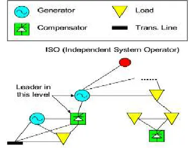
thousands of nodeswith an array of interconnections between the nodes.Therefore, in order to translate multi-agent techniques topractical systems, scalability issues become significant. Thescalability of a multi-agent system depends on whether theworst-case performance of the system is bounded by a polynomial function of the load. A dynamic hybrid multiagent system is proposed in this paper as a means to achievescalability. In this hybrid architecture, besides connecting totheir parents and children, each agent can also connect to theirsiblings. Peer agents can communicate and collaborate witheach other. Peer agents will dynamically select a leader toestablish the real connection with their parents. The hybridstructure is illustrated in Fig. 1.
Fig. 1. Hybrid multi-agent architecture for scalability
Available online: https://edupediapublications.org/journals/index.php/IJR P a g e | 4 3 9 0
Fig 2. Two-bus system with reactive power compensator at midpoint
II. BLOCK DIA GRA M OF THE
SIM ULA TION M ODE
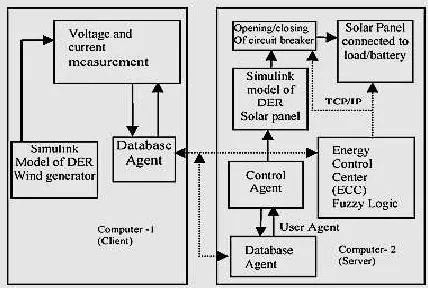
The block diagram of the multi-agent system simulationmodel is given in Fig. 3. Wind power generation consists ofa wind mill, induction generator connected to the gridthrough circuit breaker and the load. Solar power generationconsists of solar panel, inverter, transformer connected to theload and circuit breaker. The interconnection of wind power,solar power and grid forms the power system smart grid withDER. The voltage measured in wind power generator andsolar power generator is sent to ECC through the Internet.The Artificial Neuro Fuzzy Interface (ANFIS) present inECC activates the circuit breaker according to the voltagerequirement. The addition/removal of solar panels to the gridis controlled by ANFIS. If solar panel is removed from thegrid, it will be connected to charge the battery. Since ANFISis used for the control, it can be extended to control circuitbreaker (CB-1) and circuit breaker (CB-2), as given in Fig.3, depending upon the availability of DERs.
Fig.3: Block diagram of power system interconnectedwith wind and solar power generation
scheme
In this work, simulation model of wind power generator iscreated in computer-1 as shown in Fig. 4. It is considered asclient. The voltage, current, frequency and power of DERcan be measured. This is known as DER agent. It isconverted in to excel sheet using MATLAB commandswhich is called data-base agent.
Fig.4: Representation of multi-agent system
Available online: https://edupediapublications.org/journals/index.php/IJR P a g e | 4 3 9 1
The circuit breaker (CB-1) is connecting wind powergeneration to grid. The circuit breaker (CB-2) is connectingsolar power generation to grid. To utilize the maximumpower from solar panel, switch is used to connect the solarpower to local load or charging the battery as shown in Fig.3.
A. Des ig n o f A NFIS
ANFIS is a simple data learning technique that uses a fuzzyinference system model to transform a given input into atarget output. This prediction involves membershipfunctions, fuzzy logic operators and if – then rules. There aretwo types of fuzzy system, commonly known as theMamdani and Sugeno models. There are five mainprocessing stages in the ANFIS operation, including inputfuzzification, application of fuzzy operators, applicationmethod, output aggregation and de-fuzzification.
A NFIS A rch itectu re : Generally, ANFIS is a multilayer feed forward network inwhich each node performs a particular function (nodefunction) on incoming signals. For simplicity, we considertwo inputs 'x' and 'y' and one output 'z '. Suppose that therule base contains two fuzzy if-then rules of Takagi andSugeno type
Ru le 1: IF x is A1 and y is B1 THEN f1=P1x+Q1y+R1
Ru le 2: IF x is A2 and y is B2 THEN f2=P2x+Q2y+R2
The ANFIS architecture is a five layer feed forward networkis given as
Lay er 1: Every node in this layer is a square node with anode function (the membership value of the premise part)
Oi=µAi(X)
Where, x is the input to the node i , and Ai is the linguisticlabel associated with this node function.
Lay er 2: Every node in this layer is a circle node labeledwhich multiplies the incoming signals. Each node outputrepresents the firing strength of a rule.
Oi2=µAi(X) µBi(Y) where i = 1:2
Lay er 3: Every node in this layer is a circle node labeled N(normalization). The ith node calculates the ratio of the ithrule’s firing strength to the sum of all firing strengths.
Oi3=W= w1/(w1 + w2) , where i = 1:2
Lay er 4: Every node in this layer is a square node with anode function
Oi4=W (PiX+QiY+Ri)
Lay er 5: The single node in this layer is a circle nodelabeled that computes the overall output as the summation ofall incoming signalsOi5 = System output, where i = 1:2
B. A NFIS Learn in g A lg o rith m
The ANFIS Learning Algorithm uses a two-pass learningcycle. In the forward pass, S1 is unmodified and S2 iscomputed using a Least Squared Error (LSE) algorithm(Off-line Learning). In the Backward pass, S2 is unmodifiedand S1 is computed using a gradient descent algorithm(usually Back Propagation). From the ANFIS structureshown in Figure5, it has been observed that when the valuesof the premise parameters are fixed, the overall output canbe expressed as a linear combination of the consequentparameters.
Fig.5: ANFIS Structure formation
Available online: https://edupediapublications.org/journals/index.php/IJR P a g e | 4 3 9 2
pass. In the forward pass of thehybrid learning algorithm, functional signals go forward upto layer 4 and the consequent parameters are identified bythe least squares estimate. The back propagation is used toidentify the nonlinear parameters (premise parameters) ) andthe least square is used for the linear parameters in theconsequent parts.
III. SIM ULA TION M ODEL OF THE M ULTI-A GENT SYSTEM
The Fig.6.Indicates the simulation of ECC with ANFIS, if itis created in computer 3. The output of ANFIS is used tocontrol the solar panel. Before simulation, the excel files areconverted into database agent in MATLAB commandwindow and loaded to the workspace. Based on themagnitude of voltage received in the inputs, the decision istaken by the ANFIS. The output of ANFIS is constant value(1, 2, 3, 4, and 5) and this is used to drive the multi portswitch. Based on the output of ANFIS, the number of panelsare added or removed in the model. The wind powergeneration, solar power generation and grid are connectedthrough the circuit breakers (CB-1) and (CB-2) as shown inFig.3.These breakers are activated based on the step pulse.In this work, these circuit breakers are controlled by ECCcommand. The ECC is enabled to monitor the solar voltageand wind voltage magnitude for regular intervals of time tomake the decision on number of solar panels connected tothe load/grid or battery based on ANFIS output.. Duringsimulation of model shown in Fig. 6, the voltage induced insolar panel and wind generators are stored in .mat file and itis converted into excel format using MATLAB commands.
A . So lar Po wer Gen eratio n
In a typical solar PV module, 36 cells are connected togetherin series. In each module, the voltages induced in the 36cells are added together. Series combination of 36 cells willprovide 21.6 V. To generate 230 V ac supply with 50 Hz,approximately 11 modules are connected. To convert DC toAC, inverter is used and to increase the voltage, transformeris used. Solar power generation consists
of solar panel,inverter, trans-former connected to the load and circuitbreaker.
B. W in d Po wer Gen eratio n
Self excited wind power generation scheme is used in thiswork. Induction generator connected in parallel withcapacitor bank provides excitation to the generator. When itis connected with grid, it injects power depending upon thespeed of the generator. The speed of the generator dependsupon the wind speed. Wind power generation consists of awind mill, induction generator connected to the grid throughcircuit breaker and load.
Fig.6: Simulation diagram of power system interconnected with wind and solar power generation
scheme
IV. SIM ULA TION RESULTS
Available online: https://edupediapublications.org/journals/index.php/IJR P a g e | 4 3 9 3
V. CONCLUSION
The simulation model of ECC, with ANFIS controlling thesolar and wind power generation interconnected with gridusing multi-agent system is described in this project. Thevoltage of wind and solar power are stored in a excel sheetas a database agent. ANFIS controls the switch provided inthe solar panel to add/remove depending upon the voltagerequirements. The results prove that the frequency fluctuations are reduced.The wind power generator and the solar powerconnected with local load and battery and the ECCcontrolled by Artificial Neuro Fuzzy Interface System(ANFSI) is used in PV system for reducing the transmissionand distribution losses, complexity and THD and increasesefficiency.
REFERENCES
[1] H. Rongxian, L. Zhiwen, C. Yaoming, W. Fu, and R.Guoguang, “DC micro-grid simulation test platform,” inProc. 9thTaiwan Power Electron. Conf., 2010, pp.1361–1366.
[2] S. Morozumi, “Micro-grid demonstration projects inJapan,” in Proc. IEEE Power Convers. Conf., Apr.2007, pp. 635–642.
[3] Y. Uno, G. Fujita, R. Yokoyama, M. Matubara, T.Toyoshima, and T. Tsukui, “Evaluation of micro-gridsupply and demand stability for differentinterconnections,” in Proc. Power Energy Conf., 2006,pp. 611– 616.
[4] Experience in Developing and Promoting 400 V DCDatacenter Power, T. V. Aldridge, Director, EnergySystems Research Lab, Intel Corporate TechnologyGroup, Green Building Power Forum, Jun. 2009.
[5] MaximizingOverall Energy Efficiency in Data Centres,S. Lidstrom, CTO, Netpower Labs AB, Green BuildingPower Forum, Jun. 2009.
[6] Renewable Energy & Data Centers, J. Pouchet, DirectorEnergy Initiatives, Emerson Network Power., GreenBuilding Power Forum, Jun. 2009.
[7] Development of Higher Voltage Direct Current PowerFeeding System in Data Centers, K. Asakura, NTTEnergy/Environment, Green Building Power Forum, Dec. 2010.
[8] Specifications for 400 V DC Power Supplies andFacility Equipment, D. Symanski, Sr. ProgramManager, Electric Power Research Institute, KeiichiHirose, NTT Facilities, and Brian Fortenberry, ProgramManager, Electric Power Research Institute, GreenBuilding Power Forum, Jan. 2010.
[9] Development of a DC Power Inlet Connector for 400 VDC IT Equipment, B. Davies, Director of Engineering,Anderson Power Products, Inc. Green Building PowerForum, Jan. 2011
[10] O. Castillo and P. melin, Studies in Fuzziness and SoftComputing Type2 Fuzzy Logic : Theory andApplications. New York, NY, USA: Springer-Verlag,2008.
A u th o rs :