VerMI: Verification Tool
for Masked Implementations
Victor Arribas1,
Svetla Nikova2, and Vincent Rijmen2
1
KU Leuven, imec-COSIC, Belgium,[email protected]
2
KU Leuven, imec-COSIC, Belgium,[email protected]
Abstract. Masking is a widely used countermeasure against Side-Channel Attacks (SCA), but the implementation of these countermeasures is chal-lenging. Experimental security evaluation requires special equipment, a considerable amount of time and extensive technical knowledge. So, to automate and to speed up this process, a formal verification can be per-formed to asses the security of a design. Multiple theoretical approaches and verification tools have been proposed in the literature. The majority of them are tailored for software implementations, not applicable to hardware since they do not take into account glitches. Existing hardware verification tools are limited either to combinational logic or to small designs due to the computational resources needed.
In this work we present VerMI, a verification tool in the form of a logic simulator that checks the properties defined in Threshold Implementations to address the security of a hardware implementation for meaningful orders of security. The tool is designed so that any masking scheme can be evaluated. It accepts combinational and sequential logic and is able to analyze an entire cipher in short time. With the tool we have managed to spot a flaw in the round-basedKeccakimplementation by Grosset al., published in DSD 2017.
Keywords: VerMI, Masking, Formal Verification, Non-completeness, Uniformity, Glitches, Logic Simulator
1
Introduction
derivex. Threshold Implementations has been proposed in [25] by defining the following three properties to secure a hardware design:
– Correctness: a shared function f such thatfi(x) =yi, wherei= 1, . . . , s, is correctly shared ifPy
i=y=f(x).
– Non-completeness: a shared functionf isdth-order non-complete if any combi-nation of up todcomponent functionsfi is independent of at least one input share.
– Uniformity: the outputs of a shared function have to conform a uniform distribution. Note that given a uniform sharing, it is sufficient to preserve the uniformity across operations to achieve univariate security (together with non-completeness).
Checking if a cryptographic implementation is in fact secure is a very demanding exercise. One way is by using attack based evaluations, but this is highly inefficient, since it requires a considerable effort implementing different attacks, ensuring solely security against those specific attacks. Following the same principle is the non-specific test vector leakage assessment (TVLA) [12] over the power consumption or the electromagnetic radiation of the device to detect leakage. Despite a few limitations [29], this method provides a more generic conclusion on the security and has been widely used in the literature [11, 22] to assess security of several implementations. Yet, TVLA and attack based evaluations need the actual ASIC or a correctly programmed FPGA, as well as special equipment to be performed. Formal verification is another way of evaluating the security of a cryptographic implementation. This method studies the theoretical conditions for a design to be secure [2, 3, 5, 10, 13] or models the implementation to simulate its behavior [7, 26].
Our contribution. We propose a Verification Tool to aid in the design flow towards secure hardware implementations. The tool helps to spot any mistake in the application of the aforementioned properties with bit precision and provides an initial univariate security evaluation without any special equipment. In addition, the tool is applicable to the CMS [27] and DOM [17] masking schemes, since they inherit the aforementioned TI properties. VerMI works at both algorithmic and implementation level, with an inherent capability to check designs in the presence of glitches. We build a structural model of the circuit, providing highly precise information on the behavior of every bit. When analyzing the first-order DOM
KeccakS-box, our program takes 1.34ms to check non-completeness and 1.7s to
check uniformity. Thus, the total time needed for a complete analysis is less than 2s on an Intel Core i5-4590 CPU with a clock frequency of 3.3GHz and 7.6 GB of RAM running a 64-bit Linux CentOS7.
the round-basedKeccakimplementation in [18], which fails the non-completeness property.
2
Previous work
Formal verification for masked implementations is a widely researched topic [2, 4, 13, 15, 16, 23]. These works target software implementations and neither of them take into account glitches. Therefore, they can not be applied to verify hardware implementations.
Formal verification of masked hardware implementations can be done in several stages of the design flow: at algorithmic, at implementation or at physical level. In the work of Reparaz [26] a tool for verification at algorithmic level is presented. The tool receives a software implementation of the secured function and performs a leakage assessment over simulated traces. However, glitches are not taken into account.
At implementation level Bertoniet al.in [7] present a tool suitable for hardware implementations in the presence of glitches. Nevertheless, their tool only analyzes combinational logic with a simple power model. Bloemet al.in their recent work [10] also present a formal verification method for hardware implementations in the presence of glitches. Given a hardware implementation they extract the netlist and model the logic gates using a Fourier expansion. Three different types of variables are defined, i.e. secret variables (S), masks (M) or other variable (P), and every intermediate value of the circuit islabeled with a set of these variables, where the labels are based on the Fourier representation of the Boolean function. A value is not secure if the associated label contains a set with only secret variables. To simulate glitches, the representation of a gate is extended to compute any Boolean function from its original inputs and to analyze higher-orders, a SAT solver is instantiated; both cases increase the analysis complexity considerably. Looking at their analysis of the first-order DOMKeccakS-box [18], it is possible to see how much the run time increases when performing the analysis considering glitches versus not considering them, taking 20s in the first case and around 1s in the second case. Results in [10] are gathered on an Intel Xeon E-52699v4 CPU with a clock frequency of 3.6 GHz and 512 GB of RAM running a 64-bit Linux Debian 9.
3
Design choices
VerMI is designed to parse a synthesized netlist, where a logic simulator reconstructs the logic circuit using wires, pins and gates as objects connected to one another. Thus, it is possible to simulate the functionality of the circuit and perform efficient tree search to check connections.
3.1 Building the netlist
take into account the different coding styles. In order to unify the files to analyze, the first step is to synthesize the design and extract the netlist. To do this, we use an RTL synthesis tool with open source NanGate libraries. The tool is currently programmed to parse components from this library, therefore restricted to netlists using gates with the same name. If needed, the code is easily adaptable to any other library.
The program parses the elementary gates of this library. To get a single netlist that uses solely these elements, we specify-ungroup allso that the netlist does not synthesize sub-modules and uses them to build the top module. This tool is meant to check security oriented implementations, so in order to avoid any optimization that might compromise the security, we also specify-exact map. This option specifies that the elements in the netlist exactly match the specifications in the HDL description. An implementation compiled without this option or with any optimization options could be classified as non-secure by the tool, not due to a designers fault, but due to possible optimizations of important blocks for the security of the design.
3.2 Logic simulator
We create three classes that allow us to build the structural model of a given circuit. These objects are the basic logic elements:
Wire. A wire needs, basically, to hold a name and a value. This first class includes several attributes: the name of the wire, the value, and a flag to note that the wire is already evaluated conform the attributes. It includes a single method,eval wire, which evaluates the value of the wire, sets the flag to evaluated and propagates the simulation to the next gate (more details given in Section 4.3).
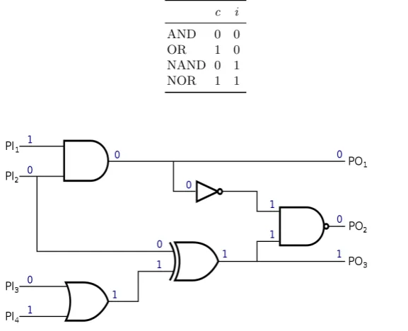
Gate. A gate requires, primarily, a type and a functionality. This class keeps the type of gate (AND, XOR, MUX), the name given to the instantiation of the block, and the functionality, a function that evaluates the output according to the type of gate, no matter what type. Certain gates also include the so-calledcontrolling value candinversion i [21]. An input value is said to be controlling if it determines the value of the output regardless of the value of the other inputs. Inversion determines whether the output value is inverted. By definition, only the four basic gates AND, OR, NAND, and NOR have these values, given in Table 1:
Pin. The third class is created to connect the previous two. The presence of this union is important, since it determines the role of each wire when evaluating a gate. It stores the name of the pin, used later when computing a gate function, and the wire and the gate to which the pin is connected.
Connecting elements. For each wire, gate and pin, the tool instantiates a new pointer to the specific object. Classwirehas two pointers to pin,pin fromand
Table 1: Controlling and inversion values for basic gates
c i
AND 0 0 OR 1 0 NAND 0 1 NOR 1 1
Fig. 1: Circuit structural model and logic simulator
Pins are also important to manage fan-outs. In digital logic, fan-outs occur when a logic gate output is fed into multiple subsequent gates as input. We model them by adding two more attributes to the wire class: the first one, a flag to indicate whether certain wire has a fan-out, and the second one, a vector of pins to keep the multiple endings of this wire,fan out pins. These new pins represent the fan-out wires that are driven to the different gates.
3.3 Header
4
VerMI
To initiate the program, we need to provide the source path for the RTL synthesizer and create few directories to store the netlist and some other files. First, the program analyzes the input file, from which the language, the header information and the name of the top module are retrieved. Then, it generates a specific.tcl file for this module and calls the RTL compiler to source it. Finally, the netlist is generated and wires, pins and gates are created to build the circuit model.
Once this is done the tool offers several functionalities: to calculate all input dependencies of the output variables, to check non-completeness and uniformity.
4.1 Input dependencies
This feature outputs the number and the specific input variables on which the outputs depend.
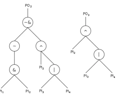
Recursive tree search. Taking advantage of the objects mentioned above, we are able to build a detailed structural model of the circuit and hence perform a highly efficient tree search to get all input dependencies. Logic circuits have a hierarchical tree structure, where the root nodes correspond to the primary outputs, i.e outputs of the module. The subtrees’ parent nodes correspond to the output of a gate and the children to its inputs.
We implement a recursive algorithm that starts at a primary output and goes through the circuit backwards covering all paths containing this output. The algorithm keeps running until it arrives to a primary input, which is saved as a dependency if it is declared as sensitive in the header. Alg. 1 presents the pseudo-code of this function and Fig. 2 illustrates the corresponding tree for two outputs of the circuit shown in Fig. 1:
Algorithm 1Recursive Tree Search algorithm
1: proceduresearch back(gateg, wiresw) 2: for allinputsiingdo
3: if iis a Primary Inputthen
4: if iis not yet savedandiis sensitive datathen
5: w←i
6: end if
7: else
8: search back(g→i,w) Wheregis the gate drivingi
9: end if
10: end for 11: end procedure
4.2 Non-completeness
Fig. 2: Tree search in digital circuits
Decision algorithm. Once we have the dependencies of every output, we check whether all shares for the same variable are included. If this is the case, the variable fails non-completeness. The tool goes through every output performing this check. If any of them are failing, it saves this information in a text file that at the end contains the information of every output sensitive variable failing non-completeness. Finally, it announces whether this property is fulfilled or not.
To check whether all shares for the same variable are included is not a trivial task, since the tool is unable to distinguish between variables and shares. Taking advantage of the matrix data structure (See Sec. 3.3) built when parsing the netlist, the tool checks if the analyzed wire dependencies include all inputs from the same row. Hence, all shares of that variable are being used to compute certain output.
Single bit variables. Variables in a hardware module can be specified as a single bit, as collection of bits (bus) or even with more complex data structures. In case a variable is declared as a bus, the program creates a different variable for each bit in the bus. Managing the entire bus would be faster, but also less detailed. Same procedure applies with different data structures. This way the VerMI tool’s results are given with bit precision.
This distinction is crucial to make the tool able to analyze masking schemes for which verification of the inputs independence is required [17, 27] as part of the non-completeness check. By performing the analysis bitwise it is possible to catch possible dependencies between bits introduced by intermediate operations.
dth-order non-completeness. All possible combinations of d outputs are
an-alyzed with the same method presented above. The difference now is that the dependencies of thedoutputs are combined and the tool looks among all of them. The output file includes all combination ofdoutput variables that together fail non-completeness.
Currently VerMI supports up to third-order non-completeness verification. However, it can be easily extended to support verification of any meaningful order.
4.3 Uniformity
The third functionality is to check whether uniformity is preserved across operations. The tool calculates the output distribution of a given module by simulating all possible inputs. The frequencies of occurrence of each output vector are calculated for the different input sharings. If all frequencies are the same inside every group of input sharings, then the module is said to preserve uniformity. To generate uniformity-preserving shares is easy for invertible linear operations, while for non-linear operations it is not, since interaction between shares is needed. This functionality is meant to analyze these functions separately and check whether they preserve uniformity.
Simulation. All possible input vectors to the circuits are generated and simulated one by one at generation time, so there is no need to store all of them. Every primary input is evaluated with the corresponding value of the bit string. The
wire class member functioneval wireis called to evaluate the wire and set it as evaluated. If a wire is already evaluated, the value does not change.
There are several levels of simulation depending on the level of modeling used to represent the simulated system. In our case we perform agate-level simulation, given the structural model of the circuit built by the tool. Taking advantage of this representation, it is possible to implement anevent-driven simulation, also known as activity-directed simulation. An event represents a change in the value of a signal, which at the same time activates the component driven by this wire [21]. The tool only evaluates active elements that may as well change their output value creating new events.
The simulation starts evaluating the primary inputs which activates the first gates and propagates the events, elements being evaluated in order of activation. A data structureevent listis created, where pending elements are waiting to be evaluated. An active component is evaluated only if all its inputs have already been evaluated, otherwise it is sent to the end of the queue following the already active elements. The functioneval wireis in charge of propagating the simulation, which continues until the event list is empty. When a wire is evaluated, all gates (including fan-outs,if exist) driven by this wire areactivated and stored inevent listvector for subsequent evaluation.
isc⊕i,candigiven in Tab. 1. In addition to set the value of the output, the rest of the inputs are fixed toevaluated with valuec⊕i. Possible fan-outs in the inputs of the element are not evaluated with this vale. By setting the rest of the inputs to
evaluated, the possibility of extra activations is avoided.
In order to be able to simulate the next test vector it is necessary to reset the current values. To do so, a function is called to set the value of all wires to “empty” and set it as not evaluated.
Evaluation. We use the formulas from [9] to evaluate the uniformity. We check whether, for certain unshared input, every output has the same frequency of occurrence when all possible sharings of this input are evaluated. This is repeated for every possible unshared input together with, if added, all random bits specified. A frequencies vector is initialized to store the frequencies of the outputs happening for the evaluated unshared input. The output of the circuit evaluated modulo the size of the frequencies vector corresponds to the index of the frequency to be increased by one. This is done on the fly so that we do not need to instantiate multiple vectors.
Limitations. It is important to note that the uniformity check is limited by the total number of input bits and random bits. As explained above, the program has to generate all possible inputs for the circuit and evaluate each of them to get the output. Naturally, it is feasible to check just relatively small gadgets for uniformity, for instance SBoxes. The designer needs to provide the tool the sub-module that implements the SBox.
So far the biggest design analyzed was a six shares second-orderKeccakSBox, which meant a generation and evaluation of 230test vectors and which took almost 2 days using the same platform used in Sec. 1.
5
Sequential circuits
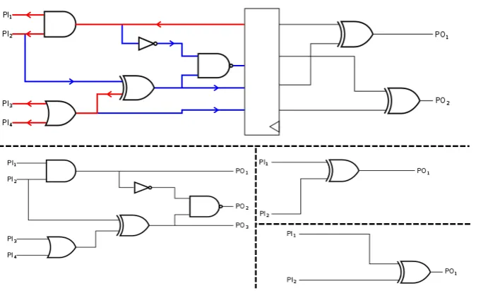
So far we have explained how the tool deals with combinational logic. In this section, we present how VerMI handles the presence of registers by dividing a big sequential circuit into all possible combinational sub-circuits or by simulating it altogether. This allows the program to analyze the security properties in the presence of sequential logic.
Fig. 3: Top: sequential circuit. Bottom: combinational sub-circuits for first and second stages.
5.1 Difficulties
At first sight, it is straightforward to split a sequential circuit. It is enough to get rid of the flip flops, their inputs being new primary outputs and their outputs new primary inputs. Then it is easy to decide which gates and wires belong to one or another circuit. The problem arises when a program needs to do this separation.
The tool stores a large amount of gates and wires that has to sort into the differ-ent sub-circuits. It is imperative to include the exact compondiffer-ents that correspond to a certain sub-circuit in order to perform an accurate analysis on the security afterwards. Missing an element or including extra components, would result in a possibly non-complete output that actually should have failed the test or, on the other hand, in extra dependencies that are not in the circuit, producing a false warning.
5.2 Back-and-forth algorithm
To do this “physical” separation in the simulated circuit, we design the Back-and-forthalgorithm and a new classsubcircuitthat includes all inputs, outputs, wires and gates of a sub-circuit. The algorithm works as follows:
2. Create a newsubcircuit, pick one of the outputs of this new vector, remove this wire from the new outputs vector, and perform abackwardstree search (depicted in red in Fig. 3) to find all the inputs. The algorithm will keep every
gate found in its passage through the circuit.
3. When a primary input is reached, it is stored (if it was not already) and then the algorithm calls a function to perform another tree searchf orward (blue) to find all the outputs that might depend on this input. When an output is reached, it is stored (if it was not already) and erased from the new outputs vector. If there is no fan-outs, no new output would be stored.
4. When the recursion is finished, the new sub-circuit is complete and it goes back to step two until the new outputs vector is empty.
Note that this algorithm may create independent sub-circuits from the same stage of a pipeline, even though visually they could be considered to belong to the same sub-circuit. This happens when there is not a fan-out that connects them together. In Fig. 3 the right sub-circuit would be divided in two by the tool, as it should be, since there is no connection whatsoever between the two of them. When analyzing higher-order non-completeness, independent sub-circuits from the same stage will be analyzed together.
Alg. 2 presents the pseudo-code for the above-presented algorithm. We use the notationw→g→v to refer to a gateg whose output isv and has an inputw. Similarly, we usew→g→vto refer to the outputv andw→g→v for the inputw.
5.3 Simulation
The simulation of registers is only needed for uniformity analysis, which is not affected by the fact that registers are memory or synchronization elements. Thus, the simulator ignores the concept of time and registers are treated as plain buffers.
6
Discussions
6.1 Fan-outs
It is important to take fan-outs into account and dedicate them special attention since their presence increases greatly the complexity of a digital circuit. The circuit is no longer a perfect tree: the nodes may have more than one parent. This results in multiple trees connected to each other. Thus, we design our Back-and-Forth
algorithm to fully cover all these connected trees.
6.2 Mapdata structure
When reading the netlist, the program first identifies inputs, outputs, and wires instantiating and initializing an object for each of them. Then the same is done to create all gates and pins. The problem comes when reading the file declaration, where the program gets a string and then it has to look for the correct objectwire
Algorithm 2RecursiveBack-and-forth algorithm
1: procedure subcircuit search back(wire w, subcircuit subcirc, wires remaining outs)
2: if wis a Primary Inputorwis a Flip-Flop outputthen 3: if wis not yet savedthen
4: subcirc.inputs←w
5: subcircuit search forth(w,subcirc,remaining outs) 6: else
7: for allinputsiingdo
8: subcircuit search back(i,subcirc,remaining outs)
9: end for
10: end procedure
11: procedure subcircuit search forth(wire w, subcircuit subcirc, wires remaining outs)
12: if wis a Primary Outputorwis a Flip-Flop inputthen 13: if wis not yet savedthen
14: subcirc.outputs←w
15: Erasewfromremaining outs
16: subcircuit search back(w,subcirc,remaining outs) 17: end if
18: if gt→w is not yet savedthensubcirc.gates←gt→w
19: if wbelongs to a fan-outthen
20: for allwiresf oemerging fromwdo
21: subcircuit search forth(f o,subcirc,remaining outs)
22: end for
23: end if 24: else
25: if w→gis not yet savedthen
26: subcirc.gates←w→g
27: end if
28: subcircuit search forth(w→g→v,subcirc,remaining outs)
29: if wbelongs to a fan-outthen
30: for allwiresf oemerging fromwdo
31: subcircuit search forth(f o,subcirc,remaining outs)
32: end for
correct object, which would happen several times for each component declaration, we build a Mapstructure withstring andwire types. Then using the member functionMap.find(“string”)we immediately get the corresponding object.
6.3 Software
The program is written in C++, which provides great performance and valuable high-level data structures. C++11 is needed to compile several containers from the STL libraries used in the code. For synthesis we use Synopsys Design Compiler Version I-2013.12 using the NanGate 45nm Open Cell library [24].
6.4 Computational complexity
Recursive algorithms. The algorithms used to calculate the input dependencies and to split the circuit into combinational sub-circuits have a time complexity of approximatelyO(log(N)),N being the number of gates in the circuit. Recursive algorithms might produce a stack overflow error if there are too many function calls to keep. This will mostly depend on the depth of the tree, which is directly related to the critical path of the circuit. It is highly improbable to find a circuit with such a critical path that would make the tool to consume such an amount of memory.
Non-completeness. The time complexity to evaluate this property scales propor-tionally with the number of output bits (No) and exponentially with the order of the analysis (d), following the expressionO(Nd
o).
Uniformity. The biggest problem to evaluate uniformity is that all possible inputs need to be evaluated to get all outputs frequencies of occurrence. Thus, the time complexity and the memory usage grow exponentially, following the expressions
O(2NiNs+Nr) and O(2No (Ns−1)
Ns ) respectively, whereNi is the number of input bits,
Nsthe number of shares andNr the number of random bits.
6.5 Register layers
For the tool to be able to analyze the non-completeness in a sequential circuits, the user has to specify in the header which register outputs are considered sensitive data and how shares and variables are distributed.
The synthesizer often optimizes the flip-flops output by using the inverted output, creating a new signal. This is an issue, since then the variables specified in the header would never be found. To prevent this the program includes in the.tcl
file the optionset dont touchfor the specified variables.
7
Evaluation
Non-completeness. Fig. 4 presents the time that the tool needs to evaluate first-, second- and third-order non-completeness for the full round of severalKeccak im-plementations with different number of shares to see the effect of the different number of outputs on the execution time:
Fig. 4: From left to right: first-, second- and third-order non-completeness evaluation, time versus number of output sensitive bits
As it can be seen, the higher the order of the analysis, the faster the time grows with the number of output bits.
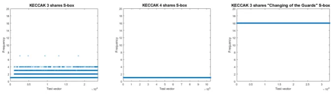
Uniformity. Fig. 5 shows the uniformity results for three different first-order
KeccakSBox implementations from [6, 8, 14]:
Fig. 5: Uniformity analysis on [6, 8, 14]
The conclusion from the analysis matches the theory from the aforementioned works. The first one is not uniform, as more than a single frequency can be appreciated. The second one achieves uniformity without any additional randomness with the frequency equal to 1, since the non-shared function is a permutation and so is the shared version. The last one, with the same number of shares as the first one, uses four bits of randomness uniformly distributing the output with frequency equal to 16.
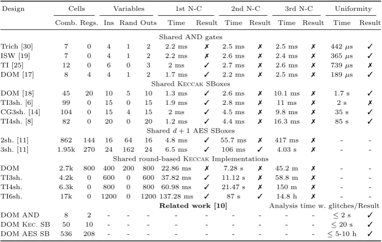
Table 2: Verification Tool benchmark
Design Cells Variables 1st N-C 2nd N-C 3rd N-C Uniformity
Comb. Regs. Ins Rand Outs Time Result Time Result Time Result Time Result
Shared AND gates
Trich [30] 7 0 4 1 2 2.2 ms 7 2.5 ms 7 2.5 ms 7 442µs 3
ISW [19] 7 0 4 1 2 2.2 ms 7 2.6 ms 7 2.4 ms 7 365µs 3
TI [25] 12 0 6 0 3 2 ms 3 2.7 ms 7 2.6 ms 7 739µs 7
DOM [17] 8 4 4 1 2 1.7 ms 3 2.2 ms 7 2.5 ms 7 189µs 3
SharedKeccakSBoxes
DOM [18] 45 20 10 5 10 1.3 ms 3 2.6 ms 7 10.1 ms 7 1.7 s 3
TI3sh. [6] 99 0 15 0 15 1.9 ms 3 2.8 ms 7 11 ms 7 2 s 7
CG3sh. [14] 104 0 15 4 15 2 ms 3 4.5 ms 7 9.8 ms 7 35 s 3
TI4sh. [8] 82 0 20 0 20 1.2 ms 3 4.4 ms 7 16.3 ms 7 85 s 3
Sharedd+ 1 AES SBoxes
2sh. [11] 862 144 16 64 16 4.8 ms 3 55.7 ms 7 417 ms 7 - -3sh. [11] 1.95k 270 24 162 24 6.5 ms 3 106 ms 3 4.03 s 7 -
-Shared round-basedKeccakImplementations
DOM 2.7k 800 400 200 800 22.86 ms 7 7.28 s 7 45.2 m 7 - -TI3sh. 4.2k 0 600 0 600 37.82 ms 3 11.12 s 7 58.8 m 7 -
-TI4sh. 6.3k 0 800 0 800 60.98 ms 3 21.47 s 7 150 m 7 -
-TI6sh. 17k 0 1200 0 1200 137.28 ms 3 87 s 3 14.8 h 7 -
-Related work [10] Analysis time w. glitches/Result
DOM AND 8 2 - - - ≤2 s 3
DOMKec.SB 50 10 - - - ≤20 s 3
DOM AES SB 536 208 - - - ≤5-10 h 3
Contrary to [10], VerMI is limited to univariate analysis. However, this results in considerably improved performance, which allows the verification of complex designs and complete ciphers, while [10] is limited by the inner complexity. The possibility to check non-completeness on a whole cipher led us to find a flaw in the round-basedKeccakimplementation from [18].
8
Conclusions
References
1. V. Arribas, B. Bilgin, G. Petrides, S. Nikova, and V. Rijmen. Rhythmic Keccak: SCA Security and Low Latency in HW. Cryptology ePrint Archive, Report 2017/1193, 2017. https://eprint.iacr.org/2017/1193.
2. G. Barthe, S. Bela¨ıd, F. Dupressoir, P. Fouque, B. Gr´egoire, and P. Strub. Verified Proofs of Higher-Order Masking, pages 457–485. Springer Berlin Heidelberg, Berlin, Heidelberg, 2015.
3. G. Barthe, S. Bela¨ıd, F. Dupressoir, P. Fouque, B. Gr´egoire, P. Strub, and R. Zucchini. Strong non-interference and type-directed higher-order masking. InProceedings of the 2016 ACM SIGSAC Conference on Computer and Communications Security, CCS ’16, pages 116–129, New York, NY, USA, 2016. ACM.
4. A. G. Bayrak, F. Regazzoni, D. Novo, and P. Ienne.Sleuth: Automated Verification of Software Power Analysis Countermeasures, pages 293–310. Springer Berlin Heidelberg, Berlin, Heidelberg, 2013.
5. S. Bela¨ıd, F. Benhamouda, A. Passel`egue, E. Prouff, A. Thillard, and D. Vergnaud. Randomness Complexity of Private Circuits for Multiplication, pages 616–648. Springer Berlin Heidelberg, Berlin, Heidelberg, 2016.
6. G. Bertoni, J. Daemen, M. Peeters, and G. V. Assche. Building power analysis resistant implementations of Keccak. Second SHA-3 candidate conference, August 2010.
7. G. Bertoni and M. Martinoli. A methodology for the characterisation of leakages in combinatorial logic. InSecurity, Privacy, and Applied Cryptography Engineering -6th International Conference, SPACE 2016, Hyderabad, India, December 14-18, 2016, Proceedings, pages 363–382, 2016.
8. B. Bilgin, J. Daemen, V. Nikov, S. Nikova, V. Rijmen, and G. V. Assche. Efficient and first-order dpa resistant implementations of keccak. in CARDIS, volume 8419 of LNCS pp 187-199, June 2014.
9. B. Bilgin, B. Gierlichs, S. Nikova, V. Nikov, and V. Rijmen. Higher-order threshold implementations. In ASIACRYPT, volume 8874 of LNCS, pages 326-343. Springer, 2014.
10. R. Bloem, H. Gross, R. Iusupov, B. Knighofer, S. Mangard, and J. Winter. For-mal Verification of Masked Hardware Implementations in the Presence of Glitches. Cryptology ePrint Archive, Report 2017/897, 2017. http://eprint.iacr.org/2017/897. 11. T. D. Cnudde, O. Reparaz, B. Bilgin, S. Nikova, V. Nikov, and V. Rijmen. Masking
AES with d+1 Shares in Hardware. InCHES, pages 194–212. Springer, 2016. 12. J. Cooper, E. D. Mulder, G. Goodwill, J. Jaffe, G. Kenworthy, and P.
Ro-hatgi. Test Vector Leakage Assessment (TVLA) methodology in practice. Inter-national Cryptographic Module Conference, 2013. http://icmc-2013.org/wp/wp-content/uploads/2013/09/goodwillkenworthtestvector.pdf.
13. J.-S. Coron. Formal Verification of Side-channel Countermeasures via Elemen-tary Circuit Transformations. Cryptology ePrint Archive, Report 2017/879, 2017. http://eprint.iacr.org/2017/879.
14. J. Daemen. Changing of the guards: A simple and efficient method for achieving uniformity in threshold sharing. In W. Fischer and N. Homma, editors,Cryptographic Hardware and Embedded Systems - CHES 2017 - 19th International Conference, Taipei, Taiwan, September 25-28, 2017, Proceedings, volume 10529 ofLecture Notes in Computer Science, pages 137–153. Springer, 2017.
16. H. Eldib, C. Wang, M. Taha, and P. Schaumont. Qms: Evaluating the side-channel resistance of masked software from source code. InProceedings of the 51st Annual Design Automation Conference, DAC ’14, pages 209:1–209:6, New York, NY, USA, 2014. ACM.
17. H. Gross, S. Mangard, and T. Korak. An Efficient Side-Channel Protected AES Implementation with Arbitrary Protection Order, pages 95–112. Springer International Publishing, Cham, 2017.
18. H. Gross, D. Schaffenrath, and S. Mangard. Higher-Order Side-Channel Protected Implementations of KECCAK. In 2017 Euromicro Conference on Digital System Design (DSD), pages 205–212, Aug 2017.
19. Y. Ishai, A. Sahai, and D. Wagner. Private Circuits: Securing Hardware against Probing Attacks, pages 463–481. Springer Berlin Heidelberg, Berlin, Heidelberg, 2003. 20. P. C. Kocher, J. Jaffe, and B. Jun. Differential Power Analysis. InAdvances in
Cryptology - CRYPTO ’99, 19th Annual International Cryptology Conference, Santa Barbara, California, USA, August 15-19, 1999, Proceedings, pages 388–397, 1999. 21. A. F. M Abramovici, M. Breuer. Digital systems testing and testable design.
Wiley-IEEE Press, September 1994.
22. A. Moradi, A. Poschmann, S. Ling, C. Paar, and H. Wang. Pushing the Limits: A Very Compact and a Threshold Implementation of AES, pages 69–88. Springer Berlin
Heidelberg, Berlin, Heidelberg, 2011.
23. A. Moss, E. Oswald, D. Page, and M. Tunstall. Compiler Assisted Masking, pages 58–75. Springer Berlin Heidelberg, Berlin, Heidelberg, 2012.
24. NANGATE. The NanGate 45nm Open Cell Library. Available at http://www.nangate.com.
25. S. Nikova, C. Rechberger, and V. Rijmen. Threshold implementations against side-channel attacks and glitches. In ICICS, volume 4307 of LNCS, pages 529-545. Springer, 2006.
26. O. Reparaz. Detecting flawed masking schemes with leakage detection tests. InRevised Selected Papers of the 23rd International Conference on Fast Software Encryption -Volume 9783, FSE 2016, pages 204–222, New York, NY, USA, 2016. Springer-Verlag
New York, Inc.
27. O. Reparaz, B. Bilgin, S. Nikova, B. Gierlichs, and I. Verbauwhede. Consolidating Masking Schemes, pages 764–783. Springer Berlin Heidelberg, Berlin, Heidelberg, 2015.
28. T. P. S. Mangard, E. Oswald. Power analysis attacks: Revealing the secrets of smart cards. Springer Science+Business Media, LLC, 2007.
29. F.-X. Standaert. How (not) to Use Welch’s T-test in Side-Channel Security Evaluations. Cryptology ePrint Archive, Report 2017/138, 2017. https://eprint.iacr.org/2017/138. 30. E. Trichina. Combinational Logic Design for AES SubByte Transformation on Masked