A Novel Method of Home Energy Management System
Using Microcontroller for Increasing Load Factor
Author
*1Mr. Nikhil S. Batra
Student, M.Tech (I.P.S.)
Department of Electrical Engineering,
TGPCET, Nagpur (MH), India
Co-Author
*2Dr. Harikumar Naidu
Guide and Head
Department of Electrical Engineering
TGPCET, Nagpur (MH), India
ABSTRACT: Demand side management encourages the users in a smart grid to shift their electricity consumption in response to varying electricity prices. In this paper, we propose a distributed framework for the demand response based on cost minimization. Each user in the system will find an optimal start time and operating mode for the appliances in response to the varying electricity prices. We model the cost function for each user and the constraints for the appliances. We then propose an approximate greedy iterative algorithm that can be employed by each user to schedule appliances. In the proposed algorithm, each user requires only the knowledge of the price of the electricity, which depends on the aggregated
load of other users, instead of the load profiles of individual users. In order for the users to coordinate with each other, we introduce a penalty term in the cost function, which penalizes large changes in the
scheduling between successive iterations.
Numerical simulations show that our optimization method will result in lower cost for the consumers, lower generation costs for the utility companies, lower peak load, and lower load fluctuations. [1]
Keywords— advanced metering infrastructure, appliance scheduling, demand response, distributed optimization, time-dependent pricing, Walrasian
equilibrium, welfare theorem.
I.
INTRODUCTION
The development of any country depends to a large extent on availability and usage of electricity. Conservation of electricity has now become a vital element of economic growth giving benefit to state’s exchequer and this conservation is more essential due to the concern for fast depletion of non-renewable sources of energy in the country. The main aim of this paper is to construct a control system that can manage (turn on/off and control speed) various common home appliances like Heater, Fan, Air Conditioner etc. of domestic
load at instantaneous time. The potential
transformer is used to measure voltage and a current transducer is used to measure a current flow through load, further it communicates with microcontroller using one analog to digital converter. Microcontroller takes the V and I data from ADC. Based on this data it decides which device is to be operated and at what power it is to be operated. The outputs of the microcontroller are fed through the power electronics devices. It is a very versatile model and has applications in various fields. Its aim is to not only provide comfort to its user but also to conserve energy. It is an environmental friendly model which helps in saving more power. This model is an intelligent system which can control devices (namely heater, fan, A.C.) based on current and voltage variation.
II.
METHOD & MATERIAL
III.
PROPOSED WORK
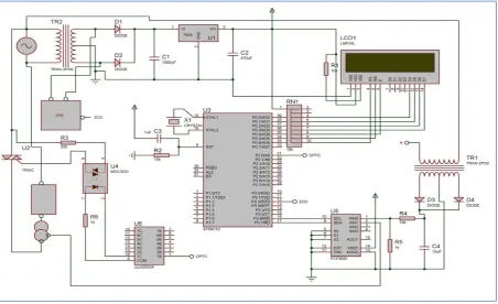
Fig. 1. Block Diagram of Proposed Work
IV.
DESIGN OF EXPERIMENTAL
SET-UP & INSTRUMENTATION
For any inductive load power saver is used to reduce starting current using capacitor bank. Supply is given to the hall current sensor. Current sensor gives signal to A to D converter. To drive A to D converter microcontroller itself clock frequency generator is used. Then signal is supplied to microcontroller which is the heart of the system. Microcontroller gives signal to driver circuit (ULN2003) and this driver circuit is used to operate relay.
The heart of this circuit is microcontroller (89s52) is used to control all components. The basic need of micro-controller is +5v dc supply reset circuit and clock oscillation frequency. Power supply circuit is used to convert 250v AC to 5v and 12 v DC supply. Automatic power factor correction method is used to control power factor at unity with varying firing
angle of a TRIAC. Here CT and PT are connected to A/D converter which converts analog data in digital format and gives to micro-controller as a close loop feedback; further microcontroller gives signal to ULN2003 driver circuit which is used to drive relays, also it gives a gate triggering signal to the TRIAC. As TRIAC works on high voltage i.e. on 220 VAC, and there may be chances of short circuit which results damages to the low power devices like Microcontroller and driver circuit finally all the parameters like voltage across load and current flow through load is display on LCD. As we can’t connect relay unit directly with micro-controller because micromicro-controller works on 5VDC and operating current requires to drive the relay is of 80mA, and driver IC converts a 5 VDC signal to 12V, hence ULN2003 is connected to micro-controller and receive signals from it and operates relay. Here we use PCF8591 8-bit A/D convertor for convert analog data to digital data. Zero-crossing detector circuit is formed by a transistor T1 and T2, which reads/converts every zero crossing of sine wave from positive to negative half
cycle and vice-versa [3].
COMPONENTS OF PROPOSED WORK
i.
AT89S52The whole processing of the device is done by a microcontroller. The micro-controller 89s52 is a
small but powerful micro-controller from
Microchip. The AT89S52 is a low-power, high performance CMOS 8-bit microcontroller with
8Kbytes of in-system programmable Flash
memory. The device is manufactured using Atmel’s high-density non volatile memory technology and is compatible with the industry standard 80C51 instruction set and pin-out. The on-chip Flash allows the program memory to be reprogrammed in-system or by a conventional non- volatile memory programmer. By combining a versatile 8-bit CPU with in-system programmable Flash on a monolithic chip, the Atmel AT89S52 is a powerful micro-controller which provides a highly-flexible and cost effective solution to many embedded control applications. The AT89S52 provides the following standard features: 8K bytes of flash, 256 bytes of RAM, 32 I/O Lines,
Fig. 3. Pin Diagram of AT89S52
Watchdog timer, two data pointers, three 16-bit timer/counters, a six-vector two level interrupt Architecture, a full duplex serial port, on-chip oscillator, and clock circuitry. In addition, the AT89S52 is designed with static logic for operation down to zero frequency and supports two software selectable power saving modes. The Idle Mode stops the CPU while allowing the RAM, timer/counters, serial port, and interrupt system to continue functioning. The Power down mode saves the RAM contents but freezes the oscillator, disabling all other chip functions until the next interrupt or hardware reset.
ii. POWER SUPPLY CIRCUIT
The entire electronics component such transistor, integrated circuits, etc. generally Requires DC for their operation. So AC supply is then stepped down. Now this stepped down AC is converted to DC supply by rectification process .there may be some ripples coming out of Power supply circuit the entire electronics component such transistor,
down. Now this stepped down AC is converted to DC supply by rectification process .there may be some ripples coming out of rectifying unit is bypassed by connecting the capacitor in parallel. Then 12V supply given to the LM7805 regulator. Now as microcontroller, LCD module, relays and other certain ICs requires 5V DC supply for their operation we need a regulated uninterrupted 5V DC supply. This block involves production of 5V DC supply for whole circuit. [3],[4].
Every circuit requires power for its operation. Here we require +5v dc to operate Micro-controller, Relays, and certain ICs. The supply
Fig. 4. Schematic Diagram of LM7805
Voltage of 230v ac is step downed to 12v by using the step-down Transformers. As the circuit requires only the dc supply the in fed ac is converted to dc by using the rectifying unit. The rectifying unit consists of bridge rectifiers comprising diodes for rectification Purpose. Any of the ripples coming out of the rectifying unit is bye passed by connecting the Capacitor in parallel. As the microcontroller circuit requires only +5v dc supply, the outputs is further diminished by the regulator (LM7805) for accurate +5v to the micro-controller
Fig. 5. Schematic of Hall Current Sensor
Circuit. The capacitor is connected in parallel for suppressing the ripples.
iii. HALL CURRENT SENSOR (CT)
iv. ULN2003 (DRIVER)
The ULN2001A, ULN2002A, ULN2003 and ULN2004A are high voltage, high current darlington arrays each containing seven open collector darlington pairs with common emitters.
Each channel rated at 500mA and can withstand
peak currents of 600mA. Suppression diodes are included for inductive load driving and the inputs are pinned opposite the outputs to simplify board layout. These versatile devices are useful for driving a wide range of loads including solenoids, relays DC motors; LED displays filament lamps, thermal print-heads and high power buffers.
V.
RESULTS AND CONCLUSSIONS
i. RESISITVE LOAD
RESISTIVE LOAD
SR.
NO. VOLTAGE
CURRENT POWER TOTAL
CURRENT
TOTAL POWER
MIN MAX MIN MAX
1 220 0.43 0.53 94.6 116.6 0.48 105.6
2 215 0.47 0.55 101.05 118.25 0.51 109.65
3 210 0.47 0.59 98.7 123.9 0.53 111.3
4 205 0.49 0.49 100.45 100.45 0.49 100.45
5 200 0.51 0.65 102 130 0.58 116
6 190 0.67 0.67 127.3 127.3 0.67 127.3
7 180 0.55 0.71 99 127.8 0.63 113.4
9 170 0.73 0.75 124.1 127.5 0.74 125.8
10 160 0.59 0.75 94.4 120 0.67 107.2
11 150 0.59 0.61 88.5 91.5 0.6 90
12 140 0.61 0.78 85.4 109.2 0.695 97.3
13 130 0.8 0.82 104 106.6 0.81 105.3
14 120 0.8 0.8 96 96 0.8 96
15 110 0.61 0.61 67.1 67.1 0.61 67.1
16 100 0.8 0.8 80 80 0.8 80
Table 1. Power Parameters for Resistive Load
Fig7. Power-Voltage Characteristics for Resistive Load
ii.
INDUCTIVE LOAD
INDUCTIVE LOAD
SR.
NO. VOLTAGE
CURRENT
POWER
CURRENT
TOTAL
POWER
TOTAL
0 200
0 50 100 150 200 250
R
ES
IS
TIV
E
PO
WE
R
(w
att
s)
VOLTAGE(Volts)
RESISTIVE LOAD
MIN
MAX MIN MAX
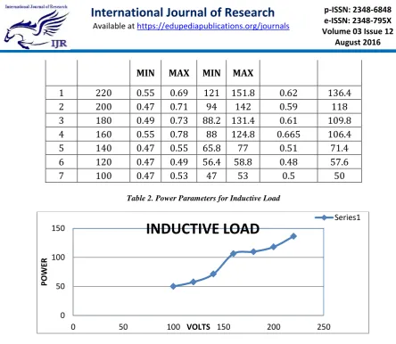
1
220
0.55
0.69
121 151.8
0.62
136.4
2
200
0.47
0.71
94
142
0.59
118
3
180
0.49
0.73
88.2 131.4
0.61
109.8
4
160
0.55
0.78
88
124.8
0.665
106.4
5
140
0.47
0.55
65.8
77
0.51
71.4
6
120
0.47
0.49
56.4 58.8
0.48
57.6
7
100
0.47
0.53
47
53
0.5
50
Table 2. Power Parameters for Inductive Load
Fig8. Power-Voltage Characteristics for Inductive Load 0
50 100 150
0 50 100 150 200 250
PO
WE
R
VOLTS