Article
1
Combined Strengthening Techniques to Improve the
2
Out-of-Plane Performance of Masonry Walls
3
Elena Ferretti 1,* and Giovanni Pascale 1
4
1 Department of Civil, Environmental and Materials Engineering – DICAM, Alma Mater Studiorum
5
Università di Bologna, Viale del Risorgimento 2, 40136 Bologna, Italy; elena.ferretti2@unibo.it;
6
giovanni.pascale@unibo.it
7
* Correspondence: elena.ferretti2@unibo.it; Tel.: +39-051-209-35-15
8
9
Abstract: The purpose of this study is to improve the performance of walls under out-of-plane loads,
10
particularly when subjected to the hammering action of the floors. The idea behind the paper is to
11
provide the masonry walls with a device that behaves like a buttress, without having to build a
12
traditional buttress. The solution presented here consists of a mechanical coupling between the
13
three-dimensional net of steel ribbons of the CAM system and the CFRP strips. Since the steel
14
ribbons of the CAM system have a pre-tension, the mechanical coupling allows the steel ribbons to
15
establish a semi-rigid transverse link between the CFRP strips bonded on two opposite sides of a
16
wall. Therefore, two vertical CFRP strips tied by the steel ribbons behave like the flanges of an
I-17
beam and the flexural strength of the ideal I-beam counteracts the out-of-plane displacements of the
18
wall. The experimental results showed that the combined technique inherits the strong points of
19
both constituent techniques: the delamination load is comparable to that of the specimens reinforced
20
with the CFRP strips and the overall behavior is ductile as for the specimens reinforced with the
21
CAM system. They also allowed us to design a more performing combined technique.
22
Keywords: Masonry buildings; Out-of-plane strength; Hammering actions; Seismic retrofitting;
23
Bracing; Dissipative systems; CAM system; CFRP strips
24
25
1. Introduction
26
When the earthquake direction is orthogonal to a wall of a multi-story building, the wall receives
27
subsequent out-of-plane thrusts from the floors, due to the oscillatory nature of the earthquake forces.
28
In this case, we say that the floors exert a hammering action on the wall.
29
The subsequent pulses of the earthquake may lead the wall to either overturn or break into two
30
parts: this second failure mechanism, the most usual one, activates when an upper kerb retains the
31
wall and takes place with either apartial mechanism (Figure 1a) or a global mechanism (Figure 1b).
32
In both cases, the wall breaks with the formation of a third hinge in correspondence of one of
33
the floors (Figure 2). As far as the meaning of symbols in Figure 2 is concerned:
34
• s is the thickness of the wall;
35
• h is the height of the wall;
36
• W is the self-weight of the wall;
37
• P is the weight transmitted to the wall by the floor;
38
• N is the weight of upper walls and floors;
39
• F is the vertical component of the thrusts given to the wall by arches and vaults;
40
• F is the horizontal component of the thrusts given to the wall by floors, arches and vaults;
41
• a is the distance between P and the hinge in B;
42
• d is the distance between N and the hinge in B;
43
• d is the distance between F and the hinge in B;
44
• h is the distance between F and the hinge in B.
45
46
Figure 1. Out-of-plane collapses in presence of an upper kerb: a) partial collapse; b) global collapse.
47
48
Figure 2. Failure mechanism for the hammering action of a floor when an upper kerb retains the wall:
49
the internal hinge makes the system a labile scheme.
50
Avoiding the mechanisms of out-of-plane collapse that originate from the hammering action of
51
floors is one of the main concerns in modern seismic retrofitting of masonry buildings [1–3]. Actually,
52
engineers have been addressing the problem of counteracting the out-of-plane displacements since
53
the dawn of building technology. One of the first architectural means used for providing support
54
against the lateral forces is the buttress, that is, a structure built against or projecting from a wall
55
(Figure 3): early examples of buttresses are found on the Eanna Temple (ancient Uruk), dating to as
56
early as the 4th millennium BCE.
57
58
Figure 3. Principle of operation of buttresses, to prevent: a) a partial collapse; b) a global collapse.
Historically, buttresses served to strengthen large walls or buildings such as churches.
60
Nowadays, they continue to be useful in large structures such as retaining walls and dams. In these
61
cases, and whenever buttresses counteract, or retain, the lateral force of water or earth, they may be
62
referred to as counterforts.
63
To prevent the buttress projecting too much from the wall, it is possible to make the buttress in
64
the thickness of the wall. In this second case, we must cut the wall for its entire height, build the
65
buttress and restore the masonry wall all around it.
66
Both the external and embedded buttresses are effective, but highly invasive. Moreover, the
67
external buttresses lead to increments of mass that enhance the attraction of seismic forces and the
68
embedded buttresses often involve significant difficulties of realization.
69
In this paper, the authors propose to recuperate the simple idea of the buttress for out-of-plane
70
bracing of walls in masonry buildings, but using new materials and new techniques. Our goal will
71
be twofold: to build a minimally invasive buttress and not to increase the final weight of the
72
retrofitted building too much. Since one of the main concerns in retrofitting masonry buildings is to
73
guarantee a box-type behavior, we have developed the new techniques as improvements of the CAM
74
system, a new three-dimensional continuous retrofitting system that establishes good connections
75
between all the structural elements of the building.
76
2. Some basic notions of the CAM system
77
The CAM system consists of a three-dimensional net of stainless steel ribbons, which form closed
78
loops passing through some holes, obtained by drilling the thickness of the masonry wall (Figure 4a).
79
The use of stainless steel allows us to avoid corrosion problems [4]. When clamping the ribbons, a
80
special tool provides a pre-tension to the ribbons, which then post-compress the masonry that they
81
wrap (Figure 4b). Therefore, the CAM system is an active reinforcement technique that uses tensioned
82
steel ribbons to strengthen the masonry in the same way as the metallic straps strengthen the
83
packages in heavy applications. Because of this analogy, we will call the tensioned ribbons of the
84
CAM system “the straps”.
85
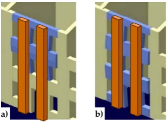
86
Figure 4. a) The three-dimensional net of steel ribbons of the CAM system; b) How a pre-tensioned
87
steel ribbon compresses the masonry.
88
Each drilled hole serves for the passage of up to 6 straps with different directions. Therefore, the
89
transverse holes divide the wall into units of masonry that receive a post-compression by the
pre-90
tensioned straps. In the case of rectangular arrangement of the holes, as in Figure 4a, the units of
91
masonry have the shape of parallelepipeds.
92
In [5], we have shown that the nodes of the rectangular CAM net are subjected to pairs of equal
93
and opposite forces in the plane of the wall (Figure 5a). Consequently, they do not receive any
plane force from the retrofitting system and do not have neither horizontal nor vertical
95
displacements. The only nodal force not balanced by an equal and opposite force is the transverse
96
force (Figure 5b). This means that the actual mechanism of stress-transfer from the rectangular CAM
97
net to the masonry wall is not hydrostatic (Figure 6a), as was believed in the early studies on the
98
CAM system [6–13]. In fact, by eliminating the balanced forces, only the transverse forces will remain,
99
as shown in Figure 6b. Being aware of this last statement is of paramount importance for a structural
100
engineer, as one of the main consequences of replacing Figure 6a with Figure 6b is that the value of
101
stress in the straps becomes upper bounded. In other words, there is an upper limit value of the strap
102
stress, which we cannot overcome without damaging the masonry [5].
103
104
Figure 5. a) Nodal forces in the plane of the wall; b) Nodal forces in the thickness of the wall.
105
106
Figure 6. a) Stress transfer in the hydrostatic state of stress; b) Actual scheme of stress transfer.
107
108
Figure 7. a) Funnel plates of the CAM system; b) Rounded angles of the CAM system.
109
The red elements in Figure 4-Figure 6 are stainless steel protective elements, used in the CAM
110
system to avoid damages at the loop corners when putting in tension the straps. Their design is an
integral part of the CAM patent, filed in 1999 by Dolce and Marnetto. In particular, the patent consists
112
of funnel elements to protect the contours of the holes (Figure 7a) and rounded angles to protect the
113
corners (Figure 7b).
114
In a multi-story building, it is possible to connect walls of different stories easily, by drilling the
115
floors to allow the vertical loops to pass through them. Drilling is also useful at the building corners
116
(Figure 8a) and wall intersections (Figure 8b), to connect orthogonal walls together.
117
118
Figure 8. Connections between orthogonal walls, with details of the arrangement of the ribbons in the
119
thickness: a) at a building corner; b) at an intersection between walls.
120
121
Figure 9. Arrangement of straps to connect perimeter walls to wooden trusses: a) axonometric view
122
from below; b) axonometric view from above; c) plan view.
123
124
Figure 10. Arrangement of straps to connect perimeter walls to wooden beams: a) axonometric view
125
from above; b) plan view.
126
127
Figure 11. Box-type behavior supplied to the building by the CAM system [10].
Moreover, it is possible to connect the perimeter walls to wooden trusses (Figure 9), wooden
129
beams (Figure 10) and metallic beams (Figure 4a), thus improving the wall to roof and wall to floor
130
connections. Improving the structural connections gives continuity to the retrofitting system, making
131
it possible to connect all the structural elements together. Therefore, the CAM system is able to
132
provide the building with an overall box-type behavior (Figure 11).
133
The holes drilled in the masonry wall behave as cylindrical hinges (Figure 12a), even when we
134
fill the holes with mortar after retrofitting. This is particularly detrimental to the rectangular
135
arrangement of the CAM system. Actually, the straps form unbraced rectangular frame structures
136
with hinged nodes (Figure 12b), both in the plane of the wall and the thickness of the wall. Since the
137
unbraced rectangular frame structures are not able to withstand lateral forces and sway laterally, the
138
rectangular arrangement of the CAM system is labile along both the in-plane (Figure 13a) and
139
transverse directions of the wall (Figure 13b). In particular, it is not able to counteract the out-of-plane
140
loads, that is, is not suitable for increasing the ultimate load of collapse when the directional
141
properties of the earthquake involve a hammering action of floors on the walls. This is why we need
142
to combine the CAM system with other reinforcement techniques for increasing the wall resistance
143
to hammering actions.
144
145
Figure 12. Hinged mechanisms: a) in the wall thickness; b) in the wall plane.
146
147
Figure 13. Loading of a wall reinforced with the CAM system: a) shear loading in the midplane [13];
148
b) out-of-plane loading [13].
149
3. Techniques of cross bracing in the thickness of the wall
150
3.1.Re-arrangement of the CAM straps
151
In [14], we have shown that it is possible to re-arrange the CAM straps to find a statically
152
determined strap configuration for lateral loads, in order to increase the load-bearing capacity for
153
shear loads. In fact, by arranging the straps along the two principal directions of stress for shear stress
154
(forming angles of ±45° with respect to the horizontal direction [15]), we obtain a cross bracing effect
155
in the plane of the wall (Figure 14).
156
The idea of turning the straps in search of a cross bracing effect suggests us a possible application
157
to counteract out-of-plane displacements: to gain an effect of cross bracing in the thickness, we should
158
drill the wall along directions not orthogonal to the wall, with positive and negative slopes alternately
159
(Figure 15a). Though theoretically possible, this solution is impracticable because too complicated
160
from the technological point of view. Therefore, to increase the load-bearing capacity for out-of-plane
161
loads we must develop some alternative solutions.
163
Figure 14. Optimized arrangement of straps for in-plane shear loads.
164
165
Figure 15. a) Inclined perforations to achieve a cross-bracing effect in the thickness; b) Behavior
166
scheme of a braced rectangular frame structures with hinged nodes.
167
3.2.Application of the CAM system together with CFRP strips
168
The second technique exploits the capacity of the CAM system of establishing a transversal link
169
with designable stiffness. In fact, once we have chosen the type of stainless steel and the cross-section
170
of the straps, we can increase the stiffness of the transversal link by increasing the number of straps
171
per loop (up to a maximum of 4 straps per loop).
172
It is precisely the possibility of designing the stiffness of the transversal link that allows us to
173
use the CAM system to build an embedded buttress. If fact, if we wanted to build an embedded
174
buttress with a traditional technique, we would probably incorporate an FRP I-beam in the thickness
175
of the wall, placing the two flanges vertically on the two faces of the wall to maximize the moment of
176
inertia. As well known, the cross-section of a bent I-beam (Figure 16a) behaves as two ideal
point-177
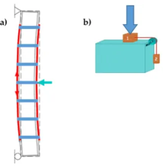
masses, linked by a stiffness constraint (Figure 16b). The idea underlying this paper is that it is
178
possible to reverse the path in Figure 16, moving from two masses, linked by a stiffness constraint, to
179
an (ideal) beam under bending load. In this case, if we were able to establish a stiffness constraint
180
between two masses placed on the two sides of the masonry wall, we could obtain an (ideal)
181
embedded buttress without having to cut the masonry wall to insert a beam.
182
183
Figure 16. Ideal scheme of behavior of an I-beam: two point masses, linked by a stiffness constraint.
Following this inspiring idea, we decided to exploit the stiffness constraint provided by the CAM
185
straps to link together the CFRP strips bonded on the two opposite sides of a masonry wall, so that
186
the two CFRP strips behave like the two flanges of an ideal CFRP I-beam (Figure 17). To this aim, we
187
used some straps of a continuous CAM net to tie together the CFRP strips bonded on the two opposite
188
sides of the masonry wall, one in front of the other as in Figure 17. Since the CAM net crosses the
189
floors easily, establishing effective wall-to-wall connections (Section 2), the ideal I-beam can extend
190
to the entire height of the building, thus counteracting the hammering actions of the floors.
191
In the explanatory scheme shown in Figure 17, the masonry wall enclosed between the two CFRP
192
strip acts as a lost formwork, as it serves to define the distance between the two flanges of the ideal
193
I-beam and remains within the construction. The thicker the masonry wall, the higher the web and,
194
consequently, the greater the moment of inertia of the ideal I-beam [16].
195
196
Figure 17. How the ribbons of the CAM system and the CFRP strips work together to provide us with
197
a bracing effect in the thickness, similar to that given by an embedded I-beam acting as a buttress.
198
199
Figure 18. Buckling of the compressed CFRP strip, when: a) the load is on the side opposite to that of
200
buckling; b) the load is on the side of buckling and pushes on the compressed CFRP strip.
Before tying the two strips of CFRP together, the strips work independently, in the sense that
202
there is no bound between them. In particular, the ultimate flexural strength of the masonry wall
203
depends on the strip applied on the stretched side. In fact, due to buckling, the strip on the
204
compressed side of a bent wall undergoes delamination before the stretched strip (Figure 18).
205
The delamination of the stretched strip occurs when the shear forces at the strip-beam interface
206
exceed a limit value. In absence of straps, as in Figure 18, the limit value depends on the properties
207
of the resin, which establishes a chemical bond between the strip and the beam.
208
Figure 19 explains the behavior of the other possible type of bond between two bodies, the
209
physical bond, when a normal force presses the two bodies together. In particular, in Figure 19:
210
• P is the weight force, exerted by body 1 on the support plane;
211
• N is the normal reaction force, equal and opposite to P, exerted by the support plane on body 1;
212
• T is the shear force, exerted by the hanging body (body 2) on the support plane;
213
• A is the friction force, developed by the support plane as a reaction to T: in static conditions, A
214
is equal and opposite to T;
215
• F is the resultant force acting on the support plane (the components of F are P and T);
216
• Φ is the resultant force acting on body 1 (the components of Φ are N and A);
217
• 𝛼 tan 𝐴 𝑁⁄ is the angle formed by Φ with the direction orthogonal to the support plane;
218
• 𝜙 is the angle of static friction, that is, the maximum inclination angle of the support plane
219
before which body 1 will begin sliding on it;
220
• tan 𝜙 is the coefficient of static friction, a dimensionless scalar value that describes the
221
maximum ratio of the force of friction between two bodies at rest relative to each other and the
222
force pressing them together;
223
• tan 𝜙 is the coefficient of kinetic friction, that is, the ratio of the force of friction between two
224
bodies in relative motion and the force pressing them together.
225
226
Figure 19. a) Forces at the interface between a body at rest (body 1) and its support plane; b) Cone of
227
static friction; c) Cone of kinetic friction.
228
Both coefficients of friction depend on the pair of surfaces in contact. For a given pair of surfaces,
229
the coefficient of static friction is usually higher than the coefficient of kinetic friction.
230
The angle 𝜙 is equal to half the aperture of the static friction cone (the right circular double
231
cone in Figure 19b). For bodies at rest relative to each other, the angle 𝛼 cannot never exceed 𝜙 .
232
If Φ falls within the cone of static friction, there is no relative displacement between body 1 and
233
the support plane. When 𝛼 equals 𝜙 , Φ reaches the lateral surface of the cone of static friction. This
234
limit condition separates the state at rest from the state of motion: as soon as Φ touches the lateral
235
surface, the friction force A decreases so that Φ lies down along a generatrix of the lateral surface of
236
the kinetic friction cone (the right circular cone in Figure 19c). Therefore, A and T are no longer
237
vectors of equal magnitude and body 1 starts to slide along the direction of T.
Well, when the straps tie the CFRP strips together, the straps add a physical bond to the chemical
239
bond provided by the resin, because the pre-tension of the straps presses the CFRP strips against the
240
masonry wall (Figure 20a) in the same way as the compression force of Figure 20b presses body 1
241
against the support plane.
242
243
Figure 20. a) The straps delay delamination on both sides of the beam; b) Scheme of the physical bond
244
added by the straps: the compression force represents the action of the straps on the CFRP strips.
245
246
Figure 21. a) Limit surface of the chemical bond: the shear forces determine the limit condition,
247
independently of the compression forces; b) Cone of static friction; c) Cone of cohesive static friction.
248
As far as the transition from the state at rest to the state of motion is concerned, when we combine
249
the cylinder of Figure 21a, which represents the limit surface of the chemical bond provided by the
250
resin, with the cone of static friction (Figure 21b), we obtain the right circular double truncated cone
251
of Figure 21c. Therefore, Figure 21c represents the limit surface of the cohesive physical bond,
252
provided by the resin and the straps acting simultaneously (cone of cohesive static friction).
253
Compared to the chemical bond, the advantage of the cohesive physical bond is twofold:
254
• On the compressed side, the straps prevent the buckling of the CFRP strip, the main cause of
255
delamination on that side.
256
• On the stretched side, the compression forces exerted by the straps on the CFRP strip modify the
257
shape of the limit surface, from the cylinder of Figure 21a to the double truncated cone of Figure
258
21c. As a result, the CFRP strip can withstand higher shear forces before the head of Φ touches
259
the limit surface. Since the shear forces depend on the bending load linearly, this ultimately
260
means that the stretched CFRP strip will undergo delamination for higher values of the bending
261
load. Therefore, the strapping delays the delamination on the stretched side.
The masonry wall benefits from the bracing effect provided by the ideal I-beam until the
263
stretched strip undergoes delamination. After that, the actual behavior of the retrofitted system
264
depends on the stiffness of the transversal link provided by the straps (see Section 4.5).
265
4. Experimental program
266
4.1.Funnel plates and rounded angles
267
The experimental program on the effectiveness of the combined technique discussed in Section
268
3.2 includes the design of new protective elements for the loop corners. The adopted solution, shown
269
in Figure 22, consists of 3D printed elements, made with PLA filament, which substitute the CAM
270
protective elements of Figure 23.
271
272
Figure 22. 3D printed funnel plates and rounded angles.
273
274
Figure 23. Protective elements of the CAM system [6].
275
PLA (Polylactic Acid) is one of the two most commonly used filaments in FDM (fused deposition
276
modeling) 3D printing, with the other being ABS filament. Our choice fell on the PLA filament for
277
environmental reasons. In fact, PLA filament is one of the most eco-friendly 3D printer materials
278
available, because the polymerized lactic acid comes from annually renewable resources (cornstarch,
279
tapioca roots, sugarcane or other sugar-containing crops). Furthermore, it requires less energy to
280
process compared to traditional (petroleum-based) plastics.
281
PLA is a thermoplastic, biodegradable and non-toxic polyester. During printing, the PLA
282
filament emits a pleasant sugary scent and releases only carbon dioxide into the air. Moreover, one
283
can simply discard unwanted PLA printed objects in the soil or aggressive natural environments,
284
where they will naturally decompose. For example, an item made of PLA plastic in the ocean has a
285
degradation time of the order of six months to two years, while conventional plastics take from 500
286
to 1,000 years to degrade.
287
It is important to point out that, although PLA will degrade in an exposed natural environment,
288
it is very robust in any normal application or when adequately protected against degradation: its
289
stiffness and hardness make it similar to iron.
290
Both the 3D printed plates and angles have rounded external corners – where they adhere to the
291
straps – and internal corners at 90°, to improve the coupling with the wall (Figure 22). The rounded
292
external corner prevents the strap from bending too tightly and tearing during pre-tensioning. It is
293
worth noting that only 3D printing can provide us with protective elements with these geometric
294
characteristics, as it is impossible to obtain different shapes for external and internal corners with the
295
traditional hot forming technique used for the CAM elements in Figure 23.
Finally, the flat parts of the 3D printed protective elements have a truss shape. When positioning
297
the protective elements, the mortar fills the truss structure: this improves the adherence between the
298
masonry wall and the protective elements, once the mortar has hardened (Figure 24).
299
300
Figure 24. 3D printed elements after placing in place: a) rounded angles; b) funnel plates.
301
4.2.Straps and seals
302
Figure 25 shows the stainless steel straps and seals of the CAM system. The comparison between
303
the stress/strain curves of the displacement controlled tensile tests, performed on CAM straps with
304
and without seals (Figure 26), shows that the CAM junction is weaker than the straps. In fact, the seal
305
of the CAM system breaks at a load that is lower than the breaking load of the strap. Consequently,
306
the strength of a strap clamped by the CAM system is lower than the strength of the strap alone.
307
Figure 26 also shows that the seal modifies the stiffness of the jointed steel ribbons. In fact, the
308
initial slope of the stress/strain curves for the jointed specimens is lower than for the specimens
309
without junctions, which means that applying a seal decreases the stiffness of the tying system.
310
Finally, the failure mechanism of the jointed specimens of Figure 26 is brittle, as the specimens
311
break shortly after the point of maximum stress. This causes the CAM junctions to break almost
312
suddenly.
313
314
Figure 25. a) Steel ribbons and seals of the patented CAM system [10]; b) A detail of a CAM seal.
315
316
Figure 26. Stress/strain diagrams of the CAM ribbons, with and without seals [6].
317
Since the brittle junctions do not allow the straps to show signs of warning against the crisis, one
318
of the aims of our experimental program was to equip the tying system with ductile junctions. Figure
319
27 shows the stainless steel seal of the experimental program, used to clamp 19 mm wide and 1 mm
thick stainless steel straps. Since these straps are not of the type patented with the CAM system, we
321
will call them “the CAM-like straps”.
322
To investigate the behavior of the new junction, we performed tensile tests under displacement
323
control on the following 4 specimens (Figure 28), where the steel ribbons were cut by the stainless
324
steel straps of the experimental program:
325
• Specimen L2, consisting of a steel ribbon without junction;
326
• Specimen L3, consisting of a steel ribbon without junction;
327
• Specimen S2, consisting of 2 pieces of steel ribbon, fastened together by 1 seal;
328
• Specimen S3, consisting of 2 pieces of steel ribbon, fastened together by 2 seals;
329
330
Figure 27. The seal used in the experimental program.
331
332
Figure 28. The four specimen for the characterization of the CAM-like ribbons and new junctions.
333
The stress/strain diagrams in Figure 29 clearly show that the strength of the CAM-like straps is
334
much lower than the strength of the straps used with the patented CAM system (Figure 26).
335
As far as the initial stiffness is concerned, the application of the seal decreases the stiffness of the
336
tying system even for the new junction. In fact, in Figure 29 the initial slope of the stress/strain
337
diagrams of Specimens S2 and S3 is lower than the initial slope of the stress/strain diagrams of
338
Specimens L2 and L3.
339
340
Figure 29. Stress/strain diagrams of the CAM-like ribbons, with and without seals.
Moreover, the yield strength of Specimens S2 and S3 is almost the same as the yield strength of
342
Specimens L2 and L3. The maximum stress of Specimens S2 and S3, on the contrary, is lower than
343
the maximum stress of Specimens L2 and L3. Thus, also clamping by means of the seal in Figure 27
344
decreases the strength of the straps. Nevertheless, now the behavior of the junction is ductile, as a
345
stage of oscillatory stress separates the maximum stress from the ultimate stress (Figure 29).
346
Therefore, the junction no longer breaks fragilely.
347
The ductile behavior of the jointed steel ribbons is a consequence of the sliding that takes place
348
– into the seal – between the ends of the straps. The sliding into the seal is also the main cause of the
349
crisis: while in the CAM system the junction fails due to the breaking of the seal, this second time the
350
junction fails when one of the two ends slips off from the seal (Figure 30). This failure mechanism
351
also explains why the oscillatory stage of Specimen S3 (with 2 seals) is longer than the oscillatory
352
stage of Specimen S2 (with just 1 seal): since 2 seals are more effective than just 1 seal in counteracting
353
the sliding, unfastening the junction of the specimen with 2 seals needs more time. In other words,
354
the junction of Specimen S3 withstands a higher relative displacement than Specimen S2.
355
356
Figure 30. How the new junction unfastens, with: a) 1 seal; b) 2 seals.
357
It is worth noting that even leaving longer ends when cutting the straps allows us to delay
358
unfastening, as happens when using two seals. In the specific case of our experimental program,
359
however, we decided not to use either longer ends or two seals, because an ultimate strain of more
360
than 5% (achieved with Specimen S2) is already satisfactory for our purposes.
361
4.3.Mechanical characterization of bricks and mortar
362
The mechanical characterization of bricks took place by performing uniaxial compression tests
363
on 6 brick specimens (Figure 31a), cut from 3 different bricks of the experimental program. The
364
methods used to cut and dry the specimens and carry out the uniaxial compression tests comply with
365
UNI EN 772-1. Table 1 collects the results of the compression tests.
366
The mortar of the experimental program is a single-component, fiber-reinforced,
sulfate-367
resistant, shrinkage controlled mortar, useful for repairing and reinforcing concrete structures, mixed
368
masonry, historic walls and curtain walls.
369
The mechanical characterization of the mortar complied the specifications provided by UNI EN
370
1015-11/2007, which establishes to perform both three-point bending flexural tests on prismatic
371
specimens and uniaxial compression tests on cubic specimens. Figure 32 shows the 6 prismatic
372
specimens of the experimental program. After the flexural tests, each prismatic specimen provided
373
us with two cubes for the uniaxial compression test.
374
Table 2 shows the results of the three-point bending flexural tests on the 6 prismatic specimens
375
and the uniaxial compression tests on the 12 cubic specimens (EN 196-1:2016). Since the average
376
378
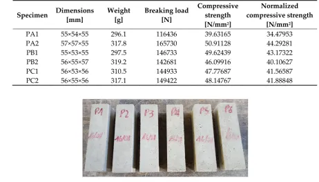
Figure 31. The 6 specimens tested for brick characterization: a) before the test; b) after the test.
379
Table 1. Geometric and mechanical characteristics of the 6 brick specimens.
380
Specimen Dimensions [mm]
Weight [g]
Breaking load [N]
Compressive strength [N/mm2]
Normalized compressive strength
[N/mm2]
PA1 55×54×55 296.1 116436 39.63165 34.47953
PA2 57×57×55 317.8 165730 50.91128 44.29281
PB1 55×53×55 297.5 146733 49.62439 43.17322
PB2 56×55×57 319.2 142681 46.09916 40.10627
PC1 56×53×56 310.5 144933 47.77687 41.56587
PC2 56×55×56 317.1 149422 48.14767 41.88848
381
382
Figure 32. The 6 specimens for three-point bending flexural tests on mortar.
383
Table 2. Geometric and mechanical characteristics of the mortar specimens.
384
Specimens of the flexural
tests
Dimensions [mm]
Weight [g]
Breaking load in bending
[N]
Flexural Strength [N/mm2]
Specimens of the compression
tests
Breaking load in compression
[N]
Compressive Strength [N/mm2]
P1 40×40×160 466.42 1758 4.12 P1A 30530 19.08
P1B 36730 22.96
P2 40×40×160 469.81 1838 4.31 P2A 30980 19.36
P2B 30930 19.33
P3 40×40×160 470.42 1443 3.38 P3A 27500 17.19
P3B 28530 17.83
P4 40×40×160 459.63 1885 4.42 P4A 34544 21.59
P4B 27730 17.33
P5 40×40×160 463.81 1990 4.66 P5A 33880 21.18
P5B 35200 22.00
P6 40×40×160 462.01 1598 3.75 P6A 30400 19.00
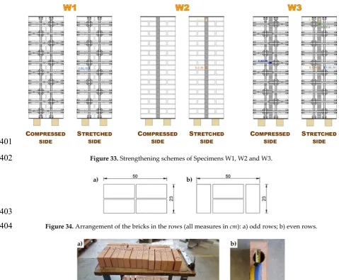
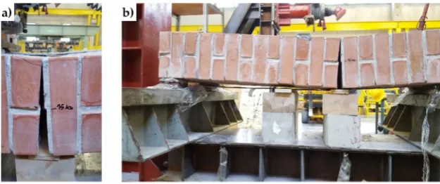
4.4.Specimens W1, W2 and W3
385
Figure 33 shows the first set of 3 specimens of the experimental program, where:
386
• The three brick walls are of identical dimensions (50 × 146 × 23 cm).
387
• The bricks are of the Bolognese type: they measure 24.5 cm in length, 5.5 cm in height and 11 cm
388
in depth. Figure 34 shows how we arranged the bricks in the odd and even rows. In particular,
389
in the odd rows we adjusted the length of the end bricks to fit the thickness of the wall. For the
390
mechanical characteristics of the bricks, see Section 4.3.
391
• Specimen W1 is a drilled masonry wall, with the holes arranged in quincunxes. This choice
392
minimizes the number of holes and gives rise to two three-dimensional nets of straps, staggered
393
along the horizontal and vertical directions.
394
• Specimen W2 is an undrilled wall, where we applied some CFRP strips along the two vertical
395
centerlines of the main faces, specifically, two strips side by side for each centerline. The CFRP
396
strips are 25 mm wide and 1.2 mm thick.
397
• Specimen W3 is a drilled wall, with the holes arranged in quincunxes, where we applied both
398
the staggered nets of straps and the side-by-side CFRP strips along the vertical centerlines. In
399
particular, we used some straps of both three-dimensional nets to tie the strips together.
400
401
Figure 33. Strengthening schemes of Specimens W1, W2 and W3.
402
403
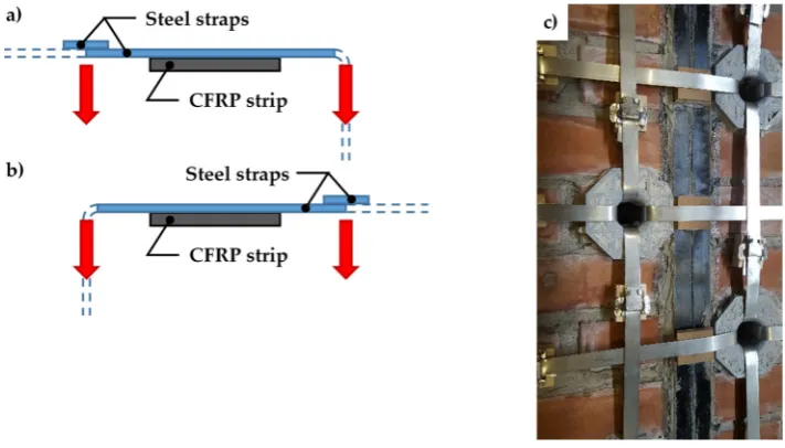
Figure 34. Arrangement of the bricks in the rows (all measures in cm): a) odd rows; b) even rows.
404
405
Figure 35. a) Preparation of the bricks to be drilled; b) Detail of a brick after drilling.
• Drilling of the bricks for Specimens W1 and W3 took place on the individual bricks (Figure 35a),
407
before starting to build the walls. This allowed us not to face damages or stability problems of
408
the walls during drilling. The core drill used to remove the brick cores has a diameter of 4 cm
409
(Figure 35b).
410
• The protective elements at the loop corners of Specimens W1 and W3 are those of the research
411
activity discussed in Section 4.1.
412
• The straps used for the active confinement of Specimens W1 and W3 are the CAM-like straps
413
described in Section 4.2.
414
• The stainless steel seals used for Specimens W1 and W3 are those described in Section 4.2.
415
• For both Specimens W1 and W3, we used just one strap per loop.
416
• The strapping of Specimens W1 and W3 took place in two steps, first arranging all the straps
417
spanning along the short direction (transverse straps) and, secondly, completing the strapping
418
with the straps spanning along the long direction (longitudinal straps). This allows the
419
longitudinal straps to pass over the transverse straps at the intersections between the straps
420
(Figure 36c). As a result, the pre-tension of the longitudinal straps pushes the transverse straps
421
against the wall, allowing the transverse straps to block the CFRP strips more firmly. Therefore,
422
the transverse straps load the CFPR strips symmetrically, according to schemes a) and b) of
423
Figure 36, alternatively.
424
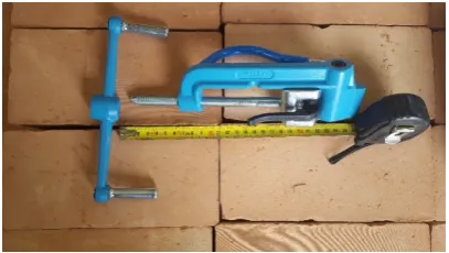
• The tool used to pre-tension the straps of Specimens W1 and W3 is the manual strapping tool
425
for steel shown in Figure 37.
426
• We instrumented the three specimens with strain gauges on both sides (Figure 33).
427
• After curing and instrumentation, we overturned the 3 specimens in horizontal configuration
428
(Figure 38b).
429
• We placed some flat steel bars on the central cross-sections of the three specimens, in order to
430
distribute the load given by the testing machine. The arrangement of the flat steel bars allowed
431
the load not to compress the straps and, in Specimens W2 and W3, the upper CFRP strips (Figure
432
39).
433
• We performed three-point bending flexural tests under in displacement control on the three
434
specimens, by using some Linear Variable Differential Transformers (LVDTs) to acquire the
435
displacements at the ends and the middle point on the lower faces.
436
437
Figure 36. a) Cross-section view: the longitudinal strap pushes down on the transverse strap to the
438
left of the CFRP strip (not to scale); b) Cross-section view: the longitudinal strap pushes down on the
439
transverse strap to the right of the CFRP strip (not to scale); c) Detail of the intersections between the
440
straps: the arrangement of the transverse straps follows the scheme sequence a, b, a.
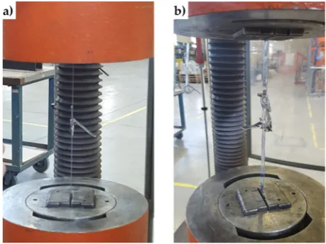
442
Figure 37. Manual strapping tool for steel.
443
444
Figure 38. Specimen handling: a) harness; b) overturning; c) positioning on the testing machine.
445
446
Figure 39. Arrangement of the flat steel bars on the central cross-section.
447
In [16], we have already provided some early results on the effectiveness of the combined
448
technique discussed in Section 3.2. Here, we will focus on the post-delamination behavior of a
449
masonry wall after retrofitting by the combined technique. In particular, we will show further
450
experimental results on the strapped masonry walls, to answer the question on whether the stiffness
451
of the transversal link modifies the post-delamination behavior or not.
452
The increase in ductility is the most important result with regard to the out-of-plane behavior of
453
strapped masonry walls. Actually, since the strength of the steel ribbons is much greater than the
454
masonry strength, the straps continue to wrap masonry even after masonry crushing. This is of
455
fundamental importance in real buildings, as people do not risk that some part of the structure will
456
hit them, due to the building collapse. Therefore, the strapping acts as a reinforcement system before
457
the structural damage occurs and a protection device after the structural damage had occurred.
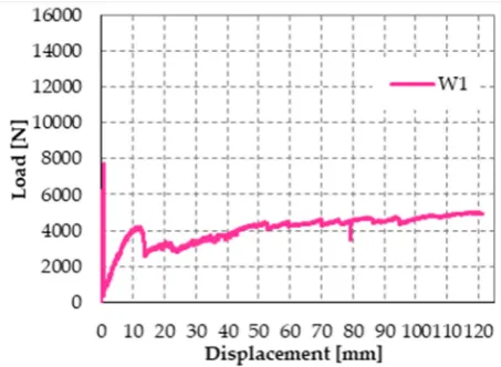
The mechanism of safeguarding life allowed by strapping is particularly evident in Figure 40,
459
which is a snapshot of Specimen W1, taken at the end of the test: although the internal hinge of Figure
460
2 has formed and provided a large relative rotation, the longitudinal straps still keep the beam in
461
equilibrium. Actually, Specimen W1 never collapsed during the flexural test: to avoid
462
instrumentation damages, the operator had to stop the test for a vertical displacement of the loading
463
piston of 12.124 cm (Figure 41), while the specimen would have withstood further increases in vertical
464
displacement. When the operator stopped the flexural test, the specimen was still resisting a load of
465
5 kN, which is about 65% of the hinge formation load (7.7 kN), and the load was still increasing.
466
467
Figure 40. The internal hinge of Specimen W1, which has formed close to the loading piston.
468
469
Figure 41. Load/displacement diagram of Specimen W1.
470
Due to the low pre-tension stress supplied to the straps, the load of hinge formation is the same
471
for the strapped and non-strapped masonry walls. Therefore, the first-peak load of 7.7 kN is the
472
failure load for plain specimens.
473
Furthermore, the final vertical displacement is about 189% of the vertical displacement at the
474
first peak (0.064 cm), that is, the vertical displacement at failure for plain specimens. This makes the
475
opening of the internal hinge ductile. Finally, the vertical displacement immediately after the first
476
peak in Figure 41 is almost the same as the vertical displacement at the first peak. In other words, the
477
rotation around the internal hinge at the formation of the hinge itself was almost nil. After that, the
478
crack under the internal hinge opened very slowly (Mode I: opening mode), in a controlled manner.
479
It is worth noting that no straps broke during crack opening. Therefore, the tying system is fully
480
adequate to safeguard life even if the strength of the CAM-like straps is much lower than the strength
481
of the patented CAM ribbons (see Figure 26 and Figure 29).
482
Figure 42 shows the load/displacement diagram for Specimen W2, with a maximum load that is
483
twice the maximum load of Specimen W1. When compared with the load/displacement diagram in
484
Figure 41, Figure 42 shows that the CFRP reinforcement makes the masonry wall stronger, but also
485
much more brittle than the steel straps.
487
Figure 42. Load/displacement diagram of Specimen W2.
488
489
Figure 43. a) Length of the crack for a load of 15 kN (delamination load of the compressed CFRP strip);
490
b) Detail of the delamination on the compressed side, just above the crack.
491
492
Figure 44. a) Opening of the crack (Mode I), at the delamination load of the stretched CFRP strip; b)
493
Delamination on the stretched side.
494
The peak in Figure 42 corresponds to the delamination of the compressed strip, which detached
495
itself starting from the localization cross-section of the internal hinge. Figure 43 is a snapshot of the
496
cross-section where the internal hinge localized, taken at the maximum load (peak load of Figure 42).
497
In particular, the mark in Figure 43a shows the crack length for a load of 15 kN, while Figure 43b is a
498
detail of the CFRP strip delamination, initiated on the compressed side, just above the crack of Figure
499
43a. As shown by the mark in Figure 43a, initially the crack involved only half the thickness of the
500
specimen. Then, the cross-section underwent a short phase of localized deformations, leading to the
501
increase in vertical displacement – at almost constant load – which characterizes the diagram after
502
the peak of Figure 42: this is the phase in which the cross-section behaved as a plastic hinge. The
503
plastic phase ended with the delamination of the lower CFRP strip, which detached itself starting
504
from the end that was farthest away from the internal hinge (Figure 44b).
The effect provided by the two reinforcement systems that act simultaneously on the masonry
506
wall is twofold, as the combined technique increases both the strength and the ductility. In fact, the
507
maximum load in Figure 45 is comparable to that given by the CFRP strips alone (about twice the
508
failure load of the masonry wall) and the post-peak behavior is as ductile as that offered by the steel
509
straps alone.
510
It is worth noting that, while the increased ductility of the masonry wall leads to high
511
displacements, it does not involve a high displacement rate, which could be dangerous for people
512
standing in a real building. In fact, at the maximum load of Specimen W3 the load decreases abruptly
513
while the vertical displacement is almost constant (Figure 45). This means that, though the internal
514
hinge forms at the peak, the relative rotation between the two hinged cross-sections is negligible at
515
the peak. Moreover, after the peak the relative rotation increased in a controlled manner, as the steel
516
straps provide the hinge with a plastic behavior. Therefore, the straps allow the internal hinge to
517
achieve high relative rotations without ever losing equilibrium. In other words, Specimen W3 moved
518
along a path of stable equilibrium throughout the duration of the flexural test.
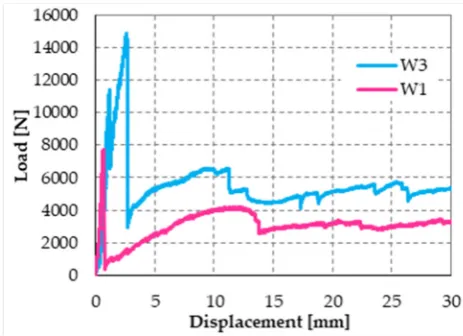
519
520
Figure 45. Load/displacement diagrams of Specimens W1 and W3: displacement field truncated at
521
the value of 30 mm.
522
The post-delamination behavior of Specimen W3 (diagram in Figure 45 after the maximum load)
523
shows that the steel straps retain the delaminated strip, allowing the wall to withstand loads higher
524
than the post-peak loads of Specimen W1 (retrofitted only with steel straps). This means that the wall
525
can benefit of the strengthening effects of both CFRP strips even after the delamination of the
526
stretched strip, although only in part. In other words, the I-beam behavior of the combined technique
527
does not end with the strip delamination: it survives the delamination with a decreased stiffness,
528
which depends on the stiffness of the transversal link. Therefore, increasing the number of straps per
529
loop should increase the load-bearing capacity after delamination, as it increases the stiffness of the
530
transversal link.
531
To verify this latest statement, we restored Specimen W3 (after testing) and increased the
532
number of straps per loop. We then tested the restored specimen by performing a further three-point
533
bending flexural test in displacement control. This also allowed us to evaluate the effectiveness of the
534
combined technique to restore a damaged structural element.
535
The new label of Specimen W3 after restoration and strapping is “Specimen W4”.
536
4.5.Specimen W4
537
The preparation of Specimen W4 took place as follows:
538
• Removal of all damaged straps of Specimen W3;
539
• Cleaning of the specimen surface, in correspondence of the delaminated CFRP strips;
540
• Removal of the mortar on the cross-section where Specimen W3 opened into two parts;
• Restoration of the specimen integrity, by walling together the two parts of Specimen W3;
542
• Curing of the mortar on the restored cross-section;
543
• Bonding of new CFRP strips on both sides of the specimen;
544
• Strapping of the specimen according to the scheme of Figure 46, by positioning the vertical straps
545
over the horizontal straps (as for Specimens W1 and W3).
546
After restoration and strapping, we inverted Specimen W4 to load the face that was on the
547
stretched side of Specimen W3.
548
549
Figure 46. Scheme of strapping for Specimen W4.
550
551
Figure 47. a) Specimen W3 at the end of the flexural test; b) Detail of the failure cross-section, where
552
the crack propagation occurred in both Mode I (opening mode) and Mode II (sliding mode).
553
554
Figure 48. a) Specimen W4 at the end of the flexural test; b) Detail of the 2 failure cross-sections: on
555
the left cross-section the crack propagation occurred in Mode I, while on the right cross-section the
556
crack propagation occurred in both Mode I and Mode II.
Figure 47 and Figure 48 allow us to compare the failure cross-sections of Specimen W3 and
558
Specimen W4: the internal hinge of Specimen W4 localized on the same cross-section as the internal
559
hinge on Specimen W3 (9th mortar bed joint from the left). In addition to this, a second internal hinge
560
has formed for Specimen W4, on the 8th mortar bed joint from the left (Figure 48b). This happened
561
because the strapping provides an infinite degree of internal hyperstaticity to the isostatic
static-562
scheme of the hinged supported I-beam, allowing the formation of multiple plastic hinges on the
563
cross-sections, without ever reaching a labile configuration (until the straps are broken).
564
The load/displacement diagram of Specimen W4 confirmed the general features of Specimen W1
565
and Specimen W3: the use of the steel straps made the retrofitted system extremely ductile, to such
566
an extent that the specimen did not experienced collapse up to vertical displacements of the order of
567
10 cm (Figure 49). Even in the latter case, indeed, the operator had to stop the flexural tests to avoid
568
instrumentation damages, while the specimen would have withstood further increases in
569
displacement. Note that the load/displacement diagram of Specimen W3 in Figure 49 is much shorter
570
than the diagrams of both Specimen W1 and Specimen W4 only because the instrumentation setup
571
prompted the operator to interrupt the flexural test well in advance.
572
573
Figure 49. Comparison between the load/displacements diagrams of the 4 specimens.
574
Figure 49 suggests us some further considerations:
575
• The restoration was successful, as the delamination load of Specimen W4 is comparable to the
576
delamination load of Specimen W2 (retrofitted only with CFRP strips).
577
• Specimen W4 underwent delamination at 16.387 kN, while Specimen W3 underwent
578
delamination at 14.904 kN. Therefore, the delamination load after restoration (Specimen W4) is
579
10% higher than the delamination load before restoration (Specimen W3). As the number of steel
580
straps of Specimen W4 is higher than the number of steel straps of Specimen W3, this confirms
581
that a higher compression load on the CFRP strips delays delamination and increases the
582
delamination load, as discussed in Section 3.2. In fact, a higher compression load increases the
583
magnitude of the normal reaction force, N, in Figure 21c, thus increasing the distance between
584
the resultant force acting on a CFRP strip, Φ, and the lateral surface of the cone of cohesive static
585
friction.
586
• Upon delamination of the stretched CFRP strip, the load withstood by Specimen W4 decreased
587
abruptly, but to a lesser extent than for Specimen W3. In fact, the residual load withstood by
588
Specimen W4 after delamination (7.083 kN) is about 236% of the residual load withstood by
589
Specimen W3 (3.004 kN). Once again, the observed behavior depends on having increased the
590
number of steel straps: the friction forces at the interface between CFRP strips and masonry wall
591
– activated by the compression loads provided by the steel straps – counteract the sliding of the
592
delaminated strip. Consequently, the straps continue to tie the two flanges of the ideal I-beam
593
together even after delamination. Moreover, the stiffness of the constraint established between
594
the two flanges depends on the friction forces. Therefore, the greater the number of steel straps,
the greater the friction forces and, consequently, the constraint stiffness. In conclusion, the
596
greater the number of steel straps, the greater the residual load after delamination.
597
• The positive contribution of increasing the number of steel straps becomes even more evident in
598
the post-delamination stage: after the initial decrease, the post-delamination load of Specimen
599
W4 increases and maintains values that are much higher than those of Specimen W3. Even in
600
the latter case, the increase in load depends on the I-beam behavior of the two CFRP strips,
601
allowed after delamination by the friction forces developed at the interface with the masonry
602
wall.
603
• In Specimen W4, the post-delamination load increased up to exceed the delamination load,
604
determined for the most part by the stiffness of the CFRP strips. At the displacement value for
605
which the operator stopped the flexural test (22.299 kN), the post-delamination load exceeded
606
the delamination load by more than 36%.
607
It is worth noting that the longitudinal and transverse straps act on the load/displacement
608
diagram in different ways. In fact, the transverse straps are mainly responsible for the delamination
609
load, while the longitudinal straps are mainly responsible for the post-delamination behavior.
610
More precisely:
611
• The pre-tension of the transverse straps delays the delamination of the CFRP strips, by pushing
612
the straps against the wall as shown in Figure 36a and Figure 36b, thus blocking the CFRP strips.
613
Since the (low) pre-tension is provided by imposing a relative displacement between the free
614
ends of the straps, with the relative displacement set by the strapping tool, the pre-tension value
615
and the consequent action on the CFRP strips depend on the stiffness of the straps (the greater
616
the stiffness, the greater the pre-tension).
617
• The ductility of the longitudinal straps delays the failure of the retrofitted masonry wall,
618
allowing the formation of multiple plastic hinges without ever reaching a labile configuration.
619
Therefore, having a high ductility is advantageous for the longitudinal straps, while it is
620
disadvantageous for the transverse straps, at least as long as we use a strapping tool in displacement
621
control. Thus, it may be appropriate to use steel with different mechanical properties for the
622
transverse and longitudinal straps.
623
Finally, using more than one strap in the transverse direction is not as useful as in the
624
longitudinal direction. Actually, strapping a steel ribbon on another strap reduces the pre-tension of
625
the underlying strap. This is not very important for the longitudinal straps, but is detrimental for the
626
transverse straps. In fact, the advantage of using more than one longitudinal strap lies in the
cross-627
sectional increase, which allows the specimen to withstand higher post-delamination loads,
628
regardless of the pre-tension of straps. On the contrary, the transverse straps are all the more effective
629
in pushing the CFRP straps against the wall the greater the average pre-tension of the straps. With
630
reference to Figure 49, this explains why the greater number of transverse straps of Specimen W4
631
increases the delamination load by only 10% compared to Specimen W3, while the increase in the
632
number of longitudinal straps is much more effective in modifying the post-delamination load.
633
5. A further combined technique
634
The second combined technique we propose here is an improvement of the technique discussed
635
in Section 3.2. In fact, the second combined technique arises from the same ideal I-beam scheme that
636
is at the base of the first combined technique, but differs from the latter for the materials used.
637
The reason that led us to change the materials of the tying system lies in the analysis of the results
638
of Section 4. In particular, on the one hand, our first results showed that the CAM-like straps are
639
actually able to provide an I-beam behavior that is particularly noticeable after delamination but, on
640
the other hand, the delamination load does not increase in a sensitive way. Since we have assumed
641
that the normal stresses at the interface between strips and straps increase the delamination load, due
642
to the friction forces (Figure 20b), we can therefore conclude that stiffer strips would increase the
643
delamination load. This suggested us to replace the steel ribbons with steel wire ropes.
The use of steel wire ropes instead of steel ribbons leads us to face new problems to fasten the
645
loose ends. The first problem concerns fraying, as the end of a wire rope tends to fray readily, not
646
allowing easy connections. There are different ways of securing the ends of wire ropes to prevent
647
fraying. The most common and useful type of end fitting for a wire rope is the Flemish eye, which
648
consists in turning the end back to form a loop and fixing the loose end back on the wire rope (Figure
649
50).
650
651
Figure 50. A wire rope terminated in a loop (Flemish eye) with a thimble and ferrule.
652
If the wire rope terminates with a loop, there is a risk that it will bend too tightly when the loop
653
is connected to a device that concentrates the load on a relatively small area. In these cases, a thimble
654
installed inside the loop (Figure 50) is useful to preserve the natural shape of the loop and protect the
655
cable from pinching and abrading on the inside of the loop. The thimble prevents the load from
656
coming into direct contact with the wires.
657
In Figure 50, a ferrule fixes the loose end of the loop back to the wire rope. Another device for
658
fixing the loose end of the Flemish eye is the wire rope clamp, also called a clip, which consists of a
659
U-shaped bolt, a forged saddle and two nuts (Figure 51). The two layers of wire rope lie in the U-bolt.
660
Then, the saddle fits above the ropes to the bolt (the saddle includes two holes to fit to the U-bolt)
661
and the nuts secure the arrangement in place.
662
663
Figure 51. a) The sequence of devices used to fasten the loose ends of the steel wire ropes together, in
664
the second combined technique: an eye-eye turnbuckle in the middle and a series of 2 clips, 1 ferrule
665
and 1 thimble on both sides; b) How to install the clips, with the saddle portion of the clamp assembly
666
placed against the “live” end.
667
The function of the flat bearing seat and extended prongs of a clip (saddle) is to protect the live
668
or stress-bearing end of the rope against crushing and abuse. Therefore, when installing clips, the
669
saddle portion of the clamp assembly is placed against the load bearing or “live” end (Figure 51b),
670
not against the non-load-bearing or “dead” side of the cable.
671
The number of clamps needed to terminate a wire rope, usually three or more, depends on the
672
diameter of the wire rope. To choose the correct number of clamps for the second combined technique
673
we tested assemblies with 3 clamps (1 ferrule and 2 clips, as in Figure 51a) and assemblies with 2
674
clamps (2 clips, as in Figure 51b), finding the latter more performing for a 3 mm single strand
zinc-675
coated wire rope.
676
The Flemish eyes of the second combined technique pass through the threaded eyebolts of a
677
turnbuckle (Figure 51a). By rotating the metal frame of the eye-eye turnbuckle, it is possible to screw
678
both eyebolts in or out simultaneously – without twisting the eyebolts or attached ropes – thus
679
adjusting the tension of the loop-shaped ropes.