IJEDR1602293
International Journal of Engineering Development and Research (www.ijedr.org)1638
Improved New Design For Automatic Plastic Pouch
Packaging Machine
1 D.P Patel, 2 Dr. J.P. Mehta, 3 Dr. D.D.Kundaliya 1 PG Student, 2 Professor, HOD, 3Asso. Prof.
1Department of Mechanical Engineering, 1V.V.P. Engineering College , Rajkot, India
________________________________________________________________________________________________________
Abstract - Rapid development of Morden mechanization and automation of packing technology with every passing day the quantitative packing of assorted item ought to be correct and this contains a direct impact on the survival and economic advantages. Most manufactures have adopted extremely machine-driven line. In this paper reviews process and packing principal standards interface , techniques , methods, state of the art technologies that square measure current in use or in development. The foremost perform units of automatic packing machine together with bag forming, material filling, sealing, temperature management.Developed of any automatic packing machine are on Programmable logical controller like AT mega eighteen , The Mitsubishi Fx series and therefore the Sensors like proximity and native device and physical phenomenon sensors were accustomed give the input system. The complete system are supported AC or DC electrical motors.The absolutely automatic packing system regulate waste less , controller conventientaled, zero point , self-turning and dynamic weight activity
Index Terms : Packing machine, control system(PLC) , Sensors , Low Cost Automation .
________________________________________________________________________________________________________ Introduction
Industry automation becomes the world trend in manufacturing, packaging method is one among the foremost uses in industry; a lot of and a lot of corporations square measure shift to automation. This project is dedicated to the utilization of automatic control system in method machine system; the control system can play a serious role up to the mark on all elements of the project. This project report is regarding style and fabricate an machine-driven packaging machine system. Electrical DC motors management were used as actuators for the whole
process to manoeuvre the higher and lower conveyor belts, and therefore the sensors wont to feed the system by system data.
The packaging trade has been a vital important} space for the event of thermoplastic materials because it needs to wear down some very tight necessities, like mechanical strength, safety, longevity, sterility and aesthetic look
Worldwide sales of processed food have reached over $2 trillion. Of this, pre-packaged foods take up virtually $1 trillion. Analysis has shown that the rise of incomes in historically less economically developed countries has semiconductor diode to an increase in standards of living. Consequently, shoppers in these countries have switched from staples like rice and barley to process. Food Packaging is that the cornerstone of the food process business.
The automatic Plastic Pouch Packing Machinery are work on the system like (Programmable Logical control). a number of engaged on the automation is sensors system and ac and dc motor. The major sensors area unit used physical phenomenon sensors and most used the mitubishiFx series Programmable logical system used.
Materials and Advanced Packaging Methods
IJEDR1602293
International Journal of Engineering Development and Research (www.ijedr.org)1639
loosen up areas can be a static mandrel (un-fuelled) sort and utilize either a pneumatic brake or grating brake to control loosen up activity and give material film pressure. In different machines loosen up mandrel will require variable recurrence control (VFD), servo control or DC gear engine sort control. It can be either be surface driven or focus driven design. In the loosen up area regularly there are move change components, for example, double mandrels, move lifts. The loosen up segment will likewise incorporate the film strain and/or artist. The artist can give a velocity criticism (simple or discrete) to the loosen up control circuit, and in addition a film aggregator range for sack list purposes.Dancer :
The artist keeps up strain when consistent development of web is changed to discontinuous movement. Strain kept up because of assistance of the artist is critical to the capacity of the machine, basically the exact encouraging of the web. The artist has two arrangements of rollers one of which is stationary and the other is portable. The web is steered then again between the static and versatile roller sets. The development of portable roller set is limited by utilizing direct springs, pneumatic or servo frameworks which essentially help in keeping up the pressure required. Direct transducers, potentiometers or capacitive sensors are utilized to give the position criticism of the roller sets.
Edge Position Control (EPC) :
The EPC keeps up the position of the web edge amid the pack making process. Machine developers source the EPC from outsiders and incorporate it into their machine. The web strain kept up by the artist is basic for the ideal execution of the EPC. Contingent upon the producer it is sourced from, it is accessible in either level or vertical arrangement. It more often than not has a unique sensor to distinguish the edge of the web and a system to modify the position of web. This instrument in certain machines may move the loosen up move properly to accomplish the edge control. 10
In-feed :
The in-food is in charge of drawing material from the un-winder area and passing it on to the feeder segment. It is particularly basic in machines where the un-winder is a static mandrel. It separates the nonstop web movement of the loosen up area from the high progression irregular movement of the feeder segment. It comprises of two elastic lined rollers which are squeezed against each other by pneumatic barrels and the material is squeezed between the rollers. The rollers which are coupled by riggings at their finishes are driven in inverse headings by a solitary engine. Regularly they are driven by VFD control however in certain rapid machines they are servo control driven.
Feed Control :
Material from the in-food/loosen up is bolstered to sealers and cutters by the feeders. Feeders guarantee the packs of right length are encouraged at the ideal time. They additionally react to criticism from print mark sensors to ensure printed web is nourished to the right position. Feeders ought to move the web just when the cutter/sealer is vacant position. They additionally work in pair to keep up the strain between them so that all extras mounted between them can function admirably. The feeder comprises of two elastic lined rollers which are squeezed against each other by pneumatic barrels. Material goes between the rollers and held by the weight applied between the rollers. These rollers which are coupled by apparatuses at their closures are driven in inverse bearings by a solitary engine. They are typically determined by servo engines as they need high elements [high pace and high quickening/deceleration] and high exactness.
Tension control :
Web pressure at various areas of the machine is kept up by different components. Web strain between the feeders is kept up by changing the food proportion between Feeders. Artists encourage to keep up pressure in certain spots. A few materials tend to extend when they are hot. Web pressure is some of the time mitigated/lessened after the sealers to counteract extending.
Print Mark Control:
Print mark control deals with the feeders by situating the sacks accurately under the cutter and sealers. This segment incorporates the film enlistment sensor and position modification systems. The film enlistment is utilized on film with design or pre-printed data. Printing process varieties, film stretch, film slippage amid speeding up and different variables can permit the representation to float away from perfect corrective/promoting arrangement on the completed pack. The enrolment mark gives a strategy to make minor acclimations to the real end position of the seal and cut on a sack. At the point when there is no printing or illustrations on the sack, the procedure is characterized exclusively on length.
Cut/Seal Control :
IJEDR1602293
International Journal of Engineering Development and Research (www.ijedr.org)1640
The oscillatory movement is once in a while accomplished by utilizing a mechanical cam driven by affectation engine. In these machines this is the essential pivot to which all different hub is synchronized. It is basic in such places to get the position input of the mechanical cam by utilizing a helper encoder coupled to the Cam. In specific designs servo engine and drive blend is utilized to accomplish this movement. Servo arrangement gives higher adaptability, precision and pace contrasted with the VFD arrangement.Temperature Control:
The sealers are kept up at right temperature so that the seal on the sacks are of right quality. Temperature is kept up by utilizing either standalone equipment or by using exceptional extra guidelines controlling the PID circles. The fixing temperature is basically controlled by the material of the sacks and to a specific degree by the pack plan.
In certain machines, chiller units comparative in development to the sealers or chill rollers are, utilized to lessen the temperature of the material after the fixing operation. Chilled water coursing through the chillers is accustomed to cut the temperature down. Stacker / Conveyor :
The packs are stacked and passed on by these modules toward the end of machine. They are of shifted setup in light of the sack plan and the downstream design prerequisite. In certain machines, singular sacks are stacked by this module and passed on as a stack downstream or administrator intercession is required to evacuate the stack. In different spots the packs may be exchanged independently to the following machine. They may be VFD or servo driven or mix of both in light of the capacity.
Accessories:
Extra modules are added to the base machine to perform certain assignments like option of opening/handle punches, zippers, carefully designed seal, gushes and so forth to the sack. The position of the module relies on upon the capacity. A handle/gap punch module is generally found in the middle of the Feeder areas, while zippers, carefully designed sealers are discovered directly after the EPC and top/gush expansion modules are available before the fixing/cutting segment of machine. The adornment modules may be driven by pneumatic, servo framework or might tap on to different areas for their movement.
3-D Model of New Machine Parts:
(Fig. 1) 3-D Model of New Hopper
Hopper is a storage unit in which material is stored. give 4 gates to hopper for supplying the material.
(Fig. 2) 3-D Model of Hopper Gate
IJEDR1602293
International Journal of Engineering Development and Research (www.ijedr.org)1641
(Fig. 3) 3-D Model of Upper gate Bottom PartThis part is joined with upper part of hopper gate and electric vibrator is connected at the bottom of this part.
(Fig. 4) 3-D Model of Supply Gate
Supply gate receives material from hopper gate and supply it to next phase or packaging .the load cell is connected to this part to sense the load as per requirement
(Fig. 5) 3-D Model of Supply Gate 2
IJEDR1602293
International Journal of Engineering Development and Research (www.ijedr.org)1642
(Fig. 6) 3-D Model of Supply PathThis is one type of path which directs the material from supply gate to packaging pouch
(Fig. 7) 3-D Model of Base Structure
This supports the whole assembly of machine which are in line.
(Fig. 8) 3-D Model of Hopper Support
IJEDR1602293
International Journal of Engineering Development and Research (www.ijedr.org)1643
(Fig. 9) 3-D Model of Final AssemblyOther Equipment as per requirement of Automatic Plastic pouch packaging machine: Sensor:
(Fig.10) Photo Electric sensor (konark Packaging industry) Sensor Model No: CMS:10
Voltage 12v Dc to 24v Dc
Sensor Distance 4 mm to 10 mm
Load Cell:
A heap cell is a transducer that is utilized to make an electrical sign whose size is straightforwardly corresponding to the power being measured. The different sorts of burden cells incorporate water powered burden cells, pneumatic burden cells and strain gage load cells
At the heart of electronic scales or measuring machines is a sensor called load cell. These sensors sense the power (or weight) of the things and the electronic hardware forms the sensors' yield and shows it on the pointer. Load cells are exceptionally precise transducers which furnish the client with data not by and large possible by other innovation because of business
(Fig. 11) Load Cell
Load cells use diverse working standards, viz., Load Cells in light of liquid weight
Load Cells in light of flexibility
Load Cells in light of magnetostriction impact or piezoelectric impact MEASURMENT PRINICIPLE
Load cell essentially comprises of a spring material and strain gage. Spring material causes strain because of connected load and strain gage changes its resistance as per
IJEDR1602293
International Journal of Engineering Development and Research (www.ijedr.org)1644
.(Fig. 12) Load Cell Diagram
(Fig. 13) 3-D Model of Load cell stand Electrical Vibrator:
The decision of the vibration technique and vibration recurrence ready to accomplish the most extreme productivity for every sort of procedure, relies on upon the particular weight and piece size of the material utilized as a part of the procedure itself Regardless of the chose vibration strategy, the electric vibrators can be mounted on the machine, flexibly protected with its pivot in an even or vertical position or, if vital, in a middle of the road position between the two directress. The point of rate "i" (gauged in degrees) of the line of power in connection to the even plane ought to be taken into due thought
IJEDR1602293
International Journal of Engineering Development and Research (www.ijedr.org)1645
(Fig. 15) 3-D Model of Vibrator standPneumatic Cylinder:
(Fig. 16) 3-D Model of Pneumatic Cylinder DIMENSION : PNEUMATIC CYLINDER
DIMENSION mm
Bore Diameter 38
Length of Stroke 64
COMPLETE FINAL ASSEMBLY:
(Fig. 17) 3-D Model of Complete Assembly
This is a complete assembly of Automatic Plastic Pouch Packaging machine. The assembly cover major and minor parts of the machine. Such as pneumatic cylinder, load cell, vibrator, supply path, supply gate, hopper gate, hopper, Hopper support.
IJEDR1602293
International Journal of Engineering Development and Research (www.ijedr.org)1646
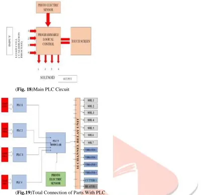
(Fig. 18)Main PLC Circuit(Fig.19)Total Connection of Parts With PLC
This is the main setup of PLC circuit network by which new modified parts are working. In this input is given as load cell and output given as any real value from solenoid. To make sure that this final input and output work in a specific direction a photo electric sensor is joined with PLC Circuit. The photo electric sensor scan only black color of empty pouch. For controlling the whole PLC circuit one touch screen panel is attached.
Fig shows full description of PLC network circuit. The load cell is give input to the PLC network circuit. After that small PLC. Circuit joined with main PLC circuit. This main PLC circuit work as modular.
Photo electric sensor is attached with main circuit so it work in a specific direction which work by scanning black color of empty pouch. Now this modular is joined with a specific relay unit.
This relay unit has 16 channels in which 13 channels joined without put and other connection for extra work. Which doesn’t give any kind of output.
Relay unit joined with 13 different output in which 7 are solenoid which works in different internal parts of machine. 4 vibraters s are joined with output 1 with cutter and 1 with heater.
By this way the PLC circuit joined with all parts of machine which is a parts of modification
For running this network circuit one logical control unit is placed and this attached with the software. We can make changes by joining logical control unit with a computer.
IJEDR1602293
International Journal of Engineering Development and Research (www.ijedr.org)1647
(Fig. 20) screen 1This is a screen 1 showing a communication setting, which will be directly connected with PLC circuit.
It will be covered type choice, characteristic value and measurement time. It also covered Station address, data length, Band rate, Parity, Transfer mode, Stop Bit.
(Fig. 21) screen 2
It is cover all process parameters such as Gross /net , tare weight average time , maximum weight, decimal place, unit of measurement, stand still time, stand still range, zero band, filter ratio.
(Fig. 22) screen 3
IJEDR1602293
International Journal of Engineering Development and Research (www.ijedr.org)1648
(Fig. 23) screen 4.It will be cover an errors of machine. It also cover weight value and status flag.
In statues flag cover zero weight means empty, max. weight means overload, stable measured value.
The error flag work when error consider in a machine.It cover power supply abnormality, hard ware abnormality. When error in anyone channel then it cover Sen voltage error and conversion error.
Final Fabrication:
(Fig. 24)Main Component of Machine 1
IJEDR1602293
International Journal of Engineering Development and Research (www.ijedr.org)1649
(Fig. 26) Main Component of Machine 3(Fig. 27)Touch Screen for Control the Machine
IJEDR1602293
International Journal of Engineering Development and Research (www.ijedr.org)1650
(Fig. 29)Controller of Plc. Circuit(Fig. 30)Relay Channel unit
It is Fully automatic Plastic Pouch packaging machine. It will be directly control by PLC (Programmable Logic Controller).In use of PLC circuit 16 relay channel unit will be connected with all parts of Automatic plastic pouch packaging machine. The final fbrication will be shown in Fig.
Cost Analysis:
COST ANALYSIS TABLE WITH SINGLE OUTPUT
Sr. No. PART NAME MODEL NO. NUMBER OF PARTS RATE OF EACH PART in Rs. COST[Material + Fabrication] in Rs.
1 Hopper A 5132 1 8000 8000
2 Hopper
support B 5145 2 5500 11000
3 Main
structure B 51451 1 15000 15000
4 Upper gate C 3107 4 700 2800
5
Upper gate bottom part
C 31071 4 945 3780
6 Vibrator E 1611 4 1600 6400
7 Vibrator
stand B 51452 4 2000 8000
8 Load cell
stand B 51453 4 2020 8080
9 Load cell L 5545 4 1500 6000
10 Bowl for
material D 2901 4 1160 4640
11
Bowl bottom part
D 29012 4 880 3520
12 Pneumatic
IJEDR1602293
International Journal of Engineering Development and Research (www.ijedr.org)1651
19 Heater HTY
7876 2 10000 20000
20 Air
compressor 1 45000 45000
21 TOTAL 379630
Conclusion and Results
The PLC controller control by the various plc. programming software. It will cover all the process parameters of automatic plastic pouch packaging machine. Weight base plate and photo electric proximity sensors were added in the existing design of the machine. Inclusion of Weight base plate increased the productivity by 10% and with help of Proximity sensors the rejection rate of the plastic pouch has been decreased. The existing design of the machine has single out put against four inputs. Further change in the design can be made such that the number of inputs equal the number of outputs by using the same number of sensors. References
1. D. H. Youngman Design For High SPEED PACKING MACHINE 1964
2. Yuming Lu , Yingui Liu , Gengyu Li, Guozhi Song Mingzhe Liu Weixin Liu DESIGN AND APPLICATION OF AN AUTOMATIC PACKING MACHINE CONTROLLER BASED ON ATmega 128.(978-1-4244-5586-7/10)
3. NeilBrown,DavidKerr,RobertM.Parkin ,MichaelR.Jackson,FangminShi Non-contact laser sealing of thin polyester food packaging films 50(2012)1466-1473.
4. Xiao SUN, Hao ZHOU, Xiangjiang LU, Yongbin LIU Research of control System Of Packing Machine on PLC Vol.11 No.6 ,june 2013,pp3060-3065.
5. Shashank Lingappa m ,Vijayavithal Bangale, Sreerajendra PLC Controlled Low Cost Automatic Packing Machine 2250-3234 volume 4 ,Number 7(2014),pp 803-811.
6. Nitaigour Premchand Mahalik Advaces in Packaging Methods , Processes and Systems.2014,5,374-389;doi:10.3390/challe5020374
7. Joanna Marie M. Baroro, Melchizedek I. Alipio, Teodoro M. Ricamara, Angelo A. Beltran Jr. Automation of Packaging and Material Handling.
8. Using Programmable Logic Controller Volume No3 ,Issue No,6 pp:767-770.