CSEIT1724170 | Received : 10 August 2017 | Accepted : 21 August 2017 | July-August-2017 [(2)4: 645-650]
International Journal of Scientific Research in Computer Science, Engineering and Information Technology © 2017 IJSRCSEIT | Volume 2 | Issue 4 | ISSN : 2456-3307
645
Reducing Memory Consumption of UART With Linear
Feedback Shift Register
Simarjeet Singh
*,
Amandeep Kaur
Department of ECE, University College of Engineering, Punjabi university Patiala, Punjab, India
ABSTRACT
In Parallel communication increase the complexity of system by increase the Circuit Signal complexity.But in serial communication signal distortion is increased. So improve the serial communication in UART by given Signal feedback.In this paper proposed LFSR register in UART communication which reduce memory usage as compare to existing method.
Keywords: UART, Serial Communication, Parallel Communication, LFSR
I.
INTRODUCTION
To meet the current operation microcontroller and digital signal processor require coveted framework execution. Be that as it may, in real process, it is extremely troublesome to accomplish sought outcome, since it relies upon different factors. Communication is imperative factor which influence the execution of framework. A universal asynchronous receive/transmit (UART) is an incorporated circuit which plays the most critical part in serial communication. It handles the change amongst serial and parallel data. Serial communication decreases the bending of a signal, in this way makes data transfer between two frameworks isolated in incredible separation conceivable. It contains a parallel-to serial converter for data transmitted from the computer and a serial to parallel converter for data coming in by means of the serial line. The UART likewise has a buffer for incidentally putting away data from rapid transmissions. Notwithstanding the essential employment of changing over data from parallel to serial for transmission and from serial to parallel on gathering, a UART will ordinarily give extra circuits to signals that can be utilized to show the condition of the transmission media and to control the stream of data in the occasion that the remote gadget is not set up to acknowledge more data. UART must have a bigger interior buffer to store data originating from the modem until the CPU
has room schedule-wise to process it. The UART serial correspondence module is isolated into three sub modules: the baud rate generator, receiver module furthermore, transmitter module Therefore, the usage of the UART correspondence module is really the acknowledgment of the three sub-modules. The baud rate generator is utilized to deliver a neighbourhood clock flag which is substantially higher than the baud rate to control the UART get and transmit; The UART receiver module is utilized to get the serial signals at RXD, and change over them into parallel data; The UART transmit module changes over the bytes into serial bits as per the essential frame format and transmits those bits through TXD [1].
II.
METHODS AND MATERIAL
A. UART Transmission Protocol
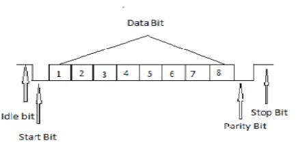
information are sent, with the Least Significant Bit (LSB) being sent first into synchronization with the check in the transmitter. At the point when the whole information word has been sent, the transmitter may include a Parity Bit that the transmitter generates. The Parity Bit might be utilized by the collector to perform straightforward error checking. At that point no less than one Stop Bit is sent by the transmitter. On the off chance that inaccurately arranged information is gotten, the UART may flag a framing error. On the off chance that another byte is gotten before the past one is perused, the UART will flag an overrun error.
Figure 1. UART Frame Format
B. Applications of UART:
1. Transmitting and accepting UARTs must be set for a similar bit speed, character length, parity, and stop bits for legitimate operation. The accepting UART may recognize some confounded settings and set a “framing error” signal bit for the host framework; in uncommon cases the getting UART will create an inconsistent stream of disfigured characters and exchange them to the host framework.
2. Typical serial ports utilized with PCs associated with modems utilize eight data bits, no parity, and one stop bit; for this setup the quantity of ASCII characters every second equivalents the bit rate separated by 10.
3. Some ease home PCs or embedded systems abstain from a UART and utilize the CPU to test the condition of an information port or specifically control a yield port for data transmission. While extremely CPU-serious (since the CPU timing is basic), the UART chip can in this way be overlooked, sparing cash and space. The method is known as bit-banging.
C. Literature Review
Surya Tejeswari Yeturi et.al. [2] This paper concentrates on the TRA (test response 646nalysed), circuit of BIST, in this paper, in past outline TRA contrasts the outcomes and ROM values, proposed configuration executed with basic MISR circuit. The recreation result execution accomplished by BIST empowered UART design through VHDL writing computer programs is sufficient to repay the additional equipment required in the BIST engineering. This strategy create arbitrary test design naturally, so it can give less test time contrasted with a remotely connected test example and accomplishes considerably more efficiency toward the end.
G. Srilatha et.al. [3] All inclusive Asynchronous Receiver and Transmitter (UART) with BIST ability has the targets of testing the UART on chip itself and no outside gadgets are required to play out the test. This paper concentrates on the VERILOG usage of UART with BIST ability utilizing SOC innovation. This paper displays the design of UART with BIST which tests the UART for its right capacity. The entire outline is reproduced in rhythm IUS and integrated utilizing RTL compiler and executed on SOC experience.
Mohd Yamani Idnaldris et.al. [4] To expand unwavering quality, makers must be ready to find a high rate of faulty chips amid their testing systems. This paper will highlight the consideration given by most clients who are anticipating the originator to incorporate testability includes that will increment their item unwavering quality. This paper concentrates on the plan of a UART chip with implanted Built-In-Self- Test (BIST) engineering utilizing FPGA innovation. The paper begins by depicting the conduct of UART circuit utilizing VHISC Hardware Description Language (VHDL). In the usage stage, the BlST method will be consolidated into the UART plan before the by and large configuration is blended by methods for reconfiguring the existing plan to match testability necessities.
full testability are interested in the increased plausibility of item disappointments and missed market openings. Likewise, there is a need to guarantee the data exchange is blunder verification. This paper focuses on the introduction of Built-in self-test (BIST) and Status register to UART, to conquer the over two constraints of testability and data integrity. The 8-bit UART with status register and BIST module is coded in Verilog HDL and integrated and reproduced using Xilinx XST and Isim rendition 14.4 and acknowledged on FPGA. The outcomes indicate that this model eliminates the requirement for higher end, costly testers and accordingly it can lessen the improvement time and cost.
Mohd Yamani IdnaIdris et.al.[6] The expanding development of sub-micron technology has brought about the trouble of testing. Outline and test engineers have no decision however to acknowledge new obligations that had been performed by gatherings of experts in the earlier years. Configuration engineers who don’t outline frameworks in light of full testability open themselves to the expanded probability of item disappointments and missed market openings. BIST is an outline method that enables a circuit to test itself. In this paper, the test execution accomplished with the usage of BIST is ended up being sufficient to balance the disincentive of the equipment overhead delivered by the extra BIST circuit. The method can give shorter test time contrasted with a remotely connected test and permits the utilization of minimal effort test gear amid all phases of generation.
Shivshankar Mishra et.al. [7] This paper concentrate on the usage of configurable linear feedback shift register (CLFSR) in VHDL and assesses its execution as for rationale, speed and memory prerequisite in FPGA. Behavioral execution of CLFSR in VHDL is configurable in wording of number of bits in the LFSR, the quantity of taps, positions of each tap in the shift register stage and seed estimation of LFSR. The objective gadget utilized for execution of CLFSR is Xilinx Virtex-4 FPGA. For 647nalysed647d647t and amalgamation of CLFSR Xilinx ISE 9.2i instrument is utilized. The yield waveforms what’s more, timing report are additionally talked about.
Shumit Saha et.al. [8] With the quick development of Integrated Circuits (Ics) innovation, the many-sided quality of the circuits has likewise increased. Therefore,
the many-sided quality of the circuit requests self-testability in equipment to moderate the item disappointment. Worked in-self-test (BIST) is such a procedure which can take care of the demand of self-testability with a successful arrangement over expensive circuit testing framework. This paper speaks to designing and execution of a Universal Asynchronous Receiver Transmitter (UART) with self-testing capacity. So as to attain reduced, steady and solid information transmission, the UART is planned with Verilog HDL language and orchestrated on Spartan2 FPGA. Here, the Baud Rate of the UART is 4 Mbps. This UART likewise uses the RS-422 standard.
Shruti Hathwalia et.al. [9] This paper proposes a 32 Bit Linear Feedback Shift Register which creates pseudo-irregular test designs as the input bit is a straight capacity of its past state. The aggregate number of irregular state produced on LFSR depends on the input polynomial. As it is basic counter so it can tally greatest of 2n – 1 by utilizing most extreme input polynomial. Here in this paper we executed 32-bit LFSR on FPGA by utilizing VHDL to concentrate the execution and investigation the conduct of arbitrariness. The examination is yielded out to discover number of doors, memory and speed prerequisite in FPGA as the quantity of bits is expanded. Likewise, the recreation issue for long piece LFSR on FPGA is introduced. The outline is 647nalysed647d and orchestrated in Xilinx 14.5 ISE and Model Sim 10.1b.
Chien-In Henry Chen et.al. [11] A configurable two-dimensional (2-D) LFSR based test generator and an automated combination system are exhibited. Without storage of test patterns, a 2-D LFSR based test pattern generator can generate a succession of precomputed test patterns (identifying random-pattern-resistant faults) and took after by random patterns (identifying random-pattern-detectable faults). The hardware overhead is decreased considerably through configuration. The configurable 2-D LFSR test generator can be adopted in two basic BIST execution options: test-per-clock (parallel BIST) and test-per-scan (serial BIST). Experimental consequences of per-clock and test-per-scan BIST of benchmark circuits demonstrate the viability of the proposed method. The configurable 2-D LSFR can also be adopted in chip-level and system-on-a-chip (SoC) BIST.
Chao Cheng et.al. [12] This paper proposes an enhanced three-stage LFSR design with both higher equipment productivity and speed. Generator polynomials for the to begin with and third steps are built with iterative little length polynomials, which can thus be effortlessly dealt with by proposed look-ahead pipelining algorithm. Another plan is additionally proposed for chopping down the emphasis bound of the LFSR structure in the second step. This design can be connected to any LFSR structure for rapid parallel usage. For instance, for the parallel BCH (8191, 7684) encoder with various unfurling variables J from 8 to 32, the proposed configuration can accomplish speedup of 2.83% to 15.78% and XOR doors investment funds of 9.67% to 26.28%.
CHIEN-IN HENRY CHEN et.al. [13] A BIST plot in light of a configurable 2-D LFSR and a method to plan a test design generator have been introduced. Without capacity of test examples and seeds, the 2-D LFSR test design generator can produce a grouping of deterministic test designs and additionally pseudo-random examples. The equipment overhead of this BIST plot diminished impressively through design. The analysis result demonstrates that contrasted and the non-configurable 2-D LFSR, the quantity of flip-lemon is decreased by 79% for five incorporated circuits. The normal number of shortcomings distinguished by the configurable 2-D LFSR is 9.27% higher than that of the traditional LFSR and 0.57% higher than that of the non-configurable 2-D LFSR.
J. Norhuzaimin et.al. [14] This paper concentrates on the outline of High Speed UART. The paper begins by portraying the conduct of UART circuit utilizing VHDL. In the outcome also, reproduction part, this paper will concentrate on the bit blunders discovery. Plus, in the Baud Rate Generator part, the Baud Rate Generator is incorporated into the UART plan before the general outline is incorporated. In the Synthesizing part, the VHDL depiction was converted into a circuit graph. VHDL Synthesis is for high unwavering quality frameworks. The reproduced waveform is finished in 0.395 us (baud rate of 20.2532 Mbps), 19.2 us (baud rate of 416.6667 kbps), 211.2 us (baud rate of 37.8787 kbps) and 1.6448 us (baud rate of 4.8638 kbps) utilizing 20 MHz clock cycle. The reproduced waveforms in this paper have demonstrated the unwavering quality of the VHDL usage to depict the qualities and the engineering of the outline UART with baud rate generator.
P. Rajee Priyanka et.al. [15] This venture concentrates on the execution of UART with status register utilizing multi bit flip-flop. The serial specialized gadget utilized as a part of this venture is UART. A UART (Universal Asynchronous Receiver and Transmitter) is a gadget permitting the gathering and transmission of data, in a serial and asynchronous way. So the cost and intricacy can be diminished. Multi-bit flip-flop is a compelling force sparing usage philosophy by blending single piece flip-flops in the outline. Multi-bit flip-flops can lessen clock dynamic power and the aggregate flip-flop range successfully.
III. RESULTS AND DISCUSSION
Figure 4.2 Memory of Proposed work
Table 4.1 Comparison of memory between existing method and proposed method:
Figure 4.3 Comparison of memory between existing method and proposed method
IV.CONCLUSION
In describe architecture of UART that support feedback signal distortion by LFSR register instead of serial VenkateswarluRapalli. "Design of BIST Enabled
UART with MISR." International Journal 85 (2015).
[3]. Srilatha, G., D. Kavitha, and G. Sanath Kumar. "Implementation of UART with BIST Technique in System-on-Chip (SOC)." International Journal of Emerging Technology and Advanced Engineering (IJERAE), ISSN: 2250-2459. [4]. Idris, Mohd Yamani Idna, and MashkuriYaacob.
"A VHDL implementation of BIST technique in UART design." TENCon 2003.Conference on Convergent Technologies for the Asia-Pacific Region.Vol.4.IEEE, 2003.
[5]. SRILATHA, GOTTE, RAJITHA GULLAPALLI, and G. SANATH KUMAR. "UART Realization with BIST Architecture in FPGA." (2014).
[6]. Idris, Mohd Yamani Idna, MashkuriYaacob, and ZaidiRazak. "A VHDL implementation of UART design with BIST capability." Malaysian Journal of Computer Science 19.1 (2006): 73.
[7]. Mishra, Shivshankar, Ram RackshaTripathi, and Devendra Kr Tripathi. "Implementation of configurable linear feedback shift register in VHDL." Emerging Trends in Electrical Electronics & Sustainable Energy Systems (ICETEESES), International Conference on. IEEE, 2016.
[8]. Saha, Shumit, MdAshikurRahman, and Amit Thakur. "Design and implementation of a BIST embedded high speed RS-422 utilized UART over FPGA." Computing, Communications and Networking Technologies (ICCCNT), 2013 Fourth International Conference on.IEEE, 2013. [9]. Hathwalia, Shruti, and MeenakshiYadav.
"Design and Analysis of a 32 Bit Linear Feedback Shift Register Using VHDL." International Journal of Engineering Research and Applications 4.6 (2014): 99-102.
[10]. Kakar, Shikha, Balwinder Singh, and ArunKhosla. "Implementation of BIST Capability using LFSR Techniques in UART." the proceedings of International Journal of Recent Trends in Engineering 1.3 (2009).
[11]. Chen, C-IH, and Kiran George. "Configurable two-dimensional linear feedback shifter registers for parallel and serial built-in self-test." IEEE transactions on Instrumentation and Measurement 53.4 (2004): 1005-1014.
[12]. Cheng, Chao, and Keshab K. Parhi. "High speed VLSI architecture for general linear feedback
shift register (LFSR) structures." Signals, Systems and Computers, 2009 Conference Record of the Forty-Third Asilomar Conference on.IEEE, 2009.
[13]. Chen, Chien-In Henry, and Yingjie Zhou. "Configurable 2-D linear feedback shift registers for VLSI built-in self-test designs." VLSI Design 11.2 (2000): 149-159.
[14]. Norhuzaimin, J., and H. H. Maimun. "The design of high speed UART." Applied Electromagnetics, 2005.APACE 2005.Asia-Pacific Conference on.IEEE, 2005.