EEMCS/Electrical Engineering
Control Engineering
Wifi interface for mobile robots
Oskar Janssen
Predoctoral assignment
Supervisors: prof.dr.ir. J. van Amerongen dr.ir. J.F. Broenink ir. P. Maljaars
February 2008
Summary
For the post-academic course on real-time software development a game is being devel-oped. This game consists of 8 small robots that play a ballgame together. The main target for these robots is to push several balls into holes in a field as quickly as possible. To play this game the robots are equipped with wheels, sensors, a wireless communication facility and a TS-7400 development board containing an ARM9 embedded processor to control the several hardware components.
The objective of this project is to develop an interface for wireless communication on the TS-7400. This interface will be part of a bigger application that controls the complete robot. It provides a set of functions to the control part of that application.
Before this interface could be implemented more knowledge about the available hardware was gained. Thereafter a communication protocol was designed. This protocol records the possibilities and restrictions of the way of communicating. A set of functions has been designed that can be used by robots to send and receive specific information.
In the resulting design all robots communicate via a referee application that runs on an independent personal computer. This referee application takes care of the control of the game. It registers robots before the start of the game and judges information requests of robots during the game. The referee application itself has an interface that can be controlled by a human. This human referee handles cases that can not be controlled by the referee application (starting the game, determining a winner, etc.).
Samenvatting
Voor het vak real-time software development wordt momenteel een spel ontwikkeld. Dit spel bestaat uit 8 robots die samen een balspel spelen. Het hoofddoel voor deze robots is om zo snel mogelijk enkele ballen in gaten van een speelveld te duwen. Om het spel te kunnen spelen zijn de robots uitgerust met wielen, sensoren, hardware voor draadloze communicatie en een TS-7400 ontwikkelbord. De TS-7400 is uitgerust met een ARM9
processor om de verschillende hardware componenten aan te sturen.
Het doel van dit project is het ontwikkelen van een interface voor draadloze communi-catie op de TS-7400. Deze interface zal deel uit maken van een grotere applicommuni-catie die de gehele robot aanstuurt. Het zal die applicatie voorzien van een verzameling functies. Voordat deze interface ontwikkeld kon worden moest er eerst kennis vergaard worden over de beschikbare hardware. Daarna kon een communicatieprotocol worden ontworpen. Het protocol legt de mogelijkheden en onmogelijkheden van de manier van communiceren vast. Een verzameling functies is ontworpen die door de robots gebruikt kan worden om informatie te verzenden en te ontvangen.
In het ontwikkelde ontwerp communiceren alle robots via eenreferee applicatie die op een onafhankelijke PC draait. Deze referee applicatie controleert het spelverloop. Het reg-istreert robots voor het begin van een spel en beoordeelt informatieaanvragen van robots tijdens het spel. De referee applicatie heeft een interface die bestuurd kan worden door een mens. De menselijke scheidsrechter voert acties uit die niet door de referee applicatie gedaan kunnen worden (het starten van het spel, de winnaar bepalen, etc.).
Contents
3 Software and hardware testing 19 3.1 Integration testing . . . 19
C Preparation of the TS-7400 35 C.1 Bypassing ’fastboot’ . . . 35
C.2 Internet connection via Ethernet . . . 36
C.3 Internet connection via WiFi . . . 36
1
Introduction
1.1 Project overview
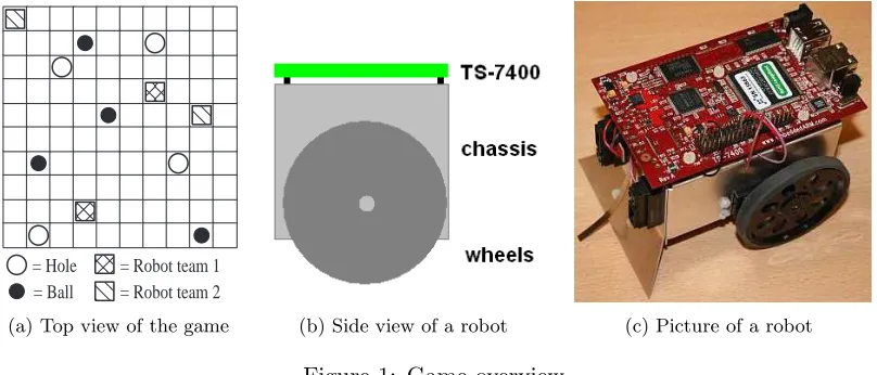
A new training setup has been developed for the course onreal-time software development. In this new setup a ball game will be played with 8 small robots. The game will be played on a board that is divided into small squares. Some of these squares have a hole, others do not. Robots and balls will be placed on some of the empty squares. The robots can de-tect lines with the help of sensors. This way they can calculate their position on the board. The robots have motorized wheels to ride and sensors to determine their position. They are also able to communicate via a wireless connection. All robots carry a development board (TS-7400) that is able to control the hardware.
The robots will be divided into two teams of each 4 robots that play against each other. Each team has to try to push all the balls in the holes as quickly as possible. The team that clears the major part of the balls wins the game. Figure 1a shows a setup of the game (top view). A side view of a robot is shown in figure 1b.
= Hole = Ball
= Robot team 1 = Robot team 2
(a) Top view of the game (b) Side view of a robot (c) Picture of a robot
Figure 1: Game overview
The objective for the students that follow the course is to write control software for these robots in the graphical programming environmentgCSP. gCSP is a graphical design tool suitable for designing and interconnecting parallel processes.
Besides the interface part, referee software has to be designed that applies rules to the game. It informs robots when a new game starts and which robot belongs to which team. The referee will run on a separate PC connected to a WiFi router. The straight lined blocks in figure 2 show the scope of this project. Lower level software (e.g. drivers) and hardware do not belong to the scope of this project.
Control
Figure 2: Scope of this project
1.2 TS-7400 development board
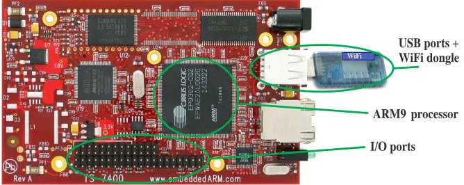
The hardware will be controlled by a commercial available development board, the TS-7400. The board contains a powerful ARM9 processor that is able to run the software. It also contains (flash)memory on which the compiled gCSP application can be stored. Furthermore I/O ports are available which can be used to connect hardware (sensors, motor). Besides the above mentioned properties, this board contains also two USB-ports. One port can be used for a WiFi dongle to create a wireless connection. The manufacturer of the development board provides a driver for the WiFi dongle that works with the TS-7400 board. Figure 3 shows a picture of the board.
USB ports + WiFi dongle
ARM9 processor
I/O ports
WiFi
1.3 Approach of this project
The main target of this project was to create software that enables the use of the WiFi communication on the TS-7400. To accomplish this target an application was written ’on top’ of the available driver of the WiFi dongle. The TCP/IP protocol had been chosen for communication because of its reliability. Socket programming has been used to implement the protocol.
The software structure that has been designed consists of 3 layers. The top layer includes the interface to the control software of the robot while the lower layer is the communica-tion layer (Figure 2). The middle layer is used for data processing.
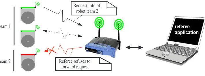
Another objective was to create a referee application that has control over communica-tion during the game. This referee applicacommunica-tion has been designed in the same way as the robot software to make use of classes that already had been written for the robot software. The chosen setup only allows communication between a robot and the referee. Although more robots can communicate with the referee at the same time. By choosing this setup the referee can easily protect robots against cheaters that are trying to steal data. A drawback of this approach is the fact that most of the data has to be send twice (robot x
→ referee → robot y). Figure 4 shows this idea. The referee decides whether or not the
request will be honored. By example, if the first robot from team 1 wants data from a member of team 2, this request will be denied by the referee (in other words: the referee will not forward the request).
During development the software had to be tested. The first tests were performed locally on a laptop. One window to simulate a robot and one to execute the referee application. After some successful tests a cross compiler was used to compile the software for the TS-7400 board. That way the software could be tested on a board that will be placed on a robot. Settings have been figured out to make the TS-7400 automatically connect to a wireless router and run its software.
team 1
team 2 Referee refuses to
forward request Request info of
robot team 2
1.4 Organization of the report
2
Software development
The source code of the software is written in C++. C++ is an object oriented language that is also used in the ’CT library’ (a library where gCSP generates code for). This chapter will explain how the software is designed. First of all the design process will be discussed. Thereafter the structure of the written software will be explained, followed by the behavior of the written software.
2.1 Design process
2.1.1 Requirements
Two team of 4 robots have to play a ball game on a field (size: approximately 2 x 2 me-ter). Each team has to clear several balls on the field by pushing them into holes. Wireless communication must be possible among robots of the same team, but not between dif-ferent teams. Communication consists of commands (short strings) that provide robots of the same team with each other’s information. This information consists of: position,
orientation,destination and motion. This way the robots can develop a strategy to clear the field as quickly as possible. A separate, neutral application (the referee) has overall control of the game. It is operated by a human to start and stop the game.
From the text above the following requirements can be filtered for the robot software:
• Interface to thecontrol part (see fig. 2) containing a set of commands for information
requests.
• The ability to provide information to robots of the same team. • Avoid sending information to other robots.
• Communication with the referee application.
The requirements for the referee application are:
• User interface to human referee.
• The ability to communicate with all robots in the field.
• Keep track of important robot information (which robot belongs to which team). • Provide robots with information about the game (e.g. start/stop).
General requirements are:
• Setup a reliable communication network within a radius of about 5 meters from the
center of the field.
• Robots must be able to communicate at a rate of at least 24 messages per second.
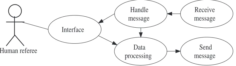
The software requirements can be translated into use cases. Figure 5 shows the use case of the robot software. Sending a message is a straight forward action that has no restrictions with respect to the state of the game or to whom the message is send to. The receiver judges the content of message and creates an answer based on the circumstances. The robot has to do this too when it receives a message.
Robot control
Handle message
Data processing
Receive message
Send message Interface
Message robot
Message referee
Figure 5: Use case diagram of robot software
The use case diagram of the referee is shown in figure 6. The communication cases are identical to the robot, but the referee has to judge incoming messages based on different criteria (depending on the designed communication structure, see following section). Fur-thermore the referees interface is two-way traffic: executing commands from the human referee and updating information on the screen.
Human referee
Handle
message
Data
processing
Receive
message
Send
message
Interface
2.1.2 Communication structure
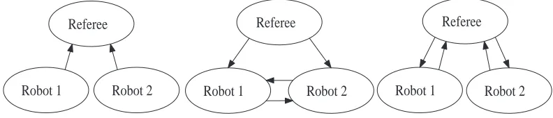
A major choice have to be made about the way of communicating. Figure 7 shows 3 possibilities.
• One-way communication from robot to referee. No communication between robots. • One-way communication from referee to robot. Communication between robots. • Two-way communication between robot and referee. No communication between
robots.
The first option requires the robot to contact the referee at a predefined time interval. A robot can ask the referee if the game has been started or for certain information of robot x. It also has to send its own information to the referee to make sure team mates can gather up-to-date information (via the referee). An advantage of this solution is the simplicity of the communication structure. The robot does not have to worry about incoming requests and leaves this task to the referee. Drawbacks are the communication overhead and the delays caused by this polling approach.
The second option is to allow direct communication among robots. The influence of the referee in this approach is minimized. It only interrupts robots if game settings change. The biggest advantage of this solution is the minimum amount of communication, be-cause messages are directly send to the intended recipient. A drawback is the difficulty to avoid crosstalk between the teams and to make sure the robots obey the rules of the game. The last solution is a combination of the first 2 solutions. Here the referee is situated in the middle while no polling is needed. If a robot wants information from another robot it has to send a message to the referee. The referee decides if the request is honored, and if so, it will forward the message. The robot has only 1 IP address to send messages to and also have to check 1 IP address when receiving a message. This is the address of the referee. This solution needs twice the communication rate of solution 2, but has the safety of solution 1.
Referee
Robot 2 Robot 1
Referee
Robot 2 Robot 1
Referee
Robot 2 Robot 1
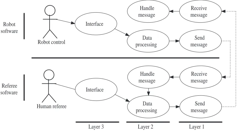
The chosen communication structure is the two-way communication between robot and referee. This one has been chosen because it is a compromise between maximum commu-nication rate and controllability. Figure 8 shows the use case belonging to this solution. For both robot and referee the communication procedures (layer 1) can be exactly the same. The other 2 layers may have common functions, but also specific functions. A dif-ference in the referee use case diagram is the arrow pointing from the Handle message to
Data processing case. This shows that the referee can forward received messages from one robot to another. On the robot side this link does not exists. This means that incoming messages can be handled independently of outgoing messages.
Robot control
Layer 3 Layer 2 Layer 1
Figure 8: Resulting use case diagram matching the chosen communication structure
2.1.3 Communication protocol
The first thing to realize before choosing a communication protocol is to determine what kind of data will be sent. Robots talk because they want to gather information from team mates. With that information they can determine their next move. It is part of their strategy. This information mainly consist of integers (indicating by example the position of a robot). These integers have all values between 0 and 256, they will thus be send as characters. So the messages are relatively short (only a few bytes), but on the other hand it is very important that the recipient receives the message without errors.
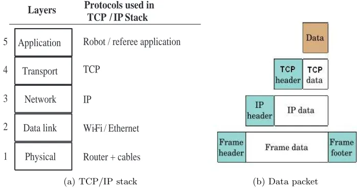
Application
(a) TCP/IP stack (b) Data packet
Figure 9: Data transport through different protocol layers
Figure 9b (Wikipedia IPS, 2007) shows that the layers add headers to the actual data. To calculate the maximum number of packets per second that can be send over the Wi-Fi connection, these header sizes need to be known. The typical sizes of the headers are:
• TCP header: 24 bytes • IP header: 20 bytes • Frame header: 14 bytes • Frame footer: 4 bytes
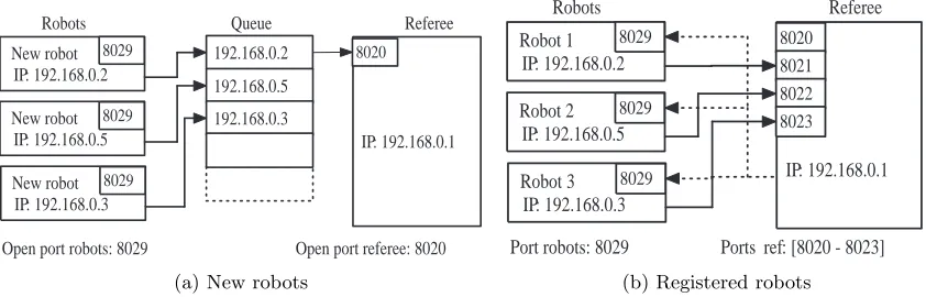
For this project socket programming is used in the following way. First of all the ref-eree application opens a certain port (in this case port 8020, which can be changed) and starts listening to it. When the robot application starts up, it also opens a port where it listens to (by default port 8029). This port can be used by the referee to contact a robot. Both robot and referee can now act either as a host or client.
When a robot contacts the referee for the first time, the referee opens a new port for that robot (in the range 8021-8028 by default). The referee saves its information in a variable. After registration all robots can contact the referee in parallel. If there was only one open port for all the robots they would have to wait in a queue. Figure 10 shows the difference in situation.
All robots have the same port where they listen to, but differ in IP addresses. The referee on the other hand has one IP address but multiple ports. Every unit in the game can thus be contacted by a unique combination of IP address and port number. It is not possible for robots to talk to each other directly, because for every incoming message on the robot side an IP check will verify the sender. If the sender IP is not equal to the referee IP it will discard the message.
Note that the port numbers mentioned before can be changed as long as the ports are not used by other programs (Wikipedia port numbers, 2007). The developed software can handle a maximum of 8 robots. If in the future more robots need to be connected, some small changes have to be made (limits of variables, etc).
New robot
Open port robots: 8029 Open port referee: 8020 IP: 192.168.0.1
Port robots: 8029 Ports ref: [8020 - 8023] 8021 8022 8023
IP: 192.168.0.1
(b) Registered robots
2.1.4 Command set
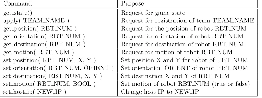
The robot interface consists of a set of functions that can be used for communication. Each function handles a specific parameter of the robot. This set of functions is called the command set. The advantage of such a command set is that other software parts do not have to take care of communication related issues (how to setup a connection etc), it just calls one function with some arguments and gets the information it wants. Table 1 shows the complete list of the implemented functions that can be called. For more details about arguments and return values see Appendix B. This list can easily be extended if more functions are desired.
Command Purpose
get state() Request for game state
apply( TEAM NAME ) Request for registration of team TEAM NAME
get position( RBT NUM ) Request for the position of robot RBT NUM
get orientation( RBT NUM ) Request for orientation of robot RBT NUM
get destination( RBT NUM ) Request for destination of robot RBT NUM
get motion( RBT NUM ) Request for motion of robot RBT NUM
set postition( RBT NUM, X, Y ) Set position X and Y for robot of RBT NUM
set orientation( RBT NUM, ORIENT ) Set orientation ORIENT of robot RBT NUM set destination( RBT NUM, X, Y ) Set destination X and Y of RBT NUM
set motion( RBT NUM, BOOL ) Set motion of robot RBT NUM (true or false)
set host ip( NEW IP ) Change host IP to NEW IP
Table 1: A complete list of the implemented command set
There are several kind of commands. Some commands involve only the referee, like the ’get state’ and ’apply’, while others are aimed at information exchange among robots. Be-sides updating the local settings it is also possible to set some properties of other robots. This extends the possibilities when programming strategy. By example, if there are 4 robots, one leader can be chosen that can overrule other robots actions.
The reply to a request is always a string with a length between 1 and 10 characters, depending on the specific request. It is a combination of characters and numbers that refer to properties and values. Appendix B contains information about the precise syntax.
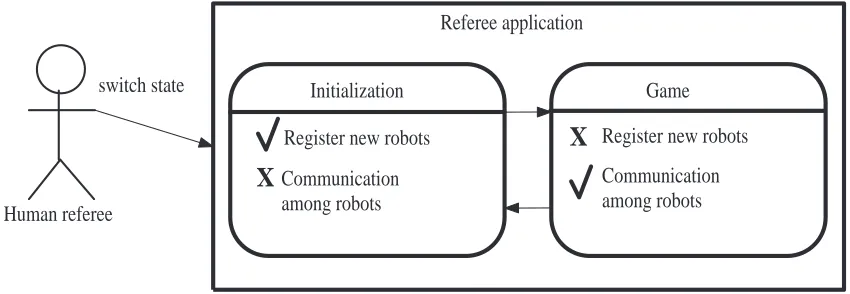
2.1.5 Game states
Human referee
Initialization Game
switch state
Referee application
Register new robots
Communication among robots
X
Communicationamong robots Register new robots
X
Figure 11: State diagram of the referee application
Initialization In the initialization state robots are in principal allowed to sign up for the next game. Enrollment will be denied in the following cases:
• When the maximum of 8 robots has been reached.
• When a team name of more than 8 characters has been chosen.
• When 2 different team names already have been registered and the chosen team
name does not match one of these.
When a registration request is accepted, the referee will save the provided team name and the IP address of the requesting robot. A confirmation will be send along with a registration number for that robot (in range [1 - 8]).
During the initialization state it is not possible for the robots to contact any (possible) teammates, but they are allowed to change their own properties. If a robot has signed up and has updated its local values it has to wait for the referee to change state.
Game The operator of the referee application decides when the enrollment period is over. With the help of the referee interface the game can be started. At this point the state changes togame. All robots that have been registered take part in the game. Other robots cannot take part and have to wait for the next round (at least, they cannot com-municate, but it will not stop them from driving around of course). All registered robots will be notified by the referee on the state change. They also get the subscription numbers of their team mates. Now a robot can simply ask for specific information from another team mate. Such a request is first send to the referee that forwards it to the right robot (assuming it is a legal request). The target robot will send its answer to referee that forwards it again to the robot where the request came from.
2.2 Software structure
2.2.1 Design motivation
From the use case of figure 8 follows that the software of both robot and referee can be divided into 3 layers. They both need an interface and communication layer. In between these layers data processing can take place.
Layer 1: Communication This layer can be the same for both robot and referee. The
layer can be split up into 2 parts (classes): a sending part and a receiving part. The sending part is called client and the receiving partserver. There are standard procedures to implement these parts (Wall, K., 1999).
Layer 2a: Data processing robot On the robot side incoming and outgoing messages
can be handled independently of each other. Each robot has properties (parameters) like position, orientation and so on. These properties must be equal for both outgoing and incoming messages. Therefore a central ’storage’ class has been designed that stores all common variables; the status register. For the outgoing messages a command must be translated into a message (see appendix B). A command listener has been designed to do this. For incoming messages a message handler has been designed. Both classes make use of the status register by either reading or writing data.
Layer 2b: Data processing referee The referee makes also use of a status register.
Although many variables are different in comparison to the robot. E.g. the referee has to store robot IP addresses and team names. The message handler of the referee part is also different. The referee has to do more checks (IP, game state, etc) and call different functions (store robot info, forward message, etc), while the robot message handler only reads or writes data to the status register.
Layer 3: Interface Although both robot and referee make use of an interface, both
interfaces are totally different. The robot interface has more functionality (command set) and returns encoded information. The referee interface on the other hand has less func-tionality but provides more (decoded) information to the human user.
2.2.2 Robot structure
Figure 12 shows the class diagram of the developed robot software. The main task of class
CommandListener is to provide the set of functions shown in table 1. After a function has been called this function verifies the provided parameters (if there are any). If a local variable is requested, the CommandListener will return this value from the StatusRegis-ter class. The StatusRegister contains all (static) information of the robot. Similarly, if a local variable must be updated the CommandListener will update this variable in the StatusRegister. If a function call of the available set is intended for an other robot or the referee, a message will be created by the CommandListener. This message will then be forwarded to the Client class. This class will handle the communication with the referee. The reply of the referee will be returned.
The CommandListener can also be used to do the initial settings (the creation of the a server daemon, an object of class Server that runs as a thread, is part of this) and to execute the shut down routine.
The Server class listens for incoming calls of the referee. When such a call occurs the received message will be forwarded to the MessageHandler class. This class decodes the message so the requested information can be returned or updated. Before the requested action is being executed the MessageHandler first checks the IP address of the sender. This address must be the same as attribute host ip in StatusRegister to make sure that the request came from the referee.
TS-7400
CommandListener StatusRegister
Server MessageHandler Robot main
Client
*
*
*
2.2.3 Referee structure
Figure 13 shows the class diagram of the developed referee software. After the referee application is started an initial server daemon will be started (port 8020 by default, as shown in figure 10). This server can now be used by robots to register for the following game. When the initial server receives an incoming request, the RefereeFunctions class will be called to handle the message. The functionality of this message handler is com-pletely different with respect to the robot message handler, because the referee message handler mainly calls functions instead of returning attribute values. One of these functions is add robot, which adds a new robot to theStatusRegister. The message handle function checks several conditions (see chapter 2.1.5) before a new robot is registered. A registered robot gets its own server daemon and port number. When a request is received on this port the message handler takes care of forwarding it to the right robot (after the request has passed all checks).
On the other side the human user can interact with the referee application. Class UserIn-terface has been written for this purpose. This class provides a text-based interface which can be used to change internal flags or shut down the program.
Computer
RefereeFunctions StatusRegister Server
UserInterface
Referee main
1..8
Client
*
*
*
2.3 Software behavior
This chapter explains the behavior of both software parts. This will be done with the help of sequence diagrams. These diagrams show the major gameflow from a specific point of view (either robot or referee).
2.3.1 Robot behavior
The sequence diagram of the robot behavior is shown in figure 14. The actor on the left-hand side symbolizes the Control software (see figure 8) that will use the developed interface. On the right-hand side the referee actor is drawn. This actor operates on a different platform and is connected via the wireless connection. The numbers on the left-and right-hleft-and side refer to events described in the following text.
When the application is started1
an initialization routine must be called to perform initial settings2
and start the server daemon3
. This server daemon runs in the background and listens to incoming referee requests. When the routine has been finished a message will be returned about the status4
. This message is either ’success’ or ’failure’. If the initialization has been successful the command set can be used5
. Requests that need communication with the referee are encoded to save bandwidth6
. The encoded mes-sage along with IP and port information will be forwarded to the client. The client object will handle the communication with the referee7
. Parallel to the communication a counter will be started to avoid a possible dead lock. This deadlock might take place if something goes wrong during communication. For example, if the server application suddenly shuts down in the middle of a conversation. There are cases where a function of the command set is called while there is no need to communicate. This is often the case when local variables need to be updated. For example, when sensors of the robot detect a new posi-tion, the position variables (Cartesian coordinates) need to be updated. In this case the StatusRegister will be updated locally8
and the command set function returns immediately. When a robot has finished its job it can call a shut down routine to perform a clear exit9
. This routine terminates the server daemon and free declared memory. Besides outgoing requests (from the robot side), there are also incoming requests10
(from the referee side). These will be received in parallel to other requests by the server thread and forwarded to the message handler11
. The message handler verifies the IP address and will return the requested information from the status register12
. If the received IP address is not the same as the address that has been set by the robot itself (via command
CommandList StatusRegister Client
Figure 14: A sequence diagram of the robot software
2.3.2 Referee behavior
The same approach will be used to explain the referee software. The sequence diagram is shown found in figure 15. Now the left-hand side actor is the human that controls the ref-eree application. The right-hand side actor is the robot software as shown in the previous section. The number of robots can change, therefore multiple bars have been drawn for the robot actor.
After starting up the application1
some initial settings need to be performed2
. An initial server daemon is started3
so robots are able to register. Thereafter the user interface is drawn4
. If the update ui flag is set the interface will update itself automatically at a certain interval5
Several settings can be changed with the help of the interface. One of these settings is the game state. When this state is changed6
the StatusRegister will be updated7
and all registered robots will be notified8
. If the state changes toinit all open server daemons, except for the initial daemon, will be terminated9
. The new state will be returned10
. The referee application can be exited by calling a shut down routine that performs a clear exit11
. This routine terminates all open server daemons and frees declared memory. When a request is received12
it will be handled by the message handler in RefereeFunc-tions. In case the new robot needs to be added the StatusRegister will be updated13
and a new server thread will be started14
. In case a robot wants to send a message to another robot this will be done via the client15
. In all cases the requesting robot will receive an answer16
3
Software and hardware testing
During the development of the software, tests have to be performed to be sure of a proper behavior. One intermediate test has been performed with the server and client classes to ensure the core of the software was working correctly. After this test the robot software and referee software could be debugged mostly independent of each other’s functions. Finally some tests have been executed to measure the performance of the software.
3.1 Integration testing
The Client and Server classes have been tested together to verify a proper working. The set-up for the first test also included the CommandListener class and the RobotMain to keep the intended software structure. In this test the robot sends a certain message to the referee software by calling a command from the implemented command set. The string created by the CommandListener will be forwarded to the client. The client prints the created message as an intermediate check and sends it to the referee server. When the server has received the string, it prints the string to the screen and returns a (different) answer. This answer is also printed to the screen. Figure 16 shows the involved classes in the test and their functions. For a full class diagrams see figures 12 and 13 in chapter 2.2.
RobotMain
Figure 16: Classes involved in the communication test and their functions
This test has been executed on one computer, using the local loop back. Besides a correct transmission of the string, a couple of other aspects have been tested. One of the experi-ments involved a ’disappearing’ referee. Hereby the referee is started and the robot tries to connect to the referee. This succeeds and the robot sends its request to the referee. The referee application receives the message, but instead of sending a reply it shuts down. It appeared that the client waits ’forever’ in this case (deadlock situation) while there is no possibility to set a time-out. To solve this problem, the communication routine has been placed in a separate thread. The main thread starts a counter in parallel that causes a time-out if the sending thread does not return in time. To check whether the sending thread has successfully finished its job the message buffer is checked once in a while. It will be overwritten with the return answer of the server.
3.2 Hardware testing
During the development process most of the tests were performed locally on one computer. The applications were executed in separate windows. This way the communication could be checked easily without a real network connection. When the software development be-came in its final stage tests with a real ’robot’ (development board) were also performed. Because the development board had a different system architecture in comparison with the computer on which the software had been designed, it needed to be compiled with a cross compiler. The cross compiler was already developed by the manufacturer of the development board and could be downloaded and used for free.
With the help of manuals (Technologic systems, 2006 and Technologic systems, 2007) and online support (TS-7000 user group, 2007) the development board could be properly configured for the WiFi connection. Appendix C has been written to summarize this pro-cedure.
The WiFi connection seemed to be pretty weak. A proper connection could be made within a range of about 10 meters from the router, without obstacles in the path of the signal. At a larger distance the connection seemed to be unreliable. This problem had nothing to do with the written software. The problem also showed up with a different router and different (transmission power) settings. It is likely that the used USB dongle can handle more, because it is able to detect routers in a much larger range (about 50 meters). Another problem that showed up during the rate tests (see next section) were the transmission interruptions that sometimes took place. That is, when a robot tries to communicate as quickly as possible the stream of data might be interrupted for a while. The cause of this problem was not found due to the lack of time. A workaround for this problem is to fine tune the timer that prevents the client from a deadlock (as mentioned before). If this timer is set to a value slightly above the average time that is needed for transmission of 1 request (and answer) the highest possible performance can be achieved. The deadlock timer should be set to about 10 to 15 ms. This can be concluded from test results in the next section (table 2).
3.3 Communication rate testing
Not only reliable information exchange is important, but also the rate that can be achieved. To test this rate, a table has been set up to test different parameters that might influence the communication rate. One question is if the amount of bytes in a message influences the rate significantly. By default a message contains 10 bytes, so that length, half the length and double the length has been taken as parameters.
Finally the number of robots has been taken into account. This test shows the differ-ence between the performance of the development board and the computer on which the referee runs.
3.3.1 Single robot tests
The test setup is shown in figure 17. The referee runs on a laptop that is connected to a WiFi router by an Ethernet cable. The test robot is connected to the router by a wireless connection. In practice this setup is realistic, because the robot will automatically connect to the router and start up its application.
However, in this test situation it is not practical to reset the robot after each test. There-fore an extra connection had to be made to start and stop the application on the robot side. A serial connection has been chosen because it does not influence the test process. Another alternative was to use telnet via WiFi. This has been used during later tests. A restriction during the tests was that no messages should be printed to the screen, since that takes a significant amount of time.
Ethernet Wi-Fi
RS 232
Figure 17: Setup of the rate test
Robot
software Start application
Apply to game
Request
Referee Software Referee control
window
Stop application Start application
Robot control window
Print registered robot to screen Change state to 'Game' Notify robot of state change
Reply Print time stamp 1
Print time stamp 2
Application terminates
1000 requests and replies will be send before 2nd time stamp TS-7400 Computer
Figure 18: Sequence diagram of single robot tests
The results of the test can be found in table 2. Test 11, 12 and 13 are exceptions to the explained sequence diagram. In these tests the referee will forward the message to the robot. The robot asks in this case for a parameter of itself via the referee. The second row of the table contains L1, L2 and L3. These abbreviations refer to different layers in the software. Layer 1 consists of the client and server classes. layer 2 includes data processing functions and layer 3 user I/O. On the robot side layer 3 is only a call to a function in layer 2, while at the referee side layer 3 includes updating the user interface (output to screen). These different layers have been taken into account to estimate the amount of time needed by a certain part of the (communication) process.
Test# Robot Referee Message size (bytes) Time (msec / request)
L3 L2 L1 L1 L2 L3 5 10 20
1 X X X 20
2 X X X 20
3 X X X 20
4 X X X 24
5 X X X 8
6 X X X 9
7 X X X 9
8 X X X 9
9 X X X 9
10 X X X 9
11 X X X 29
12 X X X 30
13 X X X 30
Table 2: Communication rate test results of a single robot
3.3.2 Conclusions single robot tests
The first conclusion that can be drawn from table 2 is that the size of the message buffer is a negligible parameter. This is e.g. shown by the results of test 1, 2 and 3: there is nearly a difference in time between them. Other grouped tests where only the buffer size differs support this conclusion. This conclusion agrees with the fact that the message buffer is only a small part of the total packet size.
Test 4 shows the influence of continuously updating the referee interface (update of the screen after each event). This costs 4 ms per request. In the latest version of the software, interface updating is no longer event dependent. A timer can now be set to change the update interval. Due to this modification, the update delay can be neglected (if one sets the timer to approximately 1 second).
Tests [5-7] show that communication takes about 45% of the time to send a request and receive an answer (see the difference in time between tests [5-7] and [1-3]). This amount of time is a result of the TCP / IP protocol. Ensuring error free communication costs time. Especially the handshake procedure that takes place before each send cycle con-sumes plenty time.
Tests [11-13] in comparison with tests [1-3] show that a request send by the referee takes less time than a request send by a robot. Theoretically the time needed for one request should be doubled, because the referee forwards a message (see figure 19). The explana-tion for this time difference is again that the referee runs on a much quicker machine than the robot.
Client Robot
Server Robot
Server Referee
Client Referee Request
Forward request TS-7400 (200 MHz) Computer (2 GHz)
Figure 19: Message flow in tests 11, 12 and 13
The conclusions with respect to time consuming tasks have been visualized in figure 20. The shown tasks match certain parts of the message flow:
• Robot data processing: All data processing in robot software except communication
routines.
• Sending message robot→referee: Time needed to start a Client thread, send a
mes-sage and receive an answer on the robot side. This time does not include data processing on the referee side.
• Forwarding message referee→robot: Time needed to start a Client thread, send a
message and receive an answer on the referee side. This time also includes data processing on the referee side.
This makes clear that the slowest parts of a communication cycle are the data processing of the robot and the wireless communication.
Major time consuming tasks
34% 32%
34%
Robot data processing
Sending message robot => referee
Forwarding message referee => robot
3.3.3 Multiple robot tests
Another similar test has been performed with more than 1 robot. In this test the message size has been set to the default size of 10 bytes. All layers, except for layer 3 at the referee side were involved in this test (that is, all functionality without printing to the screen). Parameters in this test were the number of robots (R1, R2 and R3) that took part and the kind of message they sent. Illegal requests means that the robots requested information of a nonexistent robot, whileLegal requests means that they asked information of each other (all robots are team mates of each other). The results can be found in table 3. An ’X’ indicates that a robot took part in the test. In case of 1 robot it asked for its own data via the referee application. In case of 3 robots they communicated in a ’circle’ (R1→R2,
R2→R3 and R3→R1).
Test# Illegal requests Legal requests Time (msec / request)
R1 R2 R3 R1 R2 R3
1 X 20
2 X X 20
3 X X X 20
4 X 30
5 X X 30
6 X X X 30
Table 3: Communication rate test results of multiple robots
3.3.4 Conclusions multiple robot tests
A surprising result of this test is the fact that the number of robots (smaller than 3) does not influence the time needed for a single request from a robot. This underlines the dif-ference between the power of the computer and the TS-7400. It appears that the referee is still not using its full capacity when 3 robots are communicating as quickly as possible. Unfortunately, due to the lack of available hardware, it was not possible to do this test with all 8 robots.
4
Conclusions and recommendations
4.1 Conclusions
The software works as expected and is reliable if the robots are within a range of about 10 meters from the router. Outside this range, or when obstacles are in the way, robots may have problems with (automatically) connecting to the router.
From the rate tests it can be concluded that the communication rate is lower than ex-pected. Reasons for this lower rate is the fact that a TS-7400 has not the same processing power as an average PC. Especially the communication part of the robot software is a bottleneck that decreases the overall performance.
The maximum speed that can be achieved is about 33 messages per second per robot (assuming legal information requests). This rate is independent of the number of robots if that number is 3 or less. Future tests must show how the rate holds for a game with 8 robots.
All requirements mentioned in section 2.1.1 have been met, so it is likely that the game can be played successfully (without communication being a bottleneck). In case the munication rate becomes a bottleneck due to the increasing number of robots, the com-munication part of the robot software can be improved (see recommendations).
4.2 Recommendations
Since all minimum requirements have been met it is recommended to build all hard- and software for the game. The software created in this project can then be used and tested in practice.
To improve the performance, the way of communicating has to be investigated. The main bottleneck can be solved by eliminating the time consuming actions that now take place every communication cycle. There is probably a smart way to replace the deadlock timer in the Client class. This avoids the creation of a thread for every message to be sent. Another time saving solution might be the combination of commands. Sending 1 long message containing all properties of 1 robot is quicker than sending 4 small messages containing separate properties.
A
Socket programming
The method that was used for implementing the TCP/IP protocol in C++ is calledsocket programming (Wall, 1999). A socket is a data communication channel. Once two processes are connected through a socket, they use a socket descriptor to read and write data to the socket. A connection can be established by the following steps. These steps are shown in figure 21.
Figure 21: The way socket programming works
The names in the figure refer to the functions that has to be called in library socket.h. The first function for both server and client is the socket constructor call. The socket system call needs three arguments:
• domain • type • protocol
For domain the AF INET argument is used; a set of Internet protocols. For the type
The bind function associates a process with a socket. Bind is usually used in server processes to set up a socket for incoming client connections. The arguments to the bind system function are:
• socket descriptor • socket address • address length
The first argument to bind is the socket descriptor created in the previous step. The second argument is a structure containing information about address family (previously mentioned AF INET), a protocol address (IP address) and the port number that should be opened. In the case of the host, the protocol address will be ’any address’. The third argument is the length of the socket address structure.
After a socket is created and associated to a process with bind, a server-type process can call the listen function to listen for incoming socket connections. The arguments to the listen system call are:
• socket
• input queue size
The first argument to listen is again the socket descriptor. The second argument sets the incoming queue size. This is the number of incoming connections that can not be served immediately and have to wait in line. If the line is full, all other incoming calls will be refused. For this project a queue of 8 will be enough (the maximum number of robots). This line is only used when new robots want to subscribe for the next game (see chapter 2).
The connect system call is used to connect a local socket to a remote service. This
function will is only used by the client to contact the server. The arguments are the same as of bind. There is a difference in the socket address structure, which will now contain a specific IP address of the host (instead of ’any address’).
The recv function is used to receive messages from a connected socket. This function is used at both host and client side. The arguments to recv are:
• socket • buffer • buffer length • flags
The socket defined by the first argument must have already been connected to a port using connect. The second argument is a pointer to a block of memory where a received message will be stored. The third argument specifies the size (in bytes) of the reserved memory block. The fourth argument indicates operation flags, but these are not interesting for this project.
B
Commands and messages
This appendix is about the command set and message encoding. The command set and possible answers to the commands are discussed as well as reply and error messages.
B.1 Message encoding
When a command is called from ’outside’, the corresponding function in the class Command-Listener will call the generalfill buffer function. It includes a unique letter as an argument that represents the specific command. Other arguments containing target robot number, position information, etcetera may also passed to the fill buffer function. This function creates the string (message) that is shown at the bottom of figure 22. Slots that are not used will be filled with dashes.
When an argument is an integer, it will be translated to an ASCII integer (e.g. int 1
→ ASCII 49 or ’1’). Integers bigger than 9 will be translated to two ASCII symbols (e.g.
int 39 → ASCII ’3’ ’9’). Integers bigger than 99 are not allowed.
This method seems to be a bit inefficient, but if the available bandwidth and enormous amount of overhead (only about 15 % of the communicated bytes are data, see chapter 2) are taken into account a couple of bytes more or less does not really influence the perfor-mance. On the other hand ASCII makes the messages readable, which is a big advantage for debugging purposes. The host side also knows that it can always expect 10 bytes of data, no matter what the content is. But even if these extra bytes are unwanted, a sim-ple setting in the header file can decrease the buffer size. Other functions will still work with the 10 bytes buffer, but the slowest part is still the wireless communication, not the processing software.
P
2
-
-
-
-
-
-
-
-Function call
get_position(2);
Byte:
1
2
3
4
5
6
7
8
9
10
Command
Destination
Parameter 1
Parameter 2
Parameter 3
Parameter 4
Parameter 5
Parameter 6
Parameter 7
Parameter 8
B.2 Command set
Table 4 below shows an overview of the implemented commands. The arguments between the parenthesis are just dummy values. The first argument, if there is any, always repre-sents the target robot number (except for the apply and set host ip functions that need a string). A zero value means a local setting or request, so in the table below the orien-tation of the robot itself would be set to 3 if the command was called with these parameters. The values of the parameters should be within certain bounds:
• target robot number: [0 - 8] (local + team mates)
• position and destination: [0 - 99] [0 - 99] (x and y coordinates) • orientation: [0 - 3] (directions of the wind)
• motion: [0 - 1] (stop and move)
• apply: [a-z, A-Z and / or 0 - 9] (team name with a maximum of 8 characters)
When a command has been called correctly and legally (during the right game state) it should return an answer like shown in the third column. The unique letter will be con-verted to an uppercase character. The user can use this as a check that the right function has been executed.
There is one exceptional function; set host ip. The argument of this function should be a string containing an IP address. The format has to be ’numbers and dots’. Legal arguments for this function are, by example; 192.168.0.10, 127.0.0.1 or 127.000.000.001. If a new IP address is accepted (specified in the right format) the function will return this address as a check, otherwise it returns the original IP address. By default the local IP address (127.0.0.1) is set.
Command Encoded message Possible reply Purpose
get state() s - - - S 1 - - - Request for game state
apply(TestTeam) a T e s t T e a m A 3 - - - Request for registration get postition(2) p 2 - - - P 2 3 9 8 8 - - - - Request for position get orientation(1) o 1 - - - O 1 3 - - - Request for orientation get destination(5) d 5 - - - D 5 3 0 1 5 - - - - Request for destination get team mates() t - - - T 3 1 6 8 - - - Request for allies get motion(1) m 1 - - - M 1 1 - - - Request for motion set postition(3,11,99) g 3 1 1 9 9 - - - G 3 1 1 9 9 - - - - Set position
set orientation(0,3) f 0 3 - - - F 0 3 - - - Set orientation set destination(5,32,56) c 5 3 2 5 6 - - - - C 5 3 2 5 6 - - - - Set destination set motion(2,0) b 2 0 - - - B 2 0 - - - Set motion
set host ip(127.0.0.1) N/A 127.0.0.1 Change host IP
The meaning of these replies can be explained as follows:
• get state(): ’S’→”state”, ’1’→”game” (’0’ would be ”init”)
• apply(TestTeam): ’A’→”succesfully applied”, ’3’→”the number assigned to you
is 3”.
• get position(2): ’P’→”position”, ’2’→”of robot 2”, ’3”9”8”8’→”is x=39 and y=88”. • get team mates(): ’T’→”team mates”, ’3’→”your number is 3”, ’1”6”8’→”your
team mates are: 1, 6 and 8”.
• set orientation(0,3): ’F’→”orientation”, ’0’→”of yourself (locally)”, ’3’→”is set
to 3 (e.g. ’West’)”.
B.3 Error messages
The referee may refuse a request. In that case an error message will be replied to the sender. This message always starts with an ’X’ followed by an integer. If something goes wrong with the communication the letter ’E’ will be returned. This means that something unexpected happened and the application has to be restarted. Table 5 shows the complete list.
Return message Description
E Communication problem
X1 Unknown command
X2 Unknown parameter
X3 Wrong state
X4 Already exists
X5 Too many robots
X6 Name too long
X7 Unknown sender
X8 Unknown recipient
X9 No team mate
XA Too many teams
XB Wrong IP
C
Preparation of the TS-7400
A new TS-7400 board runs a basic version of Linux when it is powered up for the first time. In order to create an interface, a TS-9441 peripheral board is needed. This board has a serial interface that can be connected to the serial port of a computer. With a terminal program the output can be read. A good choice is PuTTY (for both Windows and Linux systems). Some advantages of PuTTY over HyperTerminal (standard Windows terminal program) are:
• Open source; free software. • No installation needed.
• Line buffer; ability to correct typos before sending. • Use of several colors; distinguish different types of files.
Figure 23 shows the TS-9441 board connected to the development board. Note that the red wire should be connected as shown in the picture (it is physically possible to connect the cable upside down, which is wrong). The power connector shown in the figure is not necessary to connect when using the serial terminal.
Boot header
Red wire
Additional Power connector
Figure 23: TS-9441 board added to the TS-7400 board
C.1 Bypassing ’fastboot’
By default the TS-7400 will startup in fastboot. At this point, the board can load Linux from different sources like an SD card, USB dongle or the onboard flash. For this project it is enough to load the basic version from the onboard flash. This will be performed when ’exit’ is typed in fastboot. It is not handy to do this by hand all the time. The following steps cause the board to bypass the fastboot and load Linux from onboard flash immediately. The first step is to type the following command after the board has been started up in fastboot:
Leave fastboot by typingexit. At the login promptrootshould be entered. No password is required by default (but it is recommended to set one). Type cd /to move to the base (/) of the directory tree. Remove the file fastboot by typing rm fastboot. Now remove the jumper from the TS-9441 if there is one on the boot header (see figure 23). After rebooting the board should bypass the fastboot and automatically load Linux from the onboard flash.
C.2 Internet connection via Ethernet
Before the WiFi dongle can be used some tools and drivers have to be downloaded. The easiest way to do this is by creating a (temporary) Ethernet connection with the internet. This can be done by the following steps:
• After startup, type vi /etc/sysconfig/ifcfg-eth0to edit the configuration file
• ChangeBOOTPROTO=static toBOOTPROTO=dhcpby removing the ’#’-symbol
from the first line and add it to the other. (Consult specific documentation on vi editor on how to do this)
• Go to /etc/rc.d/rc3.d/ and type S10Network start to restart the network script.
A complete reboot of the board has the same effect.
• To check if the modifications worked out correctly type ifconfig eth0
C.3 Internet connection via WiFi
Assuming that the the TS-7400 has an Internet connection, the following steps can be performed to setup a WiFi connection.
• Type/etc/sysconfigto go to the network settings directory and typevi ifcfg-wlan0
to create a new network settings file
• Add the following text in the text editor:
DEVICE=wlan0
IPADDR=192.168.1.001 //Assign static IP (only if BOOTPOTO=static) NETMASK=255.255.255.0
NETWORK=192.168.1.0 BROADCAST=192.168.1.255
BOOTPROTO=dhcp //The router will assign the IP address
#BOOTPROTO=static //Only needed with an ’ad-hoc’ connection
ENABLE=yes
ESSID=routerID //Replace with ESSID of router
MODE=Managed
CHANNEL=6 //Replace with broadcasting channel of router
KEY=off //Replace with key when using encryption.
%IWCONFIG_ARGS="essid ${ESSID} mode ${MODE} key ${KEY}"
• Go to /etc/rc.d/rc3.d and type vi S09InsmodWifito add a script
• Type insmod zdb.o and on the next line iwconfig wlan0 essid EyeOnWheels.
• Go to /sbin and download a tool named iwconfig. It can be done by typing
wget ftp://ftp.embeddedarm.com/wireless/wireless tools/iwconfig. After downloading type chmod +x iwconfig to change permissions of the tool. The tool will be used during startup to assign the right arguments for the WiFi connection.
• Go to/liband download the librarieslibiw.soandlibiw.so.28 from the same location
asiwconfig. Change also their permissions with the chmod +xfunction.
• Reboot the board to see if everything is working fine
Normally the zdb.o module should already exist somewhere in the /lib directory. If it is not there or only an old version is available then it can be downloaded from the ’embed-dedarm’ server. Use
ftp://ftp.embeddedarm.com/wireless/zd1211/r83/ts7400/zdb.o to download it to the board. It does not matter where it is located, but a nice directory would be
/lib/modules/2.4.26-ts11/kernel/drivers.
Although the WiFi interface should be brought up automatically at start-up now, it can also be done by hand; udhcpc -n -i wlan0. Settings can be changed by using the iw-config tool. Typing iwconfig wlan0 shows properties and state of the wlan connection. After successful installation it may be wise to change the Ethernet properties back to ’static’ so it can be used for a telnet connection with another computer. With a telnet connection the board can be controlled (from the point of login) so the TS-9441 is not needed anymore.
C.4 Auto execute an application
References
Cornes, P. (1997), The Linux A-Z
Coulbois, T. (2007), TCP-IP Outlook,
http://www.cmi.univ-mrs.fr/~coulbois/alquds/network/week4/tcpip.html
Tatham, S. (2007), PuTTY,
http://www.chiark.greenend.org.uk/~sgtatham/putty/download.html
Technologic systems (2006), Linux for ARM on TS-7000
Technologic systems (2007), Getting started with TS-Wifibox,
http://www.embeddedarm.com/Manuals/gs_wifibox.pdf
Technologic systems (2007), Fastboot,
http://www.embeddedarm.com/linux/software_7400.htm
Technologic systems (2007), FTP Embeddedarm,
ftp://ftp.embeddedarm.com
TS-7000 user group (2007), TS-7000 user group,
http://tech.groups.yahoo.com/group/ts-7000
Wall, K., Watson, M. and Whitis, M. (1999), Linux programming unleashed
Wikipedia IPS (2007), Internet protocol suite,
http://en.wikipedia.org/wiki/Internet_protocol_suite
Wikipedia Port numbers (2007), List of TCP and UDP Port numbers,