CSEIT172626 | Received : 01 Nov 2017 | Accepted : 10 Nov 2017 | November-December-2017 [(2)6: 50-58]
International Journal of Scientific Research in Computer Science, Engineering and Information Technology © 2017 IJSRCSEIT | Volume 2 | Issue 6 | ISSN : 2456-3307
50
A Connected Components Labeling Algorithm for 4- Connectivity
Based On Position Matrix
Dr. G. Gayathri Devi
1, G. Sathyanarayanan
21SDNB Vaishnav College for Women, Chennai, India
2Senior Professional Project Management, DXC Technology
ABSTRACT
Connected components labeling of a binary image is one of the important operation in image processing. This paper proposes a new connected component labeling algorithm to label the connected components based on 4 connectivity and reports the number of components present in the binary image. This algorithm is based on the position value of the foreground pixel of the image. The connected components are identified are assigned by a unique label. Experiments are conducted by applying proper thresholding technique on various images from the datasets collected and tagged by the ICDAR Robust Reading Dataset Collection Team.
Keywords : Image Processing, Labeling, Connected Component, Object extraction
I.
INTRODUCTION
Connected Component Labeling (CCL) in an image is a vital operation in pattern recognition systems. CCL algorithm assigns unique labels to different, disjoint connected components. Fu Chang [1] et.al used contour tracing technique to detect component contours by a single pass to assign a label. Yuhai [2] et.al proposed a method based on sequentially processing two adjacent rows for labeling connected components in binary images. Phaisarn [3] et.al proposed pixel-based scan mask and the block-based scan mask scan masks for connected components labeling in binary image. Mehdi[4] et.al provided a parallel version of Suzuki’s sequential connected component algorithm in order to speed up the labeling process. Rakhmadi[5] et.al technique reduced the searching time for locating the object by focusing only on the suspected object based on certain features defined. Tetsuo [6] et.al presented two in-place algorithms which run in linear time and need no extra array other than an input array for labeling the connected components. The Positional Connected Component Labeling (PCCL) algorithm proposed by Gayathri et.al [7] is based on 8-connectivity to find all connected components in an image. In this paper a very effective 4 way connected
component connecting algorithm is proposed to label connected components in a binary image.
II.
PROPOSED WORK
A set of pixels in which each pixel is connected to all other pixels is called a connected Component. 4-Connected pixels are neighbors to every pixel that touches one of their edges. These pixels are connected horizontally and vertically i.e every pixel that has the coordinates (x±1,y) or (x,y±1) is connected to the pixel at (x,y) .A component labeling algorithm finds all connected components in an image and assigns a unique label to all points in the same component. The proposed Positional Connected Component Labeling (PCCL) algorithm is based on 4-connectivity to find all connected components in an image, assigns an unique label to all points in the same component and find number of components present in the image. The algorithm for PCCL is based on the position of the white pixels in the image and is formulated as follows:
POSITIONAL 4 CONNECTED COMPONENT
LABELING ALGORITHM
Output: Connected Component Labeled Matrix (L), Numbers_of_Components
Step 1. Find the foreground (white) pixel and record the foreground column position of the binary matrix image in a matrix (Position Matrix).
Step 2. Unmark all the cells of the Position
unmarked cell found, then go to step 16.
Step 6. Find out the adjacent value (AVCR []) of the position values (PV []) from PM. The adjacent values are P-1, P and P+1 for a value P. If P is
Step 10.Scan CR and find the adjacent values (AVCR []) of cells marked by step 7 in the row CR.
Step 11. Go to step 6 if PV[] = Ø or CR > LAST ROW.
Step 12. Assign L value for the corresponding cells marked during this pass in the Input Image (I).
Step 13. If FLAG IS NOTPREVMARKED then
increment LABEL value by one.
Step 14. If any unmarked cells found go to step 5.
Step 15. Number_of_Components= LABEL - 1.
Step 16. Stop the procedure.
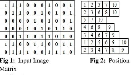
To illustrate the proposed method, a small binary image Fig 1 is taken. The column position of white pixel in
image is recorded in a matrix called position matrix is (Fig 2). The values of MinPos, Maxpos are 1 and 10
Get the first unmarked value (Fig 3a) from the Position Matrix. The unmarked value is 1(found in ROW 1, so CR=1) PV [] = {1}, FLAG= NOTPREVMARKED according to step 5.
Pass i: The adjacent values of 1 are 1 and 2. AVCR [] = {1, 2}. CR=1. The adjacent values of 1 are 1 according to step 7 i.e AVOR[]={1}.The AVCR[] values are corresponding marked cells in the Input Image (Fig 3c). As FLAG is NOTPREVMARKED , LABEL is
according to step 5. L=2 as LABEL=2.Pass i: The already Labeled, so change FLAG= PREVMARKED and L = Label assigned to the already Labeled cell corresponding marked cells in the Input Image (Fig 4d). As FLAG is PREVMARKED , LABEL will remain
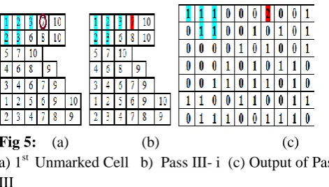
Get the first unmarked value (Fig 5a) from the Position Matrix. The unmarked value is 7(found in ROW 1 , so CR=1) PV [] = {1}, FLAG= NOTPREVMARKED NOTPREVMARKED , LABEL is incremented by one. (LABEL =3).
Fig 5: (a) (b) (c) a) 1st Unmarked Cell b) Pass III- i (c) Output of Pass III
PASS IV :
Get the first unmarked value (Fig 6a) from the Position Matrix. The unmarked value is 10(found in ROW 1 , so CR=1) PV [] = {10}, FLAG= NOTPREVMARKED according to step 5. L=3 as LABEL=3. Pass i: The adjacent values of 10 are 9, and 10. AVCR [] = {9, 10}. The adjacent value of 10 is 10 according to step 7 i.e AVOR[]={10}.The AVCR[] values are searched in CR and AVOR[] in CR+1 and those cells (10 in Row 1 and The cell marked in Row 3 is 10. The adjacent values of 10 are 9, and 10. AVCR [] = {9, 10}. The adjacent value of 10 is 10 according to step 7 i.e AVOR[]={10}. The AVCR[] values are searched in CR and AVOR[] in CR-1, CR+1 and marked. CR is incremented by 1 (CR =4). The cell marked in CR is NIL (PV [] = {}). There is no cell marked in Row 4 (PV[] = Ø).Fourth Pass is Over. Assign L to the corresponding marked cells in
the Input Image (Fig 5c). As FLAG is
Fig 6: (a) (b) (c) (d) (a) 1st Unmarked Cell (b) Pass IV- i (b) Pass IV- ii (d) Output of Pass IV
PASS V:
Get the first unmarked value (Fig 7a) from the Position Matrix. The unmarked value is 6(found in ROW 2 , so CR=2) PV [] = {7}, FLAG= NOTPREVMARKED according to step 5. L=4 as LABEL=4.Pass i: The adjacent values of 6 are 5, 6 and 7. AVCR [] = {5, 6, 7}. The adjacent value of 6 is 6 according to step 7 i.e AVOR[]={4}.The AVCR[] values are searched in CR and AVOR[] in CR+1 and those cells (6 in Row 2 and NIL in Row 3) are marked (Fig 7b). Now CR is incremented by 1 (CR =3). The cell marked in CR is NIL (PV [] = {NIL}). There is no cell marked in Row 3 (PV [] = Ø).Fifth Pass is Over. Assign L to the corresponding marked cells in the Input Image (Fig 7c). As FLAG is NOTPREVMARKED , LABEL is incremented by one. (LABEL =5).
Fig 7: (a) (b) (c) (a) 1st Unmarked Cell (b) Pass V- i c) Output of Pass V
PASS VI:
Get the first unmarked value (Fig 8a) from the Position Matrix. The unmarked value is 8(found in ROW 2, so CR=2) PV [] = {5}, FLAG= NOTPREVMARKED according to step 5. L=5 as LABEL=5.Pass i: The adjacent values of 8 are 7, 8 and 9. AVCR [] = {7, 8, 9}. The adjacent value of 8 is 8 according to step 7 i.e AVOR[]={8}.The AVCR[] values are searched in CR and AVOR[] in CR+1 and those cells (8 in Row 2 and NIL in Row 3) are marked (Fig 8b). Now CR is incremented by 1 (CR =3). The cell marked in CR is NIL (PV [] = {NIL}). There is no cell marked in Row 3
(AV [] = Ø).This Pass is Over. Assign L to the corresponding marked cells in the Input Image (Fig 8c). As FLAG is NOTPREVMARKED , LABEL is incremented by one. (LABEL =6).
Fig 8: (a) (b) (c) (a) 1st Unmarked Cell (b) Pass VI- i (c)
Output of Pass VI
PASS VII:
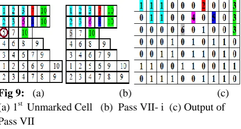
Get the first unmarked value (Fig 9a) from the Position Matrix. The unmarked value is 5(found in ROW 3, so CR=3) PV [] = {5}, FLAG= NOTPREVMARKED according to step 5. L=6 as LABEL=6.Pass i: The adjacent values of 5 are 4, 5 and 6. AVCR [] = {4, 5, 6}. The adjacent value of 5 is 5 according to step 7 i.e AVOR[]={5}.The AVCR[] values are searched in CR and AVOR[] in CR+1 and those cells (5 in Row 3 and NIL in Row 3) are marked (Fig 9b). Now CR is incremented by 1 (CR =4). The cell marked in CR is NIL (PV [] = {NIL}).
There is no cell marked in Row 4 (AV [] = Ø).This Pass is Over. Assign L to the corresponding marked cells in the Input Image (Fig 9c). As FLAG is NOTPREVMARKED , LABEL is incremented by one. (LABEL =7).
Fig 9: (a) (b) (c) (a) 1st Unmarked Cell (b) Pass VII- i (c) Output of Pass VII
PASS VIII:
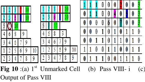
LABEL=7.Pass i: The adjacent values of 7 are 6, 7 and 8. AVCR [] = {4, 5, 6}. The adjacent value of 7 is 7 according to step 7 i.e AVOR[]={7}.The AVCR[] values are searched in CR and AVOR[] in CR+1 and those cells (7 in Row 3 and NIL in Row 4) are marked (Fig 10b). Now CR is incremented by 1 (CR =4). The cell marked in CR is NIL (PV [] = {NIL}). There is no cell marked in Row 4 (AV [] = Ø).Eigth Pass is Over.
Assign L to the corresponding marked cells in the Input Image (Fig 10c). As FLAG is NOTPREVMARKED , LABEL is incremented by one. (LABEL =8).
Fig 10 :(a) 1st Unmarked Cell (b) Pass VIII- i (c) Output of Pass VIII
PASS IX:
Get the first unmarked value (Fig 11a) from the Position Matrix. The unmarked value is 4(found in ROW 4 , so CR=4) PV [] = {4}, FLAG= NOTPREVMARKED according to step 5. L=8 as LABEL=8.Pass i: The adjacent values of 4 are 3, 4 and 5. AVCR [] = {3, 4, 5}. The adjacent value of 4 is 4 according to step 7 i.e AVOR[]={4}.The AVCR[] values are searched in CR and AVOR[] in CR+1, CR -1 and those cells (4 in Row 4 and 4 in Row 5) are marked (Fig 11b). Now CR is incremented by 1 (CR =5). The cell marked in CR is 4 (PV [] = {4}). Pass ii : The cell marked in Row 5 is 4. The adjacent values are 3, 4 and 5. AVCR [] = {3, 4, 5}. The adjacent value of 4 is 4 according to step 7 i.e AVOR[]={4}.The AVCR[] values are searched in CR and AVOR[] in CR-1, CR+1 and those cells (3 in Row 5) are marked (Fig 11c). Now CR is incremented by 1 (CR =6). The cell marked in CR is NIL (PV [] = {NIL}). There is no cell marked in Row 5 (PV[] = Ø).This Pass is Over. Assign L to the corresponding marked cells in the Input Image (Fig 11d). As FLAG is NOTPREVMARKED , LABEL is incremented by one. (LABEL =9)
Fig 11: (a) (b) (c) (d)
(a) 1st Unmarked Cell (b) Pass IX- i (b) Pass IX- ii (d) Output of Pass IX
PASS X
Fig 12: (a) (b) (c) (a) 1st Unmarked Cell (b) Pass X- i c) Pass X- ii
Fig 12 : (d) PASS X-iii (e) Output of Pass IX
PASS XI:
Get the first unmarked value (Fig 13a) from the Position Matrix. The unmarked value is 8(found in ROW 4 , so CR=4) PV [] = {8}, FLAG= NOTPREVMARKED according to step 5. L=10 as LABEL=10.Pass i: The adjacent values of 8 are 7, 8 and 9. AVCR [] = {7, 8, 9}. The adjacent value of 8 is 8 according to step 7 i.e AVOR[]={8}.The AVCR[] values are searched in CR and AVOR[] in CR+1, CR -1 and those cells (8 in Row 4 and 9 in Row 4) are marked (Fig 13b). Now CR is incremented by 1 (CR =5). The cell marked in CR is 6 (PV [] = {NIL}).
Fig 13 : (a) (b) (c) (a) 1st Unmarked Cell (b) Pass XI- i c) Output of Pass XI
There is no cell marked in Row 7 (PV[] = Ø).This Pass is Over. Assign L to the corresponding marked cells in the Input Image (Fig 13c). As FLAG is NOTPREVMARKED , LABEL is incremented by one. (LABEL =11).
PASS XII:
Get the first unmarked value (Fig 14a) from the Position Matrix. The unmarked value is 9(found in ROW 5 , so CR=5) PV [] = {9}, FLAG= NOTPREVMARKED according to step 5. L=11 as LABEL=11.Pass i: The adjacent values of 9 are 8, 9 and 10. AVCR [] = {8, 9, 10}. The adjacent value of 9 is 9 according to step 7 i.e AVOR[]={6}.The AVCR[] values are searched in CR and AVOR[] in CR+1, CR -1 and those cells (9 in Row 4 , 9 in Row 5, 9 in Row 6) are marked (Fig 14b). 9 in ROW 4 is already Labeled, so , change FLAG= PREVMARKED and L = Label assigned to the already Labeled cell (value 10). Now CR is incremented by 1 (CR =6). The cell marked in CR are 9 and 10 (PV [] = {9,10}). Pass ii : The cell marked in Row 6 is 9 and 10. The adjacent values are 8,9, and 10. AVCR [] = {8, 9, 10}. The adjacent value of 9, 10 are 9 and 10 according to step 7 i.e AVOR[]={9,10}.The AVCR[] values are searched in CR and AVOR[] in CR-1, CR+1 and those cells (10 in Row 6 and 9 in Row 7) are marked (Fig 14c). Now CR is incremented by 1 (CR =7). The cell marked in CR is 9 (PV [] = {9}). Pass iii : The cell marked in Row 7 is 9. The adjacent values are 8, 9 and 10. AVCR [] = {8, 9, 10}. The adjacent value of 9 is 9according to step 7 i.e AVOR[]={9}.
The AVCR[] values are searched in CR and AVOR[] in CR-1 ( last row) and those cells (8 in Row 7 are marked (Fig 14d). Now CR is incremented by 1 (CR =8). CR > LastRow. This Pass is Over. Assign L to the corresponding marked cells in the Input Image (Fig 14e). As FLAG is PREVMARKED , LABEL will remain same (LABEL =11).
Fig 14 : d) PASS XII-iii (e) Output of Pass XII
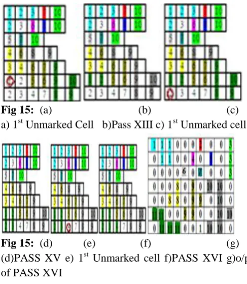
PASS XIII:
Get the first unmarked value (Fig 15a) from the Position Matrix. The unmarked value is 1(found in ROW 6, so CR=6) PV [] = {1}, FLAG= NOTPREVMARKED according to step 5. L=11 as LABEL=11.Pass i: The adjacent values of 1 are 1 and 2. AVCR [] = {1, 2}. The adjacent value of 1 is 1 according to step 7 i.e AVOR[]={1}.The AVCR[] values are searched in CR and AVOR[] in CR+1, CR -1 and those cells (-1 in Row 6 , 2 in Row 6) are marked (Fig 15b). Now CR is incremented by 1 (CR =7). The cell marked in CR is NIL and 10 (PV [] = {NIL}). There is no cell marked in Row 7 (PV[] = Ø).This Pass is Over. Assign L to the corresponding marked cells in the Input Image As FLAG is NOTPREVMARKED , LABEL is incremented by one. (LABEL =12).
PASS XIV:
Get the first unmarked value (Fig 15c) from the Position Matrix. The unmarked value is 2(found in ROW 7, so CR=7) PV [] = {1}, FLAG= NOTPREVMARKED according to step 5. L=12 as LABEL=12.Pass i: The adjacent values of 1 are 1, 2. AVCR [] = {1, 2}. The adjacent value of 1 is 1 according to step 7 i.e AVOR[]={1}.The AVCR[] values are searched in CR and AVOR[] in CR -1 and those cells (1,2 in Row) are marked (Fig 15d). 2 in ROW 6 is already Labeled , so , change FLAG= PREVMARKED and L = Label assigned to the already Labeled cell (value 11). Now CR is incremented by 1 (CR =8). CR > LastRow. This Pass is over. Assign L to the corresponding marked cells in the Input Image .As FLAG is PREVMARKED, LABEL will remain same (LABEL =12).
PASS XV:
Get the first unmarked value (Fig 15e) from the Position Matrix. The unmarked value is 4 (found in ROW 7, so CR=7) PV [] = {4}, FLAG= NOTPREVMARKED according to step 5. L=12 as LABEL=12.Pass i: The adjacent values of 4 are 3, 4 and 5. AVCR [] = {3, 4, 5}. The adjacent value of 4 is 4 according to step 7 i.e AVOR[]={4}.The AVCR[] values are searched in CR and AVOR[] in CR -1 and those cells (3 in Row 7 and 4 in Row 7) are marked (Fig 15f). 3 in ROW 7 is already Labeled , so , change FLAG= PREVMARKED and L = Label assigned to the already Labeled cell (value 11). Now CR is incremented by 1 (CR =8). CR > LastRow. This Pass is Over. Assign L to the corresponding marked cells in the Input Image (Fig 15g). As FLAG is PREVMARKED , LABEL will remain same (LABEL =12).
Fig 15: (a) (b) (c) a) 1st Unmarked Cell b)Pass XIII c) 1st Unmarked cell
Fig 15: (d) (e) (f) (g) (d)PASS XV e) 1st Unmarked cell f)PASS XVI g)o/p of PASS XVI
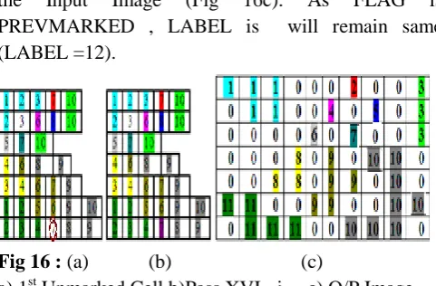
PASS XVI:
those cells (7 in Row 7 and 7 in Row 7) are marked There are 11components found and those components are labeled as 1 to 11.
III. EXPERIMENTAL RESULTS
The experimentation of the algorithm is implemented in Matlab Tool and was carried out on the ICDAR data set consisting of 250 different images. The images are converted in to binary image by applying otsu’s threshold method [8]. Some of the images taken for the experiment are shown in Fig 17. The experimental results of Fig 18 is shown in Table I .The experimental results in this research confirm that the new proposed method labels the connected component and gives the number of components present in the binary images
EVALUATED NUMBER OF CONNECTED COMPONENT
Image Size No. of Connected
This paper projected a new 4 way positional connected component labeling algorithm to label the connected components and to report the number of components present in binary image. The proposed technique is an important stage for the object extraction method. Experiments are conducted by applying proper thresholding technique on various images taken from ICDAR datasets and found that the outcome of the algorithm is 100%.
V.
REFERENCES
[1] Fu Chang and Chun-Jen Chen, “A Component-Labeling Algorithm Using Contour Tracing Technique” , Document Analysis and Recognition, Proceedings, pp 741 – 745,2003.
[2] Yuhai Li, Kuizhi Mei, Peixiang Dong ,” An
Efficient and Low Memory Requirement
Algorithm for Extracting Image Component Information”, International Journal of Advanced Intelligence,Volume 3, Number 2, pp.255-267,2011.
[3] Phaisarn Sutheebanjard and Wichian
Premchaiswadi (2011) ,” Efficient scan mask techniques for connected components labeling algorithm”, EURASIP Journal on Image and Video Processing, 2011:14
Homogeneous Multicore Architectures”, Journal of Physics: Conference Series 256,2010
[5] A. Rakhmadi, M. S. M. Rahim, A. Bade, H. Haron, I. M. Amin,,”Loop Back Connected Component Labeling Algorithm and Its Implementation in Detecting Face”, World Academy of Science, Engineering and Technology 40 , 2010
[6] Tetsuo Asano , Hiroshi Tanaka,“In-place Algorithm for Connected Components Labeling”, Journal of Pattern Recognition Research 10-22, 2010.
[7] G.Gayathri Devi, Dr.C.P.Sumathi, 2014,”Positional Connected Component Labeling Algorithm “, Indian Journal of Science and Technology, Volume 7, Issue 3, pages 306-311, 2014.