Programmable Logic Controller based
Continuous Non Linear Spherical tank Level
Control Process
Sudhahar S1,Rajesh T2, Dr. Sharmila D3
Assistant Professor, Department of EIE, Bannari Amman Institute of Technology, Sathyamangalam, India1 Assistant Professor, Department of EIE, Bannari Amman Institute of Technology, Sathyamangalam, India 2
Professor, Department of EIE, Bannari Amman Institute of Technology, Sathyamangalam, India3
ABSTRACT:The level control of non-linear tanks (conical, spherical, etc) is the immense challenge in process control and it cannot be effectively controlled by means of conventional linear P+I+D controller. Hence an attempt is made in this paper as auto tuning PID controller design for spherical tank level control. For each stable operating point, a first order process model was identified using process reaction curve method. The real time implementation is done in Allen Bradley PLC The experimental results shows that proposed control scheme have good set point tracking, disturbance rejection capability, nominal time domain specifications and lower integral square error.
KEYWORDS: Spherical, PID, PLC ISE, PRC.
I.INTRODUCTION
In most of the process industries controlling of level, flow, temperature and pressure is a challenging one. Based on the plant dynamics, they may be classified as linear and non-linear processes. In level control process, the tank systems like cylindrical, cubical are a linear one, but that type of tanks does not provides a complete drainage. For complete drainage of fluids, a spherical bottomed cylindrical tank is used in some of the process industries, where its nonlinearity might be at the bottom only. The drainage efficiency can be improved further if the tank is fully spherical. But continuous variation in the tank system makes it highly non-linear and hence the liquid level control in such systems is difficult. A spherical shaped tank system are mainly used in Colloidal mills, Leaching extractions in pharmaceutical and chemical industries, food processing industries, Petroleum industries, Molasses, Liquid feed and Liquid fertilizer storage, Chemical holding & mix tank, Biodiesel processing and reactor tank. To avoid settlement and sludge in Storage and holding tanks, the spherical tanks are used.
II. PROPOSED WORK
The level process station was used to conduct the experiments and collect the data. The computer acts as a controller. It consists of the software used to control the level process station. The setup consists of a process tank, reservoir tank, control valve, I to P converter, level sensor and pneumatic signals from the compressor. When the set up is switched on, level sensor senses the actual level values initially then signal is converted to current signal in the range 4 to 20mA.This signal is then given computer through data acquisition cord. Based on the values entered in the controller Settings and the set point the computer will take control action the signal sent by the computer is taken to the station again through the cord. This signal is then converted to pressure signal using I to P converter. Then the pressure signal acts on a control value which controls the flow of water in to the tank there by controlling the level. The tank is made up of stainless steel body and is mounted over a stand vertically. Water enters the tank from the top and leaves the bottom to the storage tank.
A.MATHEMATICAL MODELING OF PROCESS
Types of Non-linear Approximations: a. Taylor Series Approximation b. Optimal Approximation c. Global Approximation d. Jacobian Method One of these methods, Taylor’s series method is simple and accurate over certain range near the steady state point.
Figure. 1 Process Modelling to obtain transfer function
B.PLC PROGRAMMING
Open contact:
When the supply is given to open contact (Base of the NPN transistor) open contact will be closed (NPN transistor will
operate in saturation mode current will flow from collector to emitter) The supply is removed the contact will open
again (NPN transistor will operate in cut-off mode current will not flow from collector to emitter)
Closed contact:
When the supply is given to closed contact (Base of the PNP transistor) closed contact will be opened (PNP transistor will operate in cut-off mode). The supply is removed the contact will close again (PNP transistor will operate in saturation mode)
Output or Relay coil:
If supply is available to the output coil (at pin ), then the coil will be energized and maintains ON state, else this coil
will de-energized and maintains OFF state. It usually assigned to the output module, O:0/0 (Output: 0th Module/ 0th
output(0 to 9)) Can be assigned to a memory, B:1/0 (Binary: 1st word (0 to 255)/ 0th bit (0 to 15))
Open and closed contact assignments:
can be assigned to input module, I:0/0 (Input: 0th Module/ 0th input(0 to 13))
Can be assigned to a memory, B:0/0 (Binary: 0th word (0 to 255)/ 0th bit (0 to 15))
We can even assign a output of previous or next rung to open or closed contact
On delay timer:
III. DESIGN OF LADDER LOGIC FOR CONTROLLING CONTINUOUS LEVEL CONTROL PROCESS
A. PID Controller (Proportional/Integral/derivative):
point. The PID equation controls the process by sending an output signal to the actuator. The greater the error between the set point and the process variable input, the greater the output signal, and vice versa. An additional value (feed forward or bias) can be added to the control output as an offset. The result of the PID calculation (control variable) will drive the process variable you are controlling toward the set point. The PID instruction can be operated in the timed mode or the STI mode. In the timed mode, the instruction updates its output periodically at a user-selectable rate. In the STI mode, the instruction should be placed in an STI interrupt subroutine. It then updates its output every time the STI subroutine is scanned. The STI time interval and the PID loop update rate must be the same in order for the equation to
execute properly. Clicking Setup Screen on the PID instruction displays a dialog that allows you to enter additional
parameters. These parameters are described here. Set point Max=16383, Output Max=100
IV. EXPERIMENTAL RESULTS AND DISCUSSIONS
Figure 1 and 2 shows the real time experimental setup and process reaction curve method to obtain model of the process for non linear continuous level control process.
Figure. 1 Real time experimental setup
Figure. 2 Process Reaction Cure method for Spherical tank level control process
Figure 3 shows that real time controller effect on non linear spherical tank level control process for various tuning methodology implemented in PLC. An experimental result shows that digital controller having good set point tracking capability.
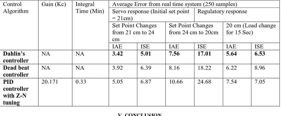
Table I. Comparison of Performance Indices – Middle Range of Set Point
Control Algorithm
Gain (Kc) Integral
Time (Min)
Average Error from real time system (250 samples) Servo response (Initial set point
= 21cm)
Regulatory response
Set Point Changes from 21 cm to 24 cm
Set Point Changes from 24 cm to 20cm
20 cm (Load change for 15 Sec)
IAE ISE IAE ISE IAE ISE
Dahlin’s controller
NA NA 3.42 5.01 7.56 17.01 5.64 6.53
Dead beat controller
NA NA 3.92 6.39 8.16 18.22 6.22 8.96
PID controller with Z-N tuning
20.171 0.33 5.05 6.87 10.66 24.68 7.54 7.05
V. CONCLUSION
In this proposed work, the response of a nonlinear system model was implemented using PLC and the required test was done to get the respective transfer function. The transfer function was obtained from the process reaction curve method. The various tuning method is used to obtain the tuning parameters for obtaining smooth response without transient outputs. The implementation of various algorithms for plant transfer function allows an effective way of functioning. It has more robust stability and efficiency and can solve the tuning problems of PID controller parameters more easily and quickly than the existing methods. The experimental result proves that digital controller having lesser error criteria and optimum time domain specifications.
REFERENCES
[1] Arturo Y. Jaen-Cuellar, Rene de J. Romero-Troncoso, Luis Morales-Velazquez,and Roque A. Osornio-Rios,2013, “PID-Controller Tuning Optimization withGenetic Algorithms in Servo Systems,” International Journal of Advanced Robotic Systems, 10, pp.1-14.
[2] Astrom, K.J., and Hagglund, T., 2004, “Revisiting the Ziegler-Nichols step response method for PID control,” Journal of Process Control, 14, pp. 635-650.
[3] Anandanatarajan, R., Chidambaram, M., and Jayasingh, T., 2006, “Limitations of a PI controller for a first-order nonlinear process with dead time,” ISA Transactions, 45(2), pp. 185-199.
[4] Cohen, G. H., and Coon G. A., 1953, “Theoretical Consideration of Retarded Control,” Trans. ASME, 75,pp. 827-834. [5] Ziegler, J.G., and Nichols, N.B., 1942, “Optimum Settings for Automatic Controller,” Transaction of ASME,64, pp. 759-768.
[6] Anandanatarajan, R., and Mourougapragash, S., 2008, “Experimental Evaluation of a Controller Using a Variable Transformation Smith Predictor for a Nonlinear Process with Dead Time,” ISA Transactions, 47(2), pp. 217-221.
[7] Bhuvaneswari, N. S., Uma, G., and Rangaswamy, T. R., 2008, “Neuro based model reference adaptive control of a conical tank level process,” Journal of Control and Intelligent Systems, 36(1), pp. 98-106.
[8] Ganesh Ram, A., and Abraham Lincoln, S., 2013, “A Model Reference-Based Fuzzy Adaptive PI Controller for Non-Linear Level Process System,” IJRRAS, 14 (2), pp. 477-486.
[9] W. Jie-sheng, Z. Yong and W. Wei, “Optimal Design of PI/PD Controller for Non-Minimum Phase System,” Transactions of the Institute of Measurement and Control, vol. 28, no. 1, 2006.
[10] S. Mohd Saad, hishamuddin jamaluddin and Z. Intan, M. Darus, “PID Controller Tuning Using Evolutionary Algorithms,” Wseas Transactions on Systems And Control, vol. 7, no. 4, 2012, pp. 139-149.
[11] J. Zhang, J. Zhuang, H. Du and S. Wang, “Self‐ Organizing Genetic Algorithm Based Tuning of PID Controllers,” Information Sciences, vol. 179, no. 7, 2009, pp. 1007 – 1018.