ISSN (Print) : 2320 – 3765 ISSN (Online): 2278 – 8875
I
nternational
J
ournal of
A
dvanced
R
esearch in
E
lectrical,
E
lectronics and
I
nstrumentation
E
ngineering
(An ISO 3297: 2007 Certified Organization)
Vol. 5, Issue 12, December 2016
Robust Design of Hybrid Railway Power
Conditioner for Efficient and Fast Railway
System
Attuluri Venkata Lakshmi
1
, M.Venkateswarlu
2
M.Tech Student, Dept. of EEE, Dr. Samuel George Institute of Engineering &Technology, Markapur, JNTU Kakinada
University, India1
Associate Professor, Dept. of EEE, Dr. Samuel George Institute of Engineering &Technology, Markapur, JNTU
Kakinada University, India2
ABSTRACT: Co-phase traction power system has high potential to be power supply for high-speed railway. However, the dc operation voltage of conventional power quality compensation device within, such as railway power quality conditioner, is high and may limit its application and development. The hybrid power quality conditioner (HPQC), in which a capacitive coupled LC structure is added, is thus proposed for lower operation voltage. However, there is less investigation and study on the HPQC parameter design for minimum operation voltage when harmonic compensation is concerned. In this paper, the HPQC design for minimum dc operation voltage under comprehensive fundamental and harmonic compensation is being proposed and introduced. Analysis and case study are also performed to show the advantage of the proposed HPQC design. Simulation and laboratory-scaled experimental results are presented to show effective reduction in dc operation voltage using the proposed HPQC design. Through the simulation and experimental case study and verification, there is a reduction of 15% in operation voltage using the proposed hybrid LC structure design compared with the conventional design. The proposed design does not add much additional cost and can also reduce the coupling inductance value. Similar analysis procedure may be also applied to other LC hybrid-structured active power compensators.
KEYWORDS: Co-phase traction, high-speed locomotive,hybrid filter, power quality compensation.
I. INTRODUCTION
SINGLE-PHASE ac power supply has been widely adopted in long-distance electrified railway in many countries. Electrical locomotives introduce reactive power and harmonic problems into the traction power supply systems. As the amount of rail traffic increases, the issue of power quality distortion is becoming more critical Moreover, electrical isolations such as neutral sections between power regions are required, which causes reduction in locomotive speed As a result, a traction power supply suitable for high-speed railway is required to overcome the aforementioned issues.
II. EXISTING SYSTEM
ISSN (Print) : 2320 – 3765 ISSN (Online): 2278 – 8875
I
nternational
J
ournal of
A
dvanced
R
esearch in
E
lectrical,
E
lectronics and
I
nstrumentation
E
ngineering
(An ISO 3297: 2007 Certified Organization)
Vol. 5, Issue 12, December 2016
III. PROPOSED SYSTEM
In this paper, the comprehensive HPQC design for minimum operation voltage under both fundamental and harmonic compensation is discussed. The control principle of comprehensive power quality compensation of system unbalance, reactive power, and harmonics in co-phase traction power supply is introduced. In order to show the advantages of HPQC over RPC, the motivation and differences of the proposed HPQC structure from the conventional RPC one is reviewed.
At around 2012, in a hybrid device combining active and passive compensators, which is named as the hybrid power quality compensator (HPQC), was proposed for compensation in co-phase traction power supply. This approach is advantageous not only for reduction in system capacity and initial cost but also the reduction of converter switching operation loss compared with conventional co-phase traction power supply system. Hereafter, minimum dc operation voltage design of this HPQC under fundamental compensation of system unbalance and reactive power was discussed. However, there is no detailed description of HPQC design under comprehensive compensation including considerations of both fundamental and harmonic compensation. Moreover, it has been mostly suggested that the resonant frequency of the passive LC branch of a hybrid-structured compensator can be tuned tothe frequency where system harmonics are mostly concentrated at to minimize the dc operation voltage of the compensator. However, the idea still lacks theoretical support or mathematical derivation. The required output compensation power from a co-phase traction power quality compensator is shown in the following.
COMPARISONS BETWEEN COPHASE TRACTION WITH CONVENTIONAL AND PRAPOSED HPQC
ISSN (Print) : 2320 – 3765 ISSN (Online): 2278 – 8875
I
nternational
J
ournal of
A
dvanced
R
esearch in
E
lectrical,
E
lectronics and
I
nstrumentation
E
ngineering
(An ISO 3297: 2007 Certified Organization)
Vol. 5, Issue 12, December 2016
Based on the instantaneous pq theory and the compensator control system block diagram is presented in in Figure 3. The instantaneous load active and reactive power is first computed and is used to determine the required compensation power and thus the required compensation current. They are used to generate pulse width modulation (PWM) signals, which are used to control the electronic switches insulated-gate bipolar transistors within the compensator to output the required compensation current. The discussions that follow are developed based on the theory above. Differences of configuration and operation of the conventional RPC and the proposed HPQC are discussed.
I. Converter Topology
With reference to Figures 1 and 2 it can be observed that both the conventional RPC and the proposed HPQC are a back-to-back converter with a common dc link. The major difference between them is the Vac phase coupled structure. In the conventional RPC, it is an inductive coupled structure, and in the proposed HPQC, it is a hybrid inductor– capacitor (LC) capacitive coupled structure. The passive structure in HPQC can help to reduce the operation voltage during compensation. This will be covered in the next subsection
II. Operation Voltage
In addition to converter topology, another difference is that the operation voltage of the proposed HPQC is lower than that of the conventional RPC. The vector diagram showing their operation voltage is presented in Figure 4. The mathematical relationship is shown in the following:
ISSN (Print) : 2320 – 3765 ISSN (Online): 2278 – 8875
I
nternational
J
ournal of
A
dvanced
R
esearch in
E
lectrical,
E
lectronics and
I
nstrumentation
E
ngineering
(An ISO 3297: 2007 Certified Organization)
Vol. 5, Issue 12, December 2016
COMPREHENSIVE HPQC COMPENSATOR PARAMETER DESIGN BASED ON MINIMUM OPERATION VOLTAGE
The usage of HPQC operation voltage may be divided ac-cording to two purposes: fundamental (VinvaLC1) and harmonic (VinvaLCh) compensation. In traction load fundamental compensation occupies most of the compensation capacity. Here, the comprehensive HPQC design will be presented based on the criteria of minimizing the operation voltage for providing these two compensation modes. Thus
I. HPQC Design of minimum operation voltage for fundamental compensation
Fundamental compensation in co-phase traction power supply includes basic compensation for system unbalance and reactive power. In short, the operation voltage for fundamental com- compensation is the required operation voltage to provide power quality compensation (of system unbalance and reactive power) without harmonic compensation. It dominates the major portion of power quality compensation, as harmonics are usually less significant compared with reactive power and system unbalance in a power system.
The design of HPQC Vac coupled impedance has been discussed in the previous section. The optimum parameter selection of Vac phase coupled impedance XLCa may be also determined by taking derivative of with XLCa and setting it has zero. The process and result are consistent with the expression Notice that the negative sign in the expression refer to a capacitive coupled impedance. Thus
II. HPQC Design of minimum operation voltage for Harmonic compensation
Although fundamental system unbalance and reactive power compensation occupy the major portion of power quality compensation capacity, harmonic compensation cannot be neglected as it will also add to the overall compensator operation voltage requirement. With reference to it can be observed that the discussion relates also to the harmonic impedance that an optimum selection of coupled inductance La and Ca must be chosen to minimize the
ISSN (Print) : 2320 – 3765 ISSN (Online): 2278 – 8875
I
nternational
J
ournal of
A
dvanced
R
esearch in
E
lectrical,
E
lectronics and
I
nstrumentation
E
ngineering
(An ISO 3297: 2007 Certified Organization)
Vol. 5, Issue 12, December 2016
The expression for the impedance of coupled inductance and coupled capacitance
The relationship between the values of kL and kC can be expressed in the following:
The impedance at the hth harmonics can be expressed as
The load harmonic current can be expressed as
ISSN (Print) : 2320 – 3765 ISSN (Online): 2278 – 8875
I
nternational
J
ournal of
A
dvanced
R
esearch in
E
lectrical,
E
lectronics and
I
nstrumentation
E
ngineering
(An ISO 3297: 2007 Certified Organization)
Vol. 5, Issue 12, December 2016
The Vbc phase coupled impedance may be designed according to the minimum operation voltage VinvaLC, as expressed in
IV. HPQC OPERATION VOLTAGE WITH THE PROPOSED DESIGN
Assuming that the HPQC parameter is designed according to previous discussion for minimum operation voltage. As for the HPQC dc link operation voltage, it may be calculated as square root 2 times of the HPQC operation voltage.
IV. Comprehensive HPQC Design Procedure The Vac phase coupled impedance La is
Vac phase coupled inductance
ISSN (Print) : 2320 – 3765 ISSN (Online): 2278 – 8875
I
nternational
J
ournal of
A
dvanced
R
esearch in
E
lectrical,
E
lectronics and
I
nstrumentation
E
ngineering
(An ISO 3297: 2007 Certified Organization)
Vol. 5, Issue 12, December 2016
The dc link operation voltage in HPQC
V. CASE STUDY AND SIMULATION
Simulation Circuit
ISSN (Print) : 2320 – 3765 ISSN (Online): 2278 – 8875
I
nternational
J
ournal of
A
dvanced
R
esearch in
E
lectrical,
E
lectronics and
I
nstrumentation
E
ngineering
(An ISO 3297: 2007 Certified Organization)
Vol. 5, Issue 12, December 2016
power factor usually ranges from 0.8 to 0.9, with an average of 0.85. The analysis that follows is performed based on these assumptions. As introduced, the operation voltage for HPQC using the proposed parameter design may be determined. In order to eliminate the effect of PCC voltage in the analysis, the operation voltage is expressed in per unit, with base of Vac, as expressed in shown at the bottom of the page. Itcan be observed from the expression that the
HPQC operation voltage is dependent on load power factor, harmonics, and HPQC coupled impedance (both inductance and capacitance).By substituting the data in Table I into the value of kL in the proposed design can be
determined as 0.023. Thecorresponding HPQC operation voltage rating is calculated using and the value is 0.4833. This value is close to the minimum HPQC operation for fundamental compensation, i.e., 0.48. The value corresponds to HPQC dc link voltage of around 18.7 kV for a 27.5-kV PCC voltage. Notice that, conventionally, the coupled inductance and capacitance parameter in a hybrid-structured compensator is tuned at the frequency where system harmonics are mostly concentrated. In the WuQing substation, this corresponds to the third harmonics, whose kL value
ISSN (Print) : 2320 – 3765 ISSN (Online): 2278 – 8875
I
nternational
J
ournal of
A
dvanced
R
esearch in
E
lectrical,
E
lectronics and
I
nstrumentation
E
ngineering
(An ISO 3297: 2007 Certified Organization)
Vol. 5, Issue 12, December 2016
In order to provide comprehensive power quality compensation of system unbalance, reactive power, and harmonics, HPQC is connected across the two substation single-phase outputs and is switched in. Two conditions are being simulated, namely, HPQC Vac phase coupled LC values tuned at third harmonic frequency and HPQC Vac phase coupled LC values using the proposed design. The parameter settingis chosen according to the theory developed and is shown in Table II. Notice that the overall Vac phase fundamental coupled impedance is exactly the same, which offers the minimum HPQC operation voltage during fundamental compensation, in the two conditions. The only difference is the value of LC parameters. Details of the simulation results and analysis are shown in the following.
A. HPQC Vac Phase Coupled LC Values Tuned at Third Harmonic Frequency (VDC = 18.7 kV)
First of all, the parameter design for hybrid filter, being used in most research studies, is simulated. It has been suggested
ISSN (Print) : 2320 – 3765 ISSN (Online): 2278 – 8875
I
nternational
J
ournal of
A
dvanced
R
esearch in
E
lectrical,
E
lectronics and
I
nstrumentation
E
ngineering
(An ISO 3297: 2007 Certified Organization)
Vol. 5, Issue 12, December 2016
according to the data in Table I, the load harmonics are mostly concentrated at the third harmonics. Therefore, in this simulation subsection, the HPQC Vac phase coupled LC values are tuned to the third harmonics, and the parameters are shown in Table II.
The dc link voltage used is 18.7 kV, which can be concluded from (21), to show the pros of the proposed HPQC design. The simulated three-phase source voltage and current wave-forms are shown in Figure 8. It can be observed that the system source current unbalance and harmonics are not completely eliminated. The system source current harmonic distortion is 21%, whereas its unbalance is 8%. The harmonic compensation performance is thus not satisfactory.
B. HPQC Vac Phase Coupled LC Values Using the Proposed Design (VDC = 18.7 kV)
Next, the system performance of HPQC with the proposed parameter design under harmonic compensation is investigated. According to (21), the HPQC operation voltage rating is around 0.4833 using the proposed parameter design under the specified condition. This corresponds to a dc link voltage of around 18.7 kV for a 27.5-kV PCC voltage. The simulated three-phase source voltage and current wave-forms are shown in Figure 9. It can be observed that the three-phase source current harmonics and unbalance are eliminated. Furthermore, the reactive power is also compensated. This can be verified by its harmonic distortions of 2.2%, unbalance of 4%, and power factor of 0.99. A summarized system performance obtained from the simulations mentioned is shown in Table III. The dc link voltage used is 18.7 kV during compensation. It can observed from the data that, with the proposed HPQC parameter design, the HPQC operation voltage can be lowered and can also provide satisfactory compensation performance. With the same dc link voltage, the compensation performance is not satisfactory using parameter design normally used previously. It is also found that, using the conventional design, the compensation performance is satisfactory only when the dc link operation voltage reaches 22 kV. There is, therefore, a 15% further reduction in operation voltage using the proposed HPQC design.
C. HPQC Vac Phase Coupled LC Values Using the Proposed Design under Different Load Power Factor Conditions (VDC = 18.7 kV)
In order to evaluate the power quality compensation ability of HPQC with the proposed design, simulations are done again under different load power factor conditions. Notice that critical conditions of totally load active or reactive power are also included to have comprehensive investigations. The results are shown in Table IV. It can be observed from the results that the designed HPQC can provide satisfactory power quality compensation for wide range of reactive power, except for conditions near loadings with totally reactive power or active power. This can be explained by parameter design exceeding designed range for heavy reactive power loading and insufficient dc link operation voltage for active power transfer under load with total active power. Since traction load power factor ranges from 0.8 to 0.85, the proposed parameter design for HPQC can provide satisfactory compensation for most loading conditions.
ISSN (Print) : 2320 – 3765 ISSN (Online): 2278 – 8875
I
nternational
J
ournal of
A
dvanced
R
esearch in
E
lectrical,
E
lectronics and
I
nstrumentation
E
ngineering
(An ISO 3297: 2007 Certified Organization)
Vol. 5, Issue 12, December 2016
D. HPQC Vac Phase Coupled LC Values Using the Proposed Design under Varying Load (VDC = 18.7 kV)
In order to further evaluate the system performance using the proposed design, simulations are done with a varying load. Suppose that the load capacity is increased from 0.6 to full rated load value near 0.5 s, the simulated primary source current and voltage waveforms are shown in Figure 10.
It can be observed that the system performance is within standard using the proposed parameter design when loading condition is varied.
EXPERIMENTAL VERIFICATIONS
In order to verify the system performances of the proposed co-phase traction power supply system with HPQC of minimum operation voltage and its corresponding design under comprehensive compensation, including harmonic consideration, a low-capacity laboratory-scaled hardware prototype is constructed. It can be observed from (23) that the HPQC operation voltage is proportional to the PCC voltage Vac and is independent of fundamental loading capacity.
Therefore, the validity of the proposed HPQC in reducing operation voltage can be verified using this low-capacity hardware prototype. The circuit schematic and hardware appearance of the prototype are shown in Figure 11.The V/V transformer is composed of two 5-kVA single-phase transformers. The traction load is represented using a rectifier
R−L circuit, with a linear capacity of 150 VA. The load resistance and inductance are around 10 Ω and 30 mH, respectively. The control of the compensation is accomplished using DSP2812 according to the control block diagram shown in Figure 3. The PWM signal generation is achieved using hysteresis PWM tracking techniques.
Figure 11. Circuit schematic of the hardware prototype for verification of performances in the proposed co-phase traction power supply system with HPQC.
The operation voltage of Vac is 50 V. The presence of harmonics is caused by the nonlinear diode in the load rectifier
and adds to the requirement of the HPQC operation voltage. According to the calculation in (6), the minimum dc link operation voltage for fundamental compensation is around 40 V. On the other hand, the dc link operation voltage is around 41 V using the proposed parameter design. In the experiment with compensation, two conditions are being verified. Similar to the simulation, the two conditions are HPQC with parameters LC tuned at 3rd harmonics (A) and Proposed Design (B). The detailed parameters are shown in Table V. The system waveforms are captured using a Yokogawa DL750 16-channel Scope order oscilloscope, and power quality is monitored using a Fluke43B single-phase power quality analyzer. Captured waveforms and screens are presented.
ISSN (Print) : 2320 – 3765 ISSN (Online): 2278 – 8875
I
nternational
J
ournal of
A
dvanced
R
esearch in
E
lectrical,
E
lectronics and
I
nstrumentation
E
ngineering
(An ISO 3297: 2007 Certified Organization)
Vol. 5, Issue 12, December 2016
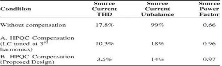
First, the system performance of co-phase traction power without compensation is investigated. The system waveforms obtained are shown in Figure 12. Absence of waveforms at Figure 12(f)–(h) indicates absence of power quality conditioner. Waveform with larger amplitude refers to the voltage, whereas that with a smaller one refers to the current. It can be clearly observed that the system suffers from unbalance and harmonic problem. The system unbalance is around 99%, with current harmonic distortions of 17.8%.
B. Co-phase Traction Power with HPQC Using the Conventional Design (VDC = 41 V)
Next experimental results are done with co-phase traction power supply with HPQC compensation using the conventional parameter design. In other words the Vac phase coupled inductance La and capacitance Ca is selected such
that its resonant frequency is located at the third harmonics, where load harmonics are mostly concentrated (refer to Table I for reference). The HPQC circuit parameters are shown in Table III. In order to compare the performance with HPQC of the pro-posed design the same dc link voltage of 41 V is being chosen. The system waveforms obtained through experimental results are shown in Figure 13. It can be observed that, with the same dc link voltage, the three-phase source current waveforms suffer from obvious harmonic distortion, particularly at three-phase C current. This indicates that the compensation performance is not satisfactory when using HPQC of the conventional coupled impedance design. The system source current still suffers from significant harmonic problem.
Figure 12. Detailed experimental system waveforms captured for co-phase traction power supply without compensation. (a) System source voltage and current of phase A. (b) System source voltage and current of phase B. (c) System source voltage and current of phase C. (d) Vac phase voltage and current at the secondary side. (e) Vbc phase voltage and current at the secondary side. (f) Vac phase compensation.
ISSN (Print) : 2320 – 3765 ISSN (Online): 2278 – 8875
I
nternational
J
ournal of
A
dvanced
R
esearch in
E
lectrical,
E
lectronics and
I
nstrumentation
E
ngineering
(An ISO 3297: 2007 Certified Organization)
Vol. 5, Issue 12, December 2016
Fig. 14. Detailed experimental system waveforms captured for co-phase traction power supply with the proposed HPQC design. (a) System source voltage and current of phase A. (b) System source voltage and current of phase B. (c) System source voltage and current of phase C. (d) Vac phase voltage and current at the secondary side. (e) Vbc phase voltage and current at the secondary side. (f) Vac phase compensation current. (g) Vbc phase compensation current. (h) DC link voltage.
C. Co-phase Traction Power with Compensation with HPQC Using the Proposed Design (VDC = 41 V)
Next, experiments are conducted on the laboratory-scaled co-phase traction power with HPQC using the proposed HPQC parameter design in this paper. The dc link voltage is also set as 41 V, according to the discussions and calculations. The HPQC circuit parameters can be found in Table III. The system waveforms obtained with RPC under such conditions are presented in Figure 14. It can be observed that, compared with those in Figure 13 the three-phase source current becomes balanced and harmonics are eliminated. The total harmonic distortion is reduced to within 3%, while the system unbalance is also reduced.
For comparisons, summarized data of system statistics with-out compensation and with HPQC compensation using the proposed and conventional parameter designs (Vdc = 41 V) are shown in Table VI. Recorded waveforms and power
ISSN (Print) : 2320 – 3765 ISSN (Online): 2278 – 8875
I
nternational
J
ournal of
A
dvanced
R
esearch in
E
lectrical,
E
lectronics and
I
nstrumentation
E
ngineering
(An ISO 3297: 2007 Certified Organization)
Vol. 5, Issue 12, December 2016
Fig. 15. Recorded experimental waveforms and power quality data from primary grid phase A. (a) before compensation. (b) With HPQC compensation (LC tuned at third harmonics). (c) With HPQC compensation (proposed design).
Fig. 16. Recorded experimental waveforms and power quality data from primary grid phase B. (a) before compensation. (b) With HPQC compensation (LC tuned at third harmonics). (c) With HPQC compensation (proposed design).
D. Co-phase Traction Power with Compensation with HPQC under Load Variations
ISSN (Print) : 2320 – 3765 ISSN (Online): 2278 – 8875
I
nternational
J
ournal of
A
dvanced
R
esearch in
E
lectrical,
E
lectronics and
I
nstrumentation
E
ngineering
(An ISO 3297: 2007 Certified Organization)
Vol. 5, Issue 12, December 2016
proposed design when load varies. The price of conventional STATCOM or RPC ranges from US $38–$50/kVA [26]; reduction of device capacity in HPQC thus also indicates cost reduction. Furthermore, the passive capacitor bank or SVC is relatively less expensive. According to the reference, the price of SVC is only around $18/kVA. With nearly 45% reduction in HPQC operation voltage and thus device capacity, the price reduction is significant.
Fig. 18. Experimental system waveforms for co-phase traction power supply with HPQC of the proposed parameter design under load variations, system voltage and current waveforms in (a) phase A, (b) phase B, (c) phase C, and (d) load current
VI. CONCLUSION
In this paper, the LC parameter design in HPQC has been investigated for reduction of the operation voltage under fundamental and harmonic compensation. HPQC is previously pro-posed for reduction in operation voltage when providing power quality compensation in co-phase traction power. It works by introducing a capacitive LC branch as the coupled impedance. However, the design is mostly focused on fundamental compensation. Normally, the LC
ISSN (Print) : 2320 – 3765 ISSN (Online): 2278 – 8875
I
nternational
J
ournal of
A
dvanced
R
esearch in
E
lectrical,
E
lectronics and
I
nstrumentation
E
ngineering
(An ISO 3297: 2007 Certified Organization)
Vol. 5, Issue 12, December 2016
Further study of the project includes proposing design so that HPQC can provide compensation for wider loading range.
REFERENCES
[1] T. Pee-Chin, L. Poh Chiang, and G. H. Donald, “Optimal impedance termination of 25-kV electrified railway systems for improved power quality,” IEEE Trans. Power Del., vol. 20, no. 2, pp. 1703–1710, Apr. 2005.
[2] S. T. Senini and P. J. Wolfs, “Novel topology for correction of unbalanced load in single phase electric traction systems,” in Proc. IEEE Annu. PowerElectron. Spec. Conf., Cairns, Australia, Jun. 2002, pp. 1208–1212.
[3] L. Gao, X. Yonghai, X. Xiangnin, L. Yingying, and J. Peisi, “Analysis of adverse effects on the public power grid brought by traction power-supply system,” in Proc. IEEE Elect. Power Energy Conf., Vancouver, BC, Canada, 2008, pp. 1–7.
[4] N. Y. Dai, K. W. Lao, M. C. Wong, and C. K. Wong, “Hybrid power qual-ity conditioner for co-phase power supply system in electrical railway,” IET Power Electron., vol. 5, no. 7, pp. 1084–1094, Aug. 2012.
[5] A. Dolara, M. Gualdoni, and S. Leva, “Impact of high-voltage primary supply lines in the 2 times 25 kV-50 Hz railway system on the equivalent impedance at pantograph terminals,” IEEE Trans. Power Del., vol. 27, no. 1, pp. 164–175, Aug. 2012.
[6] Z. Shu, S. Xie, and Q. Li, “Development and implementation of a proto-type for co-phase traction power supply system,” in Proc. APPEEC, 2010,
pp.1–4.
[7] Z. Shu, S. Xie, and Q. Li, “Single-phase back-to-back converter for active power balancing, reactive power compensation and harmonic filtering in traction power system,” IEEE Trans. Power Electron., vol. 26, no. 2,
pp.334–343, Feb. 2011.
[8] G. Celli, F. Pilo, and S. B. Tennakoon, “Voltage regulation of 25 kV ac railway systems by using thyristor switched capacitor,” in Proc. 9th Int. Conf. Harmonics Quality Power, 2000, vol. 2, pp. 633–638.
[9] P.-C. Tan, P. C. Loh, and D. G. Holmes, “A robust multilevel hybrid compensation system for 25-kV electrified railway applications,” IEEE Trans. Power Electron., vol. 19, no. 4, pp. 1043–1052, Jul. 2004.
[10] U. Tetsuo and I. Shouji, “Railway static power conditioner field test,” Q. Rep. RTRI, vol. 45, no. 2, pp. 64–67, 2004.
[11] F. Ma et al., “A simplified power conditioner based on half-bridge con-verter for high-speed railway system,” IEEE Trans. Ind. Electron., vol. 60, no. 2, pp. 728–738, Feb. 2013.
[12] Y. Horita et al., “Single-phase STATCOM for feeding system of Tokaido Shinkansen,” in Proc. Int. Conf. Power Energy, Singapore, Oct. 2010,
pp.2165–2170.
[13] C. Wu, A. Luo, J. Shen, F. J. Ma, and S. Peng, “A negative sequence compensation method based on a two-phase three-wire converter for a high-speed railway traction power supply system,” IEEE Trans. PowerElectron., vol. 27, no. 2, pp. 706–717, Feb. 2012.
[14] Z. Sun, J. Xinjian, Z. Dongqi, and Z. Guixin, “A novel active power quality compensator topology for electrified railway,” IEEE Trans. Power Electron., vol. 19, no. 4, pp. 1036–1042, Jul. 2004.
[15] Z. Guohong and H. Rongtai, “Analysis and design of an active power filter for three-phase balanced electrified railway power supply system,” in Proc. Int. Conf. Power Electron. Drive Syst., Singapore, Nov. 2003, vol. 2, pp. 1510–1513.
BIOGRAPHY
Attuluri Venkata Lakshmi she is pursuing M.Tech at Dr.samuel George institute of engineering &technology. Markapur, Jntu Kakinada University.