Vol. 4, Issue 3, March 2015
Design and Implementation of Wind Energy
Source with Interleaved Resonant Converter
for Power Conversion System
G. Raja Karthikeyan1, J. Jasper Gnana Chandran2, A. Ravi3
PG Scholar [PED], Dept. of EEE, Francis Xavier Engineering College, Tirunelveli, Tamilnadu, India1 Professor/Head, Dept. of EEE, Francis Xavier Engineering College, Tirunelveli, Tamilnadu, India2 Associate Professor, Dept. of EEE, Francis Xavier Engineering College, Tirunelveli, Tamilnadu, India3.
ABSTRACT: Among the renewable sources, wind is available in plenty from which energy can easily be extracted. The wind power is one of the fast growing power generation systems. The power extracted from wind cannot be used directly and needs additional components for storage. To overcome these problems we go for DC power generation in which the alternators are replaced by DC generators. The choice of DC to DC converter to make use of that freely available energy source is very important. The DC-DC converter should have high step-up, low cost and high efficiency. Interleaved converter is one which satisfies the above and has been used in recent times due to the increased power level operation and reduced current ripples. But the major drawback is increased switching losses due to hard switching. The resonant converter is the solution which reduces switching losses. The switching loss is reduced by means of Zero Current Switching (ZCS) of primary side devices. From a 12V wind energy source, a high step-up voltage of 230V AC is achieved suitable for residential application. The theoretical analysis of the proposed converter is verified by simulation and experimental results.
KEYWORDS: Wind Energy conversion system, Interleaved Resonant Converter, Step-up Transformer PI controller, Power Conversion system
I. INTRODUCTION
Now days, Renewable energy resources play a vital role in worldwide technology. It exists all over world, when comparing to some other sources. Fast deployment of renewable energy and efficiency of energy is consequent in important safety environmental condition and economic benefits. Wind is one of the common acquirable resources from which the energy can be extracted liked to the other renewable sources. This is one of the fastest growing power generation systems and it developing rapidly all around the world. There are many options of wind power generation and collection system configuration. We cannot directly use the power that extracted from the wind source and it needs additional components for storage. To overcome these problems, have to use the DC power generation in which the alternators are replaced by DC generators. The choice of DC-DC converter to make use of that freely available energy source is very important. The DC-DC converter should have high step-up, low cost and high efficiency.
Interleaved converter is one which satisfies the above and has been used in recent times due to the increased power level operation and reduced current ripples. But the major drawback is increased switching losses due to hard switching. The resonant converter is the solution which reduces switching losses. The switching loss is reduced by means of (ZCS) of primary side devices. This paper studies the design of wind energy source based on interleaved resonant converter. The resonant converter scheme offered the advantage of isolation between load side and source side. The concept of interleaving leads to improper source utilization. High switching operation with reduced switching losses is achieved by means of soft-switching.
II. LITERATURE SURVEY
Vol. 4, Issue 3, March 2015
this paper [15]. The several typical converter topologies and high-voltage, high-power converter topologies in detail which suitable for direct-drive wind power system, variable speed constant frequency direct-drive wind power generation system using permanent magnetic synchronous generator is the development trend and one of the focuses of wind power generation system, on which this paper researches through its converter’s topological. The topology structure of direct-driven wind power system with Permanent Magnet Synchronous Generator (PMSG) is analysed [9]. A control for variable speed WF that incorporates a PMSG is described. The proposed control law combines Space Vector Modulation (SVM) and Maximum Power Point Tracking control strategy to maximize the generated power from Wind Turbine Generators [6].
The use of a multiple-input buck-boost converter for budgeting power between the different energy sources is discussed. Power budgeting is demonstrated experimentally for a real converter under various circumstances including a two-input system [14]. The wind energy conversion system using a PMSG has been proposed. The conventional configuration of AC-DC-AC topology for PMSG is used. The PMSG is driven by a Pulse-Width Modulation rectifier, an intermediate dc-link circuit and a PWM inverter for the connection to the utility grid [10]. The author proposed a control strategy for Wind Energy Conversion Systems aiming in both maximum power harvesting from the wind turbine and minimum power loss of the electrical generator [3].
A design of a maximum power tracking system of wind turbine for battery charging application. This work is developed for a wind turbine system with a permanent magnet synchronous machine [5].The system uses stator flux-based model reference adaptive system algorithm for the sensor-less rotor position estimation. In the proposed topology, grid side converter is replaced by a battery energy storage system in the dc link. The designs of all the components such as BESS, VSC and wind turbine are explained in detail. The proposed topology is implemented using a digital signal processor [2]. A sensor-less overall power control strategy for a commonly used permanent-magnet-synchronous-generator-based VSFP concept wind power system, with which maximum power point tracking operation, constant speed stalling operation, and constant power soft-stalling operation are all realized [4].
The author proposed a multiple-input energy conversion topology. The proposed topology is capable of combining different energy sources with different voltage-current characteristics, while achieving low part number and bi-directional operational. A fixed frequency switching strategy is considered and analytical analysis as well as detailed device level simulation results are presented [13]. The comparison includes seven multiple-input converters previously introduced in the literature as well as three new multiple-input converters presented here. Basic input- to-output voltage relationships for these three new converters were shown [12].
III. PROPOSED SYSTEM CONFIGURATION
a. BLOCK DIAGRAM OF THE PROPOSED SYSTEM
The overall block diagram showed in the below FIGURE (1). The DC source given to the step-up transformer through the interleaved resonant converter. Resonant converters use a resonant circuit for switching the transistors when they are at the zero current or zero voltage point, this reduces the stress on the switching transistors and the radio interference. Interleaved resonant converter is the parallel combination of inverters.
Vol. 4, Issue 3, March 2015
Then output from the step-up transformer given to the rectifier and inverter for reducing the distraction. Finally the filtered output is then given to the AC load. A wind turbine is used to generate continuous supply of three phase AC line voltage, which is rectified by a rectifier, rectification is the conversion of alternating current (AC) to direct current (DC). The turbine speed is maintained at its maximum power point by manipulating the output current of the rectifier using a converter. The output voltage converter is further controlled using a PI controller to regulate its output voltage. b. CIRCUIT TOPOLOGY OF PROPOSED SYSTEM
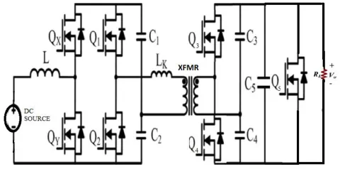
The circuit diagram of the proposed system as in FIGURE (2) includes Variable speed wind turbine, Permanent magnet synchronous generator, power electronic components which includes rectifier, inverter, boost converter and the control system which is a PI controller. The description of the circuit diagram parameters are described in the following sections.
FIGURE 2: CIRCUIT DIAGRAM OF THE PROPOSED SYSTEM
The proposed system is an interleaved boost converter which steps up 12V DC from the wind to 230V AC suitable for residential power system. The soft-switching technique is used to reduce the switching losses leading to better efficiency. The Zero Current Switching of primary side switches and Zero Voltage Switching of secondary side devices is achieved. Hence soft-switching of all semiconductor devices is achieved. Soft-switching is inherent and is independent of load. The 12V DC from the wind is converted to AC and given to transformer using interleaved boost converter. Interleaved topology is known for its high power level operation and reduced ripple content. It uses MOSFET switches because of its high frequency operation. The transformer is used for stepping up the voltage and for isolation purpose. The stepped-up AC voltage is converted to DC using rectifier. Hence the front end DC-DC converter is a three stage conversion which has high step-up, high efficiency and low cost. The tip speed ratio of a wind turbine is a variable expressing the ratio between the peripheral blade speed and the wind speed. It is denoted by λ and computed
as below,
R
v
(1)Where R is the blade length, is the rotor speed, v is the wind speed and the power extracted by a wind turbine whose blade length is R is expressed as,
2
1
2
T P
P
R
C
(2)Therefore,
C
P
4 (1
a
a
)
2 (3)The maximum value of
C
P occurs for1
3
Vol. 4, Issue 3, March 2015
c. RESONANT CONVERTERS
Resonant converters use a resonant circuit for switching the transistors when they are at the zero current or zero voltage point, this reduces the stress oni the switching transistors and the radio interference. We distinguish between ZVS and ZCS resonant converters (ZVS: Zero Voltage Switching, ZCS: Zero Current Switching). To control the output voltage, resonant converters are driven with a constant pulse duration at a variable frequency. The pulse duration is required to be equal to half of the resonant period time for switching at the zero-crossing points of current or voltage. There are many different types of resonant converters. For example the resonant circuit can be placed at the primary or secondary side of the transformer. Another alternative is that a serial or parallel resonant circuit can be used, depending on whether it is required to turn off the transistor, when the current is zero or the voltage is zero. The technique of resonant converters is described below giving the ZCS-push-pull resonant converter as an example.
d. PI CONTROLLER
Various methods have been applied to evaluate the performance of point forecasts. Out of these methods, the most popular ones are error-based measures, such as mean square errors (MSEs) and mean absolute percentage errors (MAPE). Likewise, the quality of PIs needs to be quantitatively evaluated. In this section, evaluation indices for both the coverage probability and width of PIs are initially introduced. Specially, a new index for width evaluation is proposed. The new index is suitable for training NN models. Finally, a cost function for the comprehensive evaluation of PIs is developed.
PI COVERAGE PROBABILITY
Usually, the coverage probability (or confidence level) is considered as the key feature of PIs. PI coverage probability (PICP) shows in which probability target values will be covered by the upper and lower bounds. A larger PICP means more targets lie within the constructed PIs and vice versa. PICP is defined as follows:
1
1
N i iPICP
N
(4)Where N is the number of samples and is a Boolean variable, which shows the coverage behavior of PIs. If the target value yi is covered between the lower bound
L
i and upper boundU
i,
i
1
otherwise
i
0
. Mathematically, _i is defined as follows:1,
[L , U ]
0,
[L , U ]
i i i
i
i i i
ify
ify
(5)To have valid PIs, PICP should not be less than the nominal confidence level of PIs. Otherwise, PIs are invalid and should be discarded. The ideal case for PICP is PICP = 100%, which means all the targets are covered by PIs. B. PI Normalized Average Width and PI Normalized Root-Mean-Square Width The quality of PIs is often evaluated by PICP and discussion about the width of PIs is either ignored or vaguely presented. If the upper and lower bounds of PIs are chosen as extreme values of the targets (maximum and minimum values),a high PICP (even 100% PICP) can be easily achieved. Width of PIs determines their informativeness. In the literature, a quantitative measure of the width is defined as PI normalized average width (PINAW)
1
PINAW
NR
(6)Where R is the range of the underlying targets([maximum minus minimum). The purpose of using R is to normalize the PI average width in percentage.
2
(U
i
L )
i (7)Vol. 4, Issue 3, March 2015
e. ZERO CURRENT SWITCHING
Zero-current switching as shown in FIGURE 2, the transistor turn-off transition occurs at zero current. Zero-current switching eliminates the switching loss caused by IGBT current tailing and by stray inductances. It can also be used to commutate SCR’s. For the most part, it can be considered as square wave power utilizing a constant off-time control which varies the conversion frequency, or on-time to maintain regulation of the output voltage. For a given unit of time, this method is similar to fixed frequency conversion which uses an adjustable duty cycle, as shown in FIGURE 4. Regulation of the output voltage is accomplished by adjusting the effective duty cycle, performed by varying the conversion frequency. This changes the effective on-time in a ZVS design. It is virtually identical to that of square wave power conversion, and vastly unlike the energy transfer system of its electrical dual, the zero current switched converters. During the ZVS switch off-time, the L-C tank circuit resonates. This traverses the voltage across the switch from zero to its peak, and back down again to zero. At this point the switch can be reactivated, and lossless zero voltage switching facilitated. Since the output capacitance of the MOSFET switch, it has been discharged by the resonant tank, it does not contribute to power loss or dissipation in the switch.
Therefore, the MOSFET transition losses go to zero-regardless of operating frequency and input voltage. This could represent a significant savings in power, and result in a substantial improvement in efficiency. Obviously, this attribute makes zero voltage switching a suitable candidate for high frequency, high voltage converter designs. Additionally, the gate drive requirements are somewhat reduced in a ZVS design due to the lack of the gate to drain (Miller) charge, which is deleted when voltage equals zero. The technique of zero voltage switching is applicable to all switching topologies; the buck regulator and its derivatives (forward, half and full bridge), the fly back, and boost converters, to name a few. Zero-Voltage Switching, the transistor turn-on transition occurs at zero voltage. Diodes may also operate with zero-voltage switching. Zero-voltage switching eliminates the switching loss induced by diode stored charge and device output capacitances. Zero-Voltage Switching is usually preferred in modern converters. Zero-Voltage Transition converters are modified PWM converters, in which an inductor charges and discharges the device capacitances. Zero-Voltage Switching is then obtained.
IV. EXPERIMENTAL RESULTS
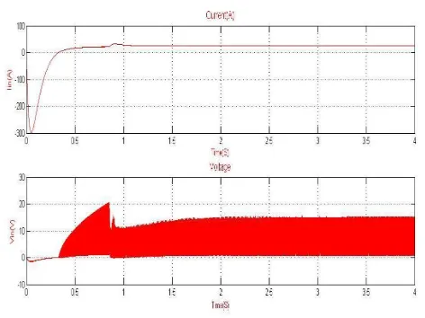
FIGURE 3: OUTPUT CURRENT AND VOLTAGE OF WECS
Vol. 4, Issue 3, March 2015
FIGURE 4: RECTIFIER DC CURRENT AND VOLTAGE
FIGURE 4 shows the rectified DC voltage from the transformer. The output current is 0.465A. the output voltage is 230V DC. The interleaved DC to Dc converter is a three stage converter. Thus a 12V DC is stepped up to 230V DC using step up transformer.
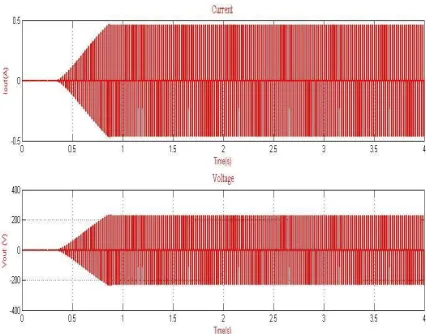
FIGURE 5: INVERTER AC OUTPUT CURRENT AND VOLTAGE
FIGURE 5 shows the inverter AC voltage taken at the inverter terminal. The output current is 0.465A. the output voltage is 230V AC suitable for residential power system.
Vol. 4, Issue 3, March 2015
FIGURE 6 shows the primary switch voltage and current waveform. Zero Current Switching of primary side switches is obtained by resonant technique. Thus the switching losses are significantly reduced leading to higher efficiency.
V. CONCLUSION
This paper proposes a design of wind energy source with interleaved resonant converter for power conversion system. The boost converter with interleaved topology increases the power level and minimizes the current ripple. The conventional boost converter has the major problem of hard switching which increases switching losses. The proposed secondary modulation achieves the soft-switching of all semiconductor devices (ZCS of primary device) without modifying the topology. Switching losses is reduced due to soft-switching leading to high efficiency. Soft-switching is inherent, independent of the load and is maintained with variation in source voltage. Soft-switching permits high switching frequency operation leading to design compact, low cost, light weight system and high efficiency over wide range of load and input voltage.
REFERENCES
[1]. Jiawei Chen, Jie Chen and Chunying Gong, “On optimizing the transient load of variable-speed wind energy conversion system during the MPP tracking process” IEEE transactions on industrial electronics, vol. 61, no. 9, September 2014
[2]. N. Krishna Swami Naidu, Bhim Singh, “Sensorless control of singlevoltage source converter-based doubly fed induction generator for variable speed wind energy conversion system IET power electron” vol. 7, iss. 12, pp. 2996–3006 doi: 10.1049/iet-pel.2014.0034.
[3]. A.Mesemanolis, C. Mademlis and I. Kioskeridis, “Maximum electrical energy production of a variable speed wind energy conversion system” 2012 IEEE.
[4]. Jiawei Chen, Jie Chen and Chunying Gong, “New overall power control strategy for variable-speed fixed-pitch wind turbines within the whole wind velocity range”, IEEE transactions on industrial electronics, vol. 60, no. 7, July 2013.
[5]. Mohammed Sowket Ali, Seoul, Chang Reung “Design of a maximum power point tracking system of a wind turbine for battery”, vol. 2 no. 2 May-July 2012 158.
[6]. Youssef. Errami, Mohamed. Maaroufi Mohammed. Ouassaid “Control scheme and maximum power point tracking of variable speed wind farm based on the pmsg for utility network connection” 2012 IEEE