c e-ISSN: 2348-6848, p- ISSN: 2348-795X Volume 3, Issue 01, January 2016
International Journal of Research (IJR)
Available at http://internationaljournalofresearch.orgAnalysis of LFC-Dr Model for Single Area Power System
1
C.Ghalib Khan &
2M.Subramanyam
1
M.Tech Student, Dept. of EEE, SIR C.V.RAMAN Institute of Technology & Sciences, Affiliated to
JNTUA
2
Assistant Professor in Dept. of EEE, SIR C.V.RAMAN Institute of Technology & Sciences, Affiliated
to JNTUA
Abstract: Demand Response (DR) is becoming an integral part in the power system and market operations. Much research work is going on the impact of demand response on power system dynamic performance, especially on load frequency control (LFC) problem. The effect of communication delay and optimal operation through optimal power sharing between DR and supplementary control is considered in controller design. The objective of this paper is to fill this gap by introducing a DR control loop to the conventional LFC model single area power system. The addition of the DR control loop increases the stability margin of the system and DR effectively improves the system dynamic performance. The proposed method simulation studies are carried out for a single area power system to verify its effectiveness.
Keywords: Demand response (DR); load frequency control; single area power system; steady state error; sensitivity; stability.
I. INTRODUCTION
Demand response (DR) has an important role to play in the electricity market by introducing load flexibility instead of adjusting only generation levels, at all the operation time scales to maintain the balance between supply and demand. There are many players in the market who benefit from DR, like the TSO, DSOs, retailers and end customers themselves. The recent arrival of smart grid technologies by providing the needed information and communication infrastructure to the existing
grid advanced the integration of DR. “Changes in
electric usage by end-use customers from their normal consumption patterns in response to changes in the price of electricity over time, or to incentive payments designed to induce lower electricity use at times of high wholesale market prices.”
Conventionally, by balancing the generation and demand frequency regulation is achieved in power system through load following, i.e., spinning and non-spinning reserves [1]. It is foreseen; in future there will be high penetration of renewable energy (RE) power generation in the power grid, which can be highly variable. In such cases for balancing generation and demand, energy storage and responsive loads show great effort, and also avoid the use of the traditional generation schemes, which are costly and/or environ-mentally unfriendly.
Once DR reaches a definite threshold, It very hard to ignore the effects of DR on the distribution and transmission system. Demand response (DR) is considered for balancing power in real time smart responsive load participation with the limited availability, low efficiency, and high cost of large storage devices. It is known that DR manages the uncertainty and variability of some renewable resources by increases system reliability and flexibility, reduces cost of operation, and intensify system the carry-flow adder (CFA) was mainly an improved RCA in which detrimental wires effects were mitigated efficiency.
c e-ISSN: 2348-6848, p- ISSN: 2348-795X Volume 3, Issue 01, January 2016
International Journal of Research (IJR)
Available at http://internationaljournalofresearch.orgextra capacities from large generators and
interconnection [1]. From the last five decades basically, the Single area power system consists of a governor, a turbine and a generator with feedback of regulation constant. System also includes step load change input to the generator. These models help to study small variations in load and generation, and in controller design. In this paper a DR control loop is introduced to the LFC model called “LFCDR”. By introducing this control loop the general small signal model of a power system used in LFC studies is modified. Other goals of the paper is to include communication delay associated i.e., joined with DR between the load aggregator companies (Lagcos) and the end use consumers devices to make the model as general as possible. This is an important parameter in the system dynamic performance of LFC-DR. The communication delay between the balancing authority (BA) and the load aggregators (Lagcos),and between the BA and generation companies (Gencos) are assumed to be same.
As the focus of this paper is only on the assessment of the DR loop in the LFC model the above delays are not considered. Based on the real time market price, the proposed LFC- DR gives an opportunity to the system operator to choose the DR option or spinning/non-spinning reserve, or a combination of the two. Also, to estimate the actual value of the required responsive load manipulation of the disturbance is unknown to the system operator the LFC-DR model can be used. To study the importance of the dynamic performance of a power system with DR to provide AS is another initiative determination. With the help of LFC - DR model the operators investigates the impact of DR on the dynamic performance of the system prior to its usage, and during the automatic generation control (AGC) design process. The model is developed for single area power system by using the concept of LFC-DR. The model is analytically evaluated. Finally, the controller design is presented, and simulation results are given.
II. SINGLE AREA POWER SYSTEM
PROBLEM FORMULATION
For the purpose of frequency control synthesis and
Analysis a general low order linearised power system model is given by the power balance equation in the frequency-domain.
Δ PT(s) –Δ PL(s) = 2H.s.Δ f(s) + D.Δ f(s) (1) Where as
Δ PT(s) – Δ PL(s) - mismatch in incremental power; Δ f(s) - deviation in frequency;
2H - equivalent inertia constant; D - load damping co-efficient; s - laplace transform operator.
Since DR for AS performs like spinning reserve in magnitude and power flow direction, i.e., if once frequency deviation is positive(negative), it is required to turn ON(OFF) a portion of the responsive loads (i.e., DR), the effect of DR has been included in the load-damping coefficient D. We believe as the D is an inherent parameter and is not controllable, but where as DR is an intentional controllable signal of the system so the effect of DR should be separated. In addition, (2) will consent to have a separate control loop for DR, which is more realistic and provide a better structure for controller design. A simplified non-reheat steam turbine block diagram for single area power system with a simplified non-reheat is shown in Fig.1, feed-back control loop for DR is also shown. Where T is the equivalent speed governor and Tt is turbine time constants respectively, R is the equivalent droop value, and Td is the equivalent DR delay. The parameters of the system can be the equivalent of all generation assets and load damping of the same area. The main idea of this paper is conveyed by using this model unlike the usual spinning reserve provider power lands, there is no ramp up and down limitations on the DR resources. In other words, by
receiving the command signal the power
consumption status of controllable loads can be changed instantaneously. Therefore, communication delay which is known as latency is the only obstacle for DR (disregarding the aggregation of small loads), which affects the system dynamic performance.
A. LFC-DR Model with State Space Representation
c e-ISSN: 2348-6848, p- ISSN: 2348-795X Volume 3, Issue 01, January 2016
International Journal of Research (IJR)
Available at http://internationaljournalofresearch.organalysis and conclusions can be extended to other types of turbines, such as hydro and as well as reheat-steam turbine. The state-space realization of a single-area power system with DR (shown in Fig. a) is given by
ẋ(t) = A. x(t) + B. u(t) + Γ. ѡ(t)
y(t) = C. x(t) (3)
Where is the system matrix, is the control input matrix, is the disturbance matrix, is the state vector, is the input vector, is the disturbance variable, is the observation matrix, and is the system output. A linear model of the system is required to derive the linear state-space model of the system. The system consists of only one nonlinear element i.e., the time delay in the DR control loop it is clearly seen in fig .1. Therefore, to derive state space model to linearization of time delay is needed. In following subsection Pade approximation, is explained which is used for linearzing the DR time delay.
B. pade approximation
To linearize systems with time delays in control engineering with very strong convergent results the pad approximation is widely used. By quotients of polynomials it basically approximates time delays. Where Td is the DR communication latency. With the above approximation of time delay nonlinearity, the state space representation of the system (3) has the matrices, where T is the transpose operation of matrices. For the power system which is more complicated, a new power system model presented is with the upper left partition of matrix A, and the left partitions of other matrices can be modified. Based on the order of new power system model the other partitions of the matrices should be properly resized.
III. ANALYTICAL EVALUATION OF THE MODEL
In this section, the steady-state error evaluation, sensitivity analysis, and stability of the system by using LFC model with and without the DR control loop are presented.
A. Steady State error evaluation
The primary control loop which is known as frequency droop loop in Fig. 1, it is the fastest intentional control action done in a power system but it is not enough to make the frequency deviation go to zero at steady-state. Due to this reason, the supplementary frequency control loop is necessary
for the further control, as shown in Fig. a. Therefore, it is necessary to examine the impact of the DR control loop on the steady-state error of the given power system in Fig. a. Later in this subsection, based on optimal sharing between DR and supplementary control loops, a synthesis of controller design will be derived from the steady state error evaluation. The steady-state equations of conventional LFC are well-documented in e.g. [13], [11].
The system frequency deviation can be expressed as below after Adding the DR control loop to the conventional LFC model: Δf(s)= 1 It can be seen that unless supplementary and DR control exist the frequency deviation will not be zero i.e., from (9). Also, DR control loop provides an extra degree of freedom for System frequency regulation. In addition, the following conclusions can also be drawn from (9):
• The steady state error is independent on the delay and the order of its approximation.
• Frequency regulation with high reliability can be achieved through DR available in the LFC, since the DR control loop can complement the supplementary control loop. In the case when the supplementary control is not available, if enough DR resources are available the performance of the frequency regulation can be guaranteed by the DR loop.
• In order to have steady state frequency deviation to zero, the required control effort can be split between the supplementary control loop and DR control loops. Perform the regulation services in cost effective way and also to quickly analyse the frequency response of the system, an ISO/RTO will have the opportunity. Further discussion to the last conclusion is: By considering a situation where there is no DR available. If ΔPS.SS=ΔPL the frequency error will be zero at steady state. It means during disturbance, the required spinning and/or non spinning reserves are provided by the supplementary control. The required control effort in this study is split between two control loops based on real time electricity market cost when DR available in the LFC:
c e-ISSN: 2348-6848, p- ISSN: 2348-795X Volume 3, Issue 01, January 2016
International Journal of Research (IJR)
Available at http://internationaljournalofresearch.orgtraditional regulation services, i.e like spinning and non-spinning reserve, and α=0 is for the time when all the required control would be provided by DR. Based on the traditional regulation services in real time market and on the price of DR the ISO/RTO decides the value of α, explored by the authors in [10]. Then, it is possible by the ISO/RTO to effectively and quickly assess the different scenarios of LFC and also to evaluate the system performance under various circumstances. Finally, the steady state value of the two inputs should be
B. Sensitivity analysis for the feedback system with and without DR
To study the impact of the DR control loop on the overall sensitivity of the closed loop system with respect to the open loop system an analytical method is utilized. It is to measure the sensitivity of the closed loop system with respect to the co-efficient. The robustness of the closed loop system
performance when system performances are
subjected to any variations is shown in the first sensitivity analysis, it is quite important. Since then is also a very important parameter in the performance of LFC-DR model, second sensitivity analysis is also necessary.
By using a single integral controller for both DR control loop and supplementary control loop the power system is modeled. This will helps to split the control effort between the two control loops(i.e., DR and supplementary control loops). For example when α=0.8, 80% of required regulation is provided by the supplementary control loop and remaining 20% by using the DR control loop. The simulation study is carried for an arbitrary integral feedback gain to compare the sensitivity function. As α is an important parameter to evaluate the sensitivity of Closed loop system. Frequency deviation is decreased by about 42.5%. The results show improvement in the settling time as well. The same simulation was repeated for α=0.8. As expected, the lower DR control effort resulted in less improvement in the system dynamic performance. It can be observed that the dynamic performance of the system approaches that of conventional LFC for higher values of α.
p
.u
input
s,
Supplementary, alpha=0.8
5
SS=0.8x0.01= 0.008 p.u
Cont
rol
4 Supplementary,
alpha=0.1
DR loop,
alpha=0.8
SS=0.2x0.01= 0.002 p.u
SS=0.1x0.01= 0.001 p.u
3
2
1
00 1 2 3 4 5 6 7 8 9 10 Time (s)
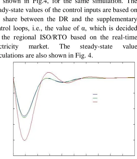
Fig. 4. Steady-state values of the control inputs for the LFC-DR model
The supplementary and DR control inputs are shown in Fig.4, for the same simulation. The steady-state values of the control inputs are based on the share between the DR and the supplementary control loops, i.e., the value of α, which is decided by the regional ISO/RTO based on the real-time
electricity market. The steady-state value
calculations are also shown in Fig. 4.
Fig. 5. Controller performance for different order of Padé
approximation
c e-ISSN: 2348-6848, p- ISSN: 2348-795X Volume 3, Issue 01, January 2016
International Journal of Research (IJR)
Available at http://internationaljournalofresearch.orgFig.5 that the results from the 2nd and 5th order Pade approximation are almost identical. It is mainly because the simplified governor and turbine models are low pass filters which restrict the system response to lower frequency ranges, where Pade approximation is exactly the same as pure time delay. Therefore, for simplicity, 2nd order Pade approximation can be employed for more complicated power systems without negative impacts on the final results.
The two control inputs are unified as a single input for the controller design as a function of α.
2 x 10⁻³
0
u2 = F(u1)
-2 u1 = F (u2)
Hz -4
d
ev
ia
ti
o
n
,
-6
F
re
q
ue
n
cy
-8
-10
-12
-140 2 4 6 8 10 12 14 16 18 20
Time (s)
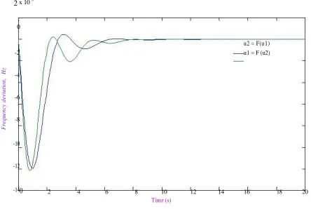
Fig.6. Impact of different unified inputs on the performance of the LFC-DR model
The control input unification can be done in two ways: unifying u1(t) as a function of u2(t) or vice versa [
( ) or ( ) ]. To show the impact of
unification, a simulation study was carried out to compare the performance of the system for both unification cases, and the results are shown in Fig.6.
It can be observed that the difference between the two unifying approaches is negligible. In other words, the unifying control input can be chosen arbitrarily without any negative impact on the performance of the LFC-DR model.
One significant feature of the proposed LFC-DR model is the possibility for the ISO/RTO to evaluate the impact of communication delay of the DR control loop on the system performance for frequency stabilization. In order to show the impact of latency, a simulation study was performed for different values of communication latency for α=0.1. Simulation results are shown in Fig.7.
The lowest communication delay (lowest) is for a small power system with fast two-way communication link,
such as wireless communication, between the Lagcos and individual loads. It can be seen that the LFC-DR model gives a better performance compared to the conventional LFC when .
When the time delay exceeds 0.2 sec, it deteriorates the performance of the LFC-DR, and the response is even worse than that of conventional LFC for . This is not surprising since the
single-area power system under study has a very fast dynamic response. In larger power systems with generation rate limiters and slow turbine-governor systems, a slower dynamic behavior would be expected from the supplementary control. But, the LFC-DR will keep its superior performance even for higher communication latencies
0.5 x 10⁻³
0
-0.5
Hz
-1
Td=0.1 sec
d
ev
ia
ti
o
n, -1.5 Td=0.3 sec
Td=0.5 sec
-2 Conventional LFC
F
re
q
u
en
cy
-2.5
-3
-3.5
-4
-4.50 2 4 6 8 10 12 14 16 18 20
Time (s)
Fig.7.Impact of DR latency on the performance of a slower single-area power system
To show the impact of the DR latencies on a larger power system with high inertia and slower response, another simulation study was conducted with the parameters given in Table II. It can be seen from Fig.8 that for a larger and consequently slower power system, the performance of the LFC-DR model is superior to that of conventional LFC even for larger communication latencies.
TABLE II :Font Sizes for Papers Power System Parameters For The Simulation Study
Tg Tt R 2H D ΔPL
0.3sec 0.8sec 2.4Hz/p.u 3.0 0.0083 0.01p.u. pu p.u./Hz
c e-ISSN: 2348-6848, p- ISSN: 2348-795X Volume 3, Issue 01, January 2016
International Journal of Research (IJR)
Available at http://internationaljournalofresearch.orgIt has been shown in [6] that even with the current Internet infrastructure; a latency of 500msec can be achieved easily. Therefore, it can be concluded that the DR with the largest available latency (500 msec) still can be effective for large power systems.
The proposed method is explained and compared with the conventional method using simulation results. The proposed method validated through simulation results for the different cases.
V. CONCLUSION
The proposed LFC-DR model responds to all frequency deviations as is the case in the traditional LFC model. However, if it is desired to prevent the LFC-DR model to respond to small frequency deviations, and also keep the linearity of the model, a dead band could be added to the input. This is because of the fast dynamics of the common variable generation (wind, solar PV) compared to those of traditional power plants in the LFC model.
In this thesis, investigate the effectiveness of the LFC-DR model for frequency regulation at the transmission level in a single-area power system. However in general, large power systems are multi-area where different Gencos and Lagcos are available in each area. In this thesis, a general framework is proposed to include DR into the LFC problem (LFC-DR). The proposed formulation can be expanded easily for any type of power system in size and characteristics. The framework adapts
real-time electricity market with existing load
aggregators. It balances the power between generation and demand and stabilizes the system frequency by utilizing a percentage of available
controllable loads and/or conventional
supplementary control, based on the real-time market price. It also includes communication latencies in DR for controller design, using pade approximation. It is shown through different analytical studies that the proposed LFC-DR framework will improve the stability margins in the conventional LFC model and is slightly less sensitive to the variation in the system parameters, such as changes in the open-loop transfer function. Similar results have also been obtained for the sensitivity of the closed-loop system with respect to the parameter. Simulation results show the
effectiveness of the LFC-DR model in improving stabilization of the system frequency
REFERENCES
[1] R. Doherty and M. O’Malley, “A new approach to quantify reserve demand in systems with significant installed wind capacity ,” IEEE Trans. Power Syst., vol. 20, no. 2, pp. 587–595, May 2005.
[2] A. Brooks, E. Lu, D. Reicher, C. Spirakis, and B. Weihl, “Demand dispatch: Using real-time control of demand to help balance generation and load ,” IEEE Power Energy Mag., vol. 8, no. 3, pp. 20–29, May/Jun. 2010.
[3] M. Parvania and M. Fotuhi-Firuzabad, “Integrating load reduction into wholesale energy market with application to wind power integration,” IEEE Syst. J., vol. 6, no. 1, pp. 35–45, Mar. 2012.
[4] K. Dietrich, J.M. Latorre, L. Olmos, and A. Ramos, “Demand response in an isolated system with high wind integration,” IEEE Trans. Power Syst., vol. 27, no. 1, pp. 20–29, Feb. 2012.
[5] S. A. Pourmousavi and M. H. Nehrir, “Demand response for smart micro grid: Initial results,” in Proc. 2nd IEEE PES Innov. Smart Grid Technol. (ISGT), Anaheim, CA, USA, 2011, pp. 1–6.
[6] S. A. Pourmousavi, M. H. Nehrir, and C. Sastry, “Providing ancillary services through demand response with minimum load manipulation,” in Proc. 43rd North Amer. Power Symp. (NAPS), Boston, MA, USA, 2011, pp. 1–6.
[7] D. Trudnowski, M. Donnelly, and E. Lightner, “Power-system frequency and stability control using decentralized intelligent loads,” in Proc., IEEE PES Conf. Exhib. Transm. Distrib., Dallas, TX, USA, 2005, pp. 1453–1459.
[8] A. Molina-García, F. Bouffard, and D. S. Kirschen, “Decentralized demand-side contribution to primary frequency control,” IEEE Trans. Power Syst., vol. 26, no. 1, pp. 411–419, Feb. 2011.