ISSN (Print) : 2320 – 3765 ISSN (Online): 2278 – 8875
I
nternational
J
ournal of
A
dvanced
R
esearch in
E
lectrical,
E
lectronics and
I
nstrumentation
E
ngineering
(An ISO 3297: 2007 Certified Organization)
Vol. 5, Issue 8, August 2016
Simulation of Renewable Based Standalone
System for Smart Mini Grid Applications
Anas Kamal1, Mohd Ilyas2,
M.Tech Student (Power System), Dept. of EEE, Al-Falah University, Faridabad, Haryana, India1
Assistant Professor, Dept. of EEE, Al-Falah University, Faridabad, Haryana, India2
ABSTRACT: The paper proposes a method of modelling and simulation of Solar Photovoltaic arrays (SPY), interface between two dissimilar toolboxes in MATLAB and different control schemes for the converter control.The main objective is to perform the analysis of the renewable based standalone system for smart mini grid applications by developing a hybrid model.The method finds the I-V output waveform for the single diode photovoltaic model including the effect of the series and parallel resistances. Simulation of the standalone system has been carried out using two different DCDC converters one with push pull converter topology and the full bridge converter topology. A PWM inverter model has been used for the complete model simulation. Finally, hybrid model have been developed so as to perform the analysis of the renewable based standalone system for smart mini grid applications.
KEYWORDS: Solar Photovoltaic Arrays, DC-DC Converters, PWM Inverter, Modeling, Hybrid System, Smart Mini Grid.
I.INTRODUCTION
A solar array has been built in MATLAB using Sims cape toolbox. The I-V curves are generated for variations cell temperatures and solar irradiance level. The output of the SPY is then fed to the DC-DC converter. As the voltage generated by the SPY is more, buck topology is used for the converter. The converter has been designed in two methodologies, Push pull as well as in full bridge. The complete model simulation has been done in MATLAB using two different toolboxes. For modeling the Solar Photovoltaic arrays (SPY),MATLAB/Sims cape has been used and in order to model the converter-inverter part MATLAB/Sims Power Systems toolbox have been used. As two dissimilar toolboxes are used there should be an interface between them. The hybrid model has been developed by making use of the available resources. The battery which is available in the MATLAB has been considered for the hybrid system. This paper also presents the interface between these two toolboxes which makes the task easier for analysis and for the simulation environment.
II.METHODOLOGY
The variations in insulation and cell temperature are considered in simulation. Modeling of the converter has been done by considering the voltage and current ripples. The output of the converter of solar photovoltaic system is designed to obtain constant 380V DC output which is to be across the PWM inverter for generating 230V.The closed loop system responses of the converters are compared with two different methods. One on primary side control and another on the secondary side control of the converter. The different responses of the system are furnished in the later parts of this paper. The suitable method of control has been suggested as per the obtained response.
ISSN (Print) : 2320 – 3765 ISSN (Online): 2278 – 8875
I
nternational
J
ournal of
A
dvanced
R
esearch in
E
lectrical,
E
lectronics and
I
nstrumentation
E
ngineering
(An ISO 3297: 2007 Certified Organization)
Vol. 5, Issue 8, August 2016
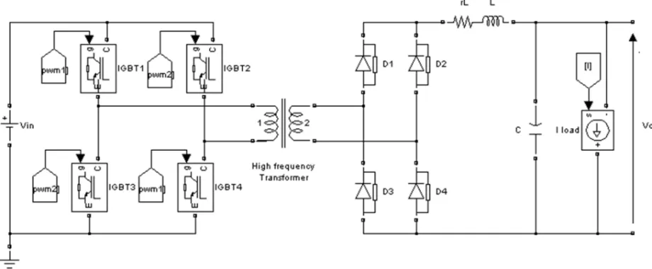
Fig 1: Standalone SPY System with Push Pull DC-DC Converter
ISSN (Print) : 2320 – 3765 ISSN (Online): 2278 – 8875
I
nternational
J
ournal of
A
dvanced
R
esearch in
E
lectrical,
E
lectronics and
I
nstrumentation
E
ngineering
(An ISO 3297: 2007 Certified Organization)
Vol. 5, Issue 8, August 2016
Fig 3: Subsystem for Wind Model in Hybrid System
ISSN (Print) : 2320 – 3765 ISSN (Online): 2278 – 8875
I
nternational
J
ournal of
A
dvanced
R
esearch in
E
lectrical,
E
lectronics and
I
nstrumentation
E
ngineering
(An ISO 3297: 2007 Certified Organization)
Vol. 5, Issue 8, August 2016
Fig 5: Hybrid system
The above figure's 1 and 2 represents the complete model simulation circuit of SPY System with two different converter topologies. The modeled converters are connected to the solar photovoltaic module and the inverter with their filter at respective levels. LC filters are used at lateral stages of the subsystems, so as to maintain the voltage levels. The closed converters are modeled using PI controller. The gain values have been chosen using Ziegler-Nicholas method.PI controller is used to make the converter closed loop. The open loop responses of the complete stand Alone system are observed and the considerable changes are noticed in the closed loop control. The following figure 3 represents the subsystem of a Wind Model in hybrid system. The mathematical model of the wind turbine and a dc dc converter were developed as per the standard requirements. Figure 4 represents the subsystem of the SPY in the hybrid system. Figure 5 represents the interconnection of the two intermittent renewable resources.
III. SIMULATION RESULTS
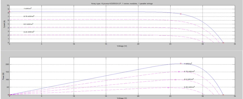
The simulation results are analyzed at different instances. The I-V & P-V curves of the SPY are furnished in the figure 6 where we can observe the variation w. r. t solar irradiance level and the cell temperature. The modules have been modeled using the MPPT algorithm to obtain the maximum power. The comparison of the model with and without MPPT results are shown in the later instances of the paper along with the modeled converters.
ISSN (Print) : 2320 – 3765 ISSN (Online): 2278 – 8875
I
nternational
J
ournal of
A
dvanced
R
esearch in
E
lectrical,
E
lectronics and
I
nstrumentation
E
ngineering
(An ISO 3297: 2007 Certified Organization)
Vol. 5, Issue 8, August 2016
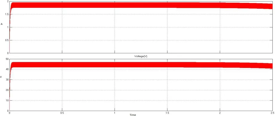
Fig 7: Output Voltage and Current from the SPY System
A. Open Loop Push Pull DC-DC Converter Output Voltage and Current in MATLAB: The open loop output voltage and current response of the push pull converter is trailing in fig 8. The model has been analyzed in terms of settling time, percentage peak overshoot and the damping of the system.
Fig 8: Output Voltage & Current of Open Loop Push Pull Converter
ISSN (Print) : 2320 – 3765 ISSN (Online): 2278 – 8875
I
nternational
J
ournal of
A
dvanced
R
esearch in
E
lectrical,
E
lectronics and
I
nstrumentation
E
ngineering
(An ISO 3297: 2007 Certified Organization)
Vol. 5, Issue 8, August 2016
Fig 9: Output Voltage & Current of Closed Loop Push Pull Converter
When comparing the open loop and closed loop responses of the push pull converter, as shown in figure 8 and 9 it can be clearly seen the over damped system has become a critically damped and the settling time has come down drastically. The primary side control is more effective when compared to the secondary side control as far as the settling time is concerned. The secondary side control figure 7 which is trailing below.
C. Open Loop Full Bridge DC-DC Converter Output Voltage and Current in MATLAB :The open loop output voltage and current response of the full bridge converter can be observed in fig 10. The model has been analyzed in terms of settling time, percentage peak overshoot and the damping of the system.
ISSN (Print) : 2320 – 3765 ISSN (Online): 2278 – 8875
I
nternational
J
ournal of
A
dvanced
R
esearch in
E
lectrical,
E
lectronics and
I
nstrumentation
E
ngineering
(An ISO 3297: 2007 Certified Organization)
Vol. 5, Issue 8, August 2016
D. Closed Loop Full Bridge DC-DC Converter Output Voltage and Current in MATLAB:When comparing the open loop and closed loop responses of the full bridge converter as shown in the figure 10 and 11, it can be clearly seen the settling time has come down considerably. There is no much change as that of in push pull converter.
Fig 11: Output Voltage & Current of Closed Loop Full Bridge Converter
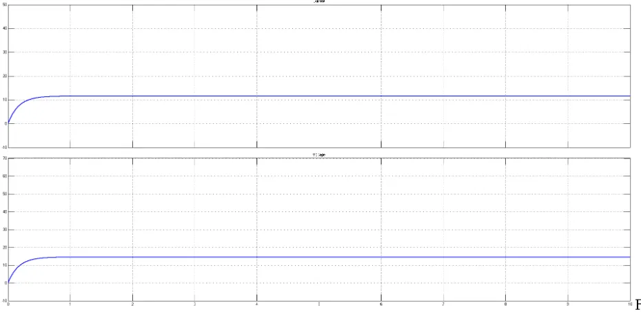
E. Standalone System Output Voltage & Current of SPY & WTG in MATLAB:The individual output voltages of the SPY and WTG can be clearly observed in the figure 12. In figure 13 the output voltage of SPY and WTG contribution towards the battery can also be observed.
ISSN (Print) : 2320 – 3765 ISSN (Online): 2278 – 8875
I
nternational
J
ournal of
A
dvanced
R
esearch in
E
lectrical,
E
lectronics and
I
nstrumentation
E
ngineering
(An ISO 3297: 2007 Certified Organization)
Vol. 5, Issue 8, August 2016
Fig 13: Output Voltage of SPY & WTG to Battery
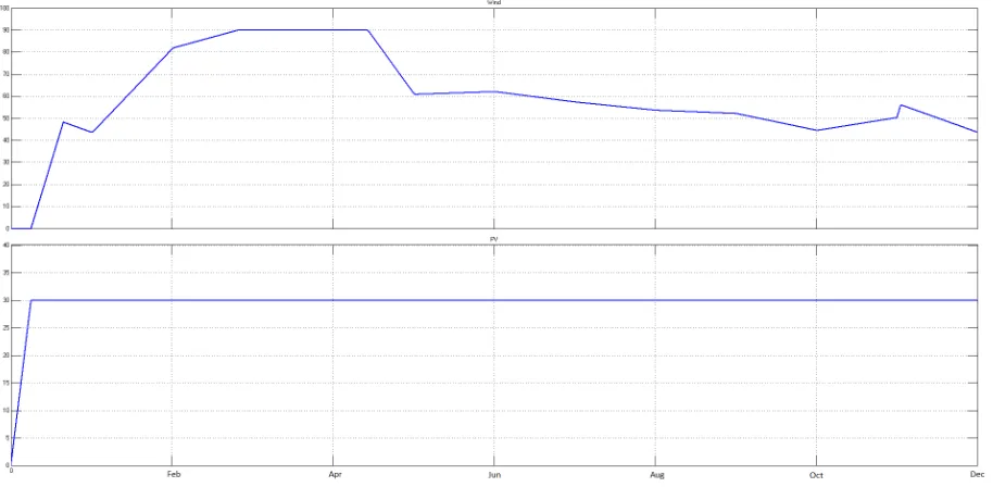
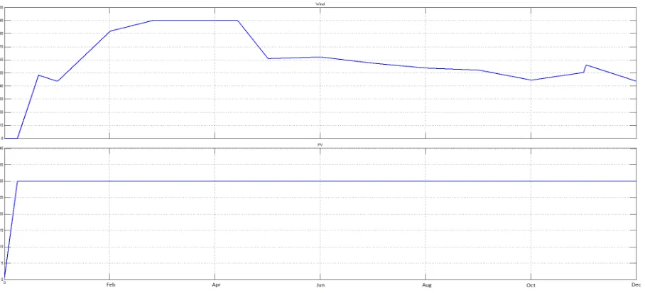
F. Hybrid System Output Voltage & Current with Different converters in MATLAB:It is observed from the figure 14 and in 15; when using either push pull or full bridge the output from the PWM inverter is 230V AC which can be used to feed the single phase load.
Fig 14: Complete Model Simulation with Push Pull Converter
ISSN (Print) : 2320 – 3765 ISSN (Online): 2278 – 8875
I
nternational
J
ournal of
A
dvanced
R
esearch in
E
lectrical,
E
lectronics and
I
nstrumentation
E
ngineering
(An ISO 3297: 2007 Certified Organization)
Vol. 5, Issue 8, August 2016
V. CONCLUSION
Finally the standalone Solar Photovoltaic System simulation in MATLAB with two different converter topologies and control methods are shown in the paper. It is observed that the primary side control is giving a better response when compared to the secondary side control of the transformer in the converters. The paper also has the simulation result of the responses of a hybrid system. The output voltage of the SPY and WTG are furnished.
REFERENCES
[I] TERI and SEC, "Indian Mini-grid-Scoping and Initial design", Indian Mini-grid-Scoping and Initial design, February 20 I 0, [I -I 5]
[2] ROBERTO FARANDE, SONIA LEVA, Energy Comparison of MPPT techniques for PV Systems, WSEAS Transactions on Power Systems, vol.3, no.6, June 2008.
[3] G. R. Walker and J. C. Pierce. Photovoltaic dc-dc module integrated converter for novel cascaded and bypass grid connection topologies design and optimisation. IEEE Power Electronics Specialists Conference, June 2006.
[4] G. R. Walker and P. C. Sernia. Cascaded dc-dc converter connection of photovoltaic modules. Volume 19, pages 1130, 1139. IEEE Transactions on Power Electronics, July 2004.
[5] G. R. Walker, J. Xue, and P. Sernia. PV string per-module maximum +-power point enabling converters. Australasian Universities Power Engineering Conference, 2003.
[6] Labed S, Lorenzo E. The impact of solar radiation variability and data discrepancies on the design of PV systems. Renew Energy 2004; 29(7): I 007-22.
[7] S. Leva, D. Zaninelli, R. Contino, Integrated renewable sources for supplying remote power systems, WSEAS Transactions on Power Systems, vol.2, no.2, February 2007, pp.41-48
[8] O. Wasynczuk, Dynamic behavior of a class of photovoltaic power systems, IEEE Trans. Power App. Syst., vol. 102, no. 9, pp. 3031-3037, Sep. 1983
[9] Lee-Hun Kim, et ai, "An improved scheme for high-efficiency push-pull converter using single winding self-driven synchronous rectification", IEEE Industrial Electronics society, 2004.30'h Annual conference, Vol.2, pp 999-1003.
[10] S. Hamilton, "Batteries are Key to Wind Integration", T&D World, December 2008. [II] A. I. Pressman, Switching Power Supply Design, 2nd ed., New York: McGraw-Hili, 1999.