A New Optimal Algorithm for Coordination of
Over Current Relays in Interconnected Power
System
Pooja S. Singh1, Jay A. Patel2, Umang S. Wani 2
PG Student [PS], Dept. of EE, CGPIT, Bardoli, Gujarat, India1
Assistant Professor, Dept. of EE, CGPIT, Bardoli, Gujarat, India2
ABSTRACT: This paper presents maximum path, dual simplex and a new proposed method based on linear and non linear programming model for coordination of overcurrent (OC) relays. OC relays are the major protection devices in a distribution system. OC relays are usually employed as backup protection. To reduce the power outage, mal-operation of the backup relays should be avoided and for that coordination of OC relays in distribution network is major concern. The OC relay coordination in radial and parallel network is by conventional maximum path, dual simplex and proposed methods is given. Also coordination of OC in radial and parallel network is a constrained optimization problem. The purpose is to find optimum relay setting to minimize the time of operation of relays by dual simplex method is given. A brief comparison of all three methods is also given.
KEYWORDS: Maximum path Method, Dual simplex method, Overcurrent relay coordination, Constrained optimization.
I.INTRODUCTION
In a system where there is a source at more than one of the line terminals, fault and load current can flow in either direction. Relays protecting the lines are, therefore, subject to fault currents flowing in both the directions. If non directional OC relays were used in such system, they would have to be coordinated with, not only the relays at the remote end of the line, but also with relays behind them. Since directional relays operate only when the fault current flows in the specified tripping direction, they avoid coordination with the relays behind them. Directional overcurrent relays are commonly used as an economical means for protecting power distribution systems. The selection of appropriate settings of these relays under various systems conditions plays an important role in timely removal of the faulty section of power systems. Two methods have been proposed for the coordination of these relays. Ordinary coordination algorithms named Maximum path method considered [4]-[6 ]. However, the solutions found by this method are not optimal in any strict sense. In other words, relay time multiplier settings (TMS) are relatively high shown in this paper.
The coordination problem of relays in system can be defined as constrained optimization problem. It is a linear programming problem (LPP) and can be solved by dual simplex method [13]. In all of the above optimal techniques, the objective function and auxiliary variables must be defined so that the total number of auxiliary variables becomes equal to the number of constraints [14].The introduction of auxiliary variables requires a complicated solution. As a result, the use of the conventional optimal techniques imposes limitations in terms of the low numbers of constraints to be used in the problem. In these methods convergence is difficult and needs many computer programming iterations, else, it may never converge.
In this paper, a new method for optimal coordination of over-current relays is proposed in which there is no need for introducing additional auxiliary variables and an objective function. It is a simple method and the number of iterations for the pro-gram to converge is low. It also considers both relays of the characteristics of which are linearly proportional to TMS (L.P) of TMS itself is the abbreviation of time dial setting of the relay under consideration. The new optimal coordination method together with its advantage is outlined. Finally, the performance of the new method is evaluated by comparing its results with the conventional optimal methods.
II. LITERATURE SURVEY
From [1]-[6] method implementation of maximum path method is observed. From [13],[14] method implementation of dual simplex method is observed. From[1] proposed method is implied.
III.COORDINATION OF OC RELAYS IN DISTRIBUTION SYSTEM
A. Maximum Path Method
Assuming that the plug and time-multiple settings of a relay are stipulated, its operating time and time multiplier setting (TMS) can be calculated, provided that its operating (fault) current and current transformer rating are known, by mathematical analysis as shown below. The basic equations used are as follows:
RSI = CT x PS / 100 amperes (1)
PSM = FC/RSI (2)
RCOT = f(PSM) seconds (3) ROT = RCOT x TMS seconds (4)
RjOT = RnOT+DI seconds (5)
Where, CT = current transformer primary rating, A FC = fault current
RSI = relay setting current in primary, A PS = relay plug setting
PSM = relay plug setting multiple TMS = relay time multiplier setting RCOT = relay characteristic operating time, s ROT = relay operating time, s
RjOT = major relay operating time, s RnOT = minor relay operating time , s DI = discriminating interval, s
B.Dual Simplex Method
The coordination problem of directional OC relays in interconnected power systems, can be stated as an optimization problem, where the sum of the operating times of the relays of the system, for near end fault, is to be minimized [13],
min z = ∑ , (1)
where ti , i indicates the operating time of the primary relay at i, for near end fault. This objective is to be achieved
under the following constraints :
(a) Coordination criteria :
tbi , i – ti , i ≥ ∆t (2)
where t i , i is the operating time of the primary relay at i, for near end fault
tbi , i , is the operating time for the backup relay for the same near end fault
Δt is the coordination time interval (CTI)
(b) Bounds on the relay operating time :
ti , i, min ≤ ti , I ≤ ti , i, max (3)
where ti , i, min is the minimum operating time of relay at i for near end fault (fault at i)
(c) Relay characteristics :
All relays are assumed to be identical and are assumed to have normal IDMT characteristic as
top =
λ( )
( )γ (4)
where Plug Setting Multiple (PSM) =
top t is relay operating time,
TMS is time multiplier setting, and
For normal IDMT relay γ is 0.02 and λ is 0.14.
As the pickup currents of the relays are pre determined from the system requirements, above equation becomes
top = a (TMS) (5)
where a =
( )
Making substitution from above equation (5) in equation (1), the objective function become
min z = ∑ ( ) (6)
The algorithm of dual simplex method to solve a maximization problem is given below (the minimization problem can easily be converted into maximization problem) :
01. Start
02. State the problem in maximization form. 03. Convert all the constraints into ≤ type.
04. Convert all the constraints into equality constraints by adding slack variables.
05. Form first dual simplex table by taking slack variables as basics and original variables as non-basics. 06. Form cost coefficient (Cj – Σci eij) row.
07. (a) If any element in this row is positive, then the method fails. Go to step 14
(b) If all the elements in this row are non positive and all the elements in the column of ‘b’ (i.e. RHS of constraints) are non negative then optimal solution is reached .Go to step 13.
(c) If all the elements in this row are non positive and at least one element in the column of ‘b’ is negative then further optimization is possible. Go to step 08.
08. Identify key row. It is the row having maximum negative value of b.
09. (a) If all the coefficient values (aij) in key row are non negative then there is no feasible solution for problem. Go to step 14.
(b) If some aij in key row are negative then find the ratio for those columns where aij < 0. Ratio = (Cj – Σci eij) / (aij)
10.Decide key column. It is the column having smallest (positive) ratio.
11.Identify the pivot element (element corresponding to key column and key row) and proceed for formation of next dual simplex table.
12. Go to step 06. 13. Print results. 14. Stop.
C. NEW METHOD
Proposed Methodology
In the coordination program, two types of tap settings, The current setting for each relay is determined by two parameters, namely the minimum fault current and the maximum load cur-rent [4], [15].
( =∑ ∗ , ∗ ) (1)
subject to
= , ∗ (2)
≤ ≤ (3)
, ∗ ( )− , ∗ ( )≥ (4)
Therefore the equations of the proposed method, i.e., constraints are constructed from (3) and (4). Equation (4) is formed for close-in and far end faults under various lines outages. In other words, for each primary and back up relay and for each fault location, outage of the lines connected to the feeders, on which the primary and back up relays exist, is made sequentially. Equation (5) expresses the relevant constraints, whereas, (6) illustrates (5) in detail
∗ ≥ (5)
The lower part of matrix A relates to the other constraints being f(Ipi , Ii ) on the back up and primary equations. Here,
it is assumed that the first constraint set of the optimal problem is related to relays i and j, where relay i is the back up for relay j.
Matrix Ais shown in (6). As mentioned before, (6) expresses (5) in detail
(6)
The lower part of matrix A can be rewritten as (7)
∗ − ∗ ≥ (7)
Where A1 and A2 are positive and negative parts of the lower section of matrix A.The systematic procedure of the new
method to find TMS of the relays is described below.
1) Determine A and B matrices of (5) and (6).
2) Eliminate the negative value of each row in such a way that all elements of matrix A are positive or zero. This can be achieved by eliminating each negative element. It should be noted that the maximum two elements of each row of matrix A are nonzero. The above could be found from (3) and (4). Any negative value of row i is changed to zero. To achieve this, multiplication of a positive value to a row relevant to the relay is made first. The multiplication value should be such that the absolute value result becomes exactly the same as negative element of row i. adding the resulted value to the negative element makes this element zero.
3) Solve (6) and find each element of (i.e., TMS).
4) It is possible to get some different values for TMS for a given relay. In this case, the one with higher value is chosen.
5) Check whether all elements of X in (5) and (7) are fulfilled.
IV.METHOD APPLICATION OPTIMUM COORDINATION OF OC RELAYS
A. Illustration
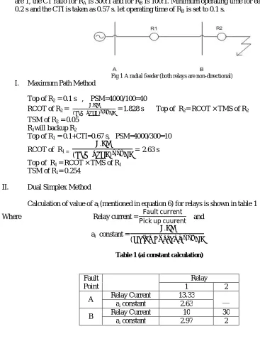
I-To test the algorithm, initially a simple radial system, shown in figure 1, is considered. The maximum fault current just beyond bus A and bus B are 4000 A and 3000 A respectively, the plug setting of both the relays are 1, the CT ratio for RA is 300:1 and for RB is 100:1. Minimum operating time for each relay is considered as
0.2 s and the CTI is taken as 0.57 s. let operating time of RB is set to 0.1 s.
Fig 1 A radial feeder (both relays are non-directional)
I. Maximum Path Method
Top of R2 = 0.1 s , PSM=4000/100=40
RCOT of R2 =
.
( ). = 1.828 s Top of R2= RCOT × TMS of R2
TSM of R2 = 0.05
R1will backup R2
Top of R1 = 0.1+CTI=0.67 s, PSM=4000/300=10
RCOT of R1 =
.
( ) . = 2.63 s
Top of R1 = RCOT × TMS of R1
TSM of R1= 0.254
II. Dual Simplex Method
Calculation of value of ai (mentioned in equation 6) for relays is shown in table 1
Where Relay current =PickFaultupcurrentcuurent and
ai constant =
.
( ) .
Table 1 (ai constant calculation)
Considering X1 and X2 as TMS of Relay RA and RB5 respectively, the problem can be stated as :
Min Z = 2.63X1 (8)
subjected to 2.63 X1-2. X2≥ 0.57 (9)
2.97 X1≥ 0.2 (10)
Fault Point
Relay 1 2
A Relay Current 13.33 __ ai constant 2.63
2 X2≥ 0.2 (11)
.The optimum solution to this problem is obtained in three iterations. The iterations are shown in table 2, 3 and 4.
Table 2 Iteration 2 (slack variables are basic)
As, at the end of third iteration, all the values in the Cj- ΣCi aij row are non positive, the optimal solution reached.
From above table
X1(TMS of R1)=0.2592 and X2(TMS of R2)=0.1
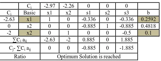
III. Proposed Method
L.P Model : We can get a Matrix from the equation (6) foe finding the TMS of the relay show below,
Cj -2.63 -2. 0 0 0
Ci Basic x1 x2 s1 s2 s3 b
0 s1 -2.97 2 1 0 0 -0.57
0 s2 -2.63 0 0 1 0 -0.02
0 s3 0 -2 0 0 1 -0.2
∑Ci aij 0 0 0 0 0
Cj- ∑Ci aij -2.63 -2 0 0 0
Ratio 0.8855
Table 3 Iteration 3 (s1 comes out x1 enters)
Cj -2.63 -2 0 0 0
Cj Basic x1 x2 s1 s2 s3 b
-2.63 x1 1 -0.3367 -0.336 0 0 0.1919
0 s2 0 -1.771 -0.885 1 0 0.3047
0 s3 0 -2 0 0 1 -0.2
∑Ci aij -2.97 1.771 0.885 0 0
Cj- ∑Ci aij 0 -3.771 -0.885 0 0
Ratio 1.8855
Table 4 Iteration 4 (s3 comes out x2 enters)
Cj -2.97 -2.26 0 0 0
Ci Basic x1 x2 s1 s2 s3 b
-2.63 x1 1 0 -0.336 0 -0.336 0.2592
0 s2 0 0 -0.885 1 -0.885 0.4818
-2 x2 0 1 0 0 -0.5 0.1
∑Ci aij -2.63 -2 0.885 0 1.885
Cj- ∑Ci aij 0 0 -0.885 0 -1.885
From solving the above matrix,
X1(TMS of R1)=0.259 X2(TMS of R2)=0.1
From section [I] , [II] and [III] we can compare the results in table 5 shown below,
Table 5 comparison results
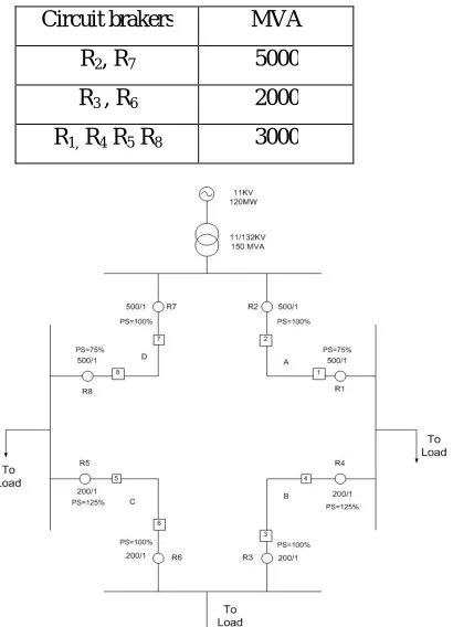
B. Illustration II-
A ring main feeder system is shown in figure 2. It allows supply to be maintained to all the loads in spite of fault on any section. Relays 7 and 2 are non directional whereas all other relays (1, 3, 4, 5, 6, and 8) are directional OC relays. All directional relays have their tripping direction away from the concerned bus. Operating time is 0.2 s taken .CTI is 0.25 s taken .TMS of R1 and R8 is 0.1 taken. Shown in figure 2 and the breaking capacity of the
circuit breakers are given in table 6 below,
Table 6 Breaking Capacity Of Circuit Breakers
Fig 2 4-Bus ring main system Maximum
Path Method
Dual simplex Method
New Method L.P
R1 0.254 0.259 0.259
R2 0.05 0.1 0.1
Circuit brakers MVA
R2, R7 5000
R3 , R6 2000
The calculation of relay current and ai constant for the system shown in figure 2 is shown in table 7 below,
Table 7 current seen by the relays and i a constant for relays are
From table 7 and methods explained in illustration I, the Result Comparison between maximum path method, dual simplex method and proposed method for system shown in figure 2 shown in table 8 below,
Table 8 Comparison results all three method for ring system
Relay TMS
Maximum Path Method Dual simplex Method New Method L.P
R1 0.1 0.1 0.1
R2 0.5 0.08 0.08
R3 0.25 0.32 0.3
R4 0.35 0.43 0.41
R5 0.35 0.43 0.41
R6 0.25 0.32 0.3
R7 0.5 0.08 0.08
R8 0.1 0.1 0.1
V. CONCLUSION
The new proposed method in this paper is superior to previous technique and provides flexibility due to the possibility to incorporate different network configurations and fast convergence due to smaller matrix dimension. In the coordination, higher speeds could be achieved for the relays employed .Other capabilities are different relay characteristics L.P.
REFERENCES
[1] Hossein Askarian Abyaneh, Majid Al-Dabbagh, Hossein Kazemi Karegar, Seyed Hesameddin Hossein Sadeghi, and Rana Abul Jabbar Khan, “A New Optimal Approach for Coordination of overcurrent Relays in interconnected Power Systems”, IEEE Transactions On Power Delivery, vol.18, No.2, APRIL 2003.
[2] Paithankar Y. G., and Bhide S. R., “Fundamentals of Power System Protection”, Prentice Hall of India Private Limited, New Delhi, 2007. [3] Badri Ram, and Vishwakarma D. N., “Power System Protection and Switchgear”, Tata McGraw Hill Publishing Company Limited, New Delhi,
2008.
Fault Point
Relay
1 2 3 4 5 6 7 8
A
Relay
Current 8.74 6.5 16.4 - - - - - ai
constant 3.15 3.67 2.43 - - - - -
B
Relay
Current - - 21.86 17.49 17.49 - - - ai
constant - - 2.3 2.3 2.3 - - -
C
Relay
Current - - - - 39.36 49.2 19.68 - ai
constant - - - - 2.3 2.3 2.28 -
D
Relay
Current 26.2 - - - - - 26.24 34.99 ai
[4] J. P. Whiting and D. Lidgate, “Computer prediction of IDMT relay settings and performance for interconnected power systems”, IEE Gen., Transmiss., Distrib., vol. 130, no. 3, pp. 139–147, 1983
[5] R. Ramswami and P. F. Mcguire, “Integrated coordination and short cir-cuit analysis for system protection”, IEEE Trans. Power Delivery, vol. 7, pp. 1112–1119, July 1992.
[6] P. E. Sutherland, “Protective device co-ordination in an industrial power system with multiple sources”, IEEE Trans. Ind. Applicat., vol. 33, pp. 1096–1103, July/Aug. 1997.
[7] Chattopadhyay B., Sachdev M.S., and Sidhu T.S., “An Online Relay Coordination algorithm for Adaptive Protection using LinearProgramming Technique”, IEEE Trans. on Power Delivery, vol 111, pp. 165-173, Jan 1996.
[8] Lemke C.E., “The dual method of solving the linear programming problem”, Naval research and logistics quarterly, vol. 1, no. 1, pp 36- 47, 1954.
[9] Rao S.S., “Engineering optimization – theory and practice, third edition”, New Age International (P) Limited, Publisher New Delhi, 1998. [10] Taha H., “Operations research – an introduction, eighth edition”, Dorling Kindersley (India) Pvt.Ltd., New Delhi, 2009.
[11] Bhavesh Bhalja , R . P . Maheshwari , Nilesh G. Chothani, “Protection and Switchgear”, Oxford University Press. [12] Pradeep Prabhakar Pai , “Operation Research Principles and Practice ”, Oxford UniversityPress.
[13] P. Bedekar, Sudhir R. Bhide ,Vijay S. Kale , “Optimum coordination of overcurrent relays in distribution system using dual simplex method”, Conference on Emerging Trends in Engineering and Technology, ICETET-09.
[14] S. S. Rao, Optimization (Theory and Application), 2nd ed. New Delhi.
[15] A. S. Braga and J. T. Saraiva, “Co-ordination of directional overcurrent relays in meshed networks using simplex method”, Proc. IEEE MELECON Conf., vol. 3, pp. 1535-1538,1996.
[16] A. J. Urdaneta, R. Nadira, and L. prez, “Optimal co-ordination of directional overcurrent relay in interconnected power systems”, IEEE Trans.Power Delivery, vol. 3, pp. 903–911, July 1988.
[17] Bhuvanesh A. Oza , Nirmal Kumar C Nair , Rashesh P Mehta , Vijay H Makwana, “Power System Protection and Swichgear” , Mcgraw